Introduction to A1015


Introduction to A1015
- A1015 is a part of transmissive light sensing sequence which has a high competence GaAs Infrared light discharging diode which actions as the light stemming component, extremely sensitive phototransistor is used as the light sensing element.
- It is commonly used PNP transistor for the intensification and switching submissions.
- It is a less signal user transistor it is used to amplify low signals it can also use as a switching device.
- Distinctive hFE standards for this small signal transistors series from 10 to 500, having extreme Ic evaluations from around 80 to 600mA.
- Its extreme working frequencies assortment is from 1 to 300 MHz.
- It is mainly used when intensifying small signals, such as an insufficient volt and only when using milli-amperes of current.
- For such apparatuses which devour a large quantity of current it is used for them instead of it, we use power transistors.
Pinout of A1015
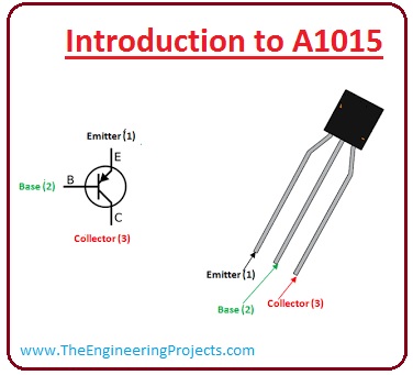
- These are the main pinout of A1015.
-
Lest see a diagram of the pinout.Pin# Type Parameters Pin#1 Emitter The emitter is for the external association of current. Pin#2 Base The base administers the biasing of the transistor. It vagaries the state of the transistor. Pin#3 Collector The collector is for the current inward drive. It is related to the load. 

Features of A1015
- These are some features of A1015.
- It is a transistor like PNP.
- It dispels the power of 0.4 watts.
- The supreme voltage at which it functions is 50 volts and current at its collector is 150mA.
- Its noise value is low approximately its value is 1dB.
- It is assembled in a readymade plastic coating.
- Its direct current gain value is 400.
- The power it consumes at the collector is 400 milliwatt.
- The value of itemization voltage at (C-E) and (C-B) is 50 volts DC.
- The value of permeation Voltage at BE is 1.45 volts of DC.
- Its matching transistor is 2SC1815
- Its Operational Temperature and Stowage Temperature is -55? to +150?.
Working of A1015
- Now we discuss working of A1015 by a circuit diagram which is described below.
- The circuit which is we are using in this tutorial is a LED flasher which has A1015, capacitor which mention in the given diagram as C1 and resistor R1 both of these are working as a frequency generator for Q1 transistor this transistor works as a switch for Q2 transistor.
- As C1 and R2 work as a switch for Q1, it will works till the voltage discharge upsurges crosswise of C1. As a consequence, Q2 flinches working, and a current drifts through LED and it goes ON.
- Although C1 settled over R1 to a period of time when C1 emancipation out there would be no compression to bias the base point of the Q1.
- Henceforth, the Q1 stop operation which also halts Q2 to operate. Consequently, LED turn OFF and C1 will switch again and this rotation lasts. And, the spiraling ON and OFF of LED appears as a flasher.

Applications of A1015
- These are some applications of A1015.
- It works as a switch in different projects.
- It uses in driver phase amplifier accomplishment.
- It used as an audio frequency amplifier.
- It can also use a Darlington pair.
- It used in the creation of led flasher.
×
![]()