


What is Norton's Theorem


What is Norton's Theorem
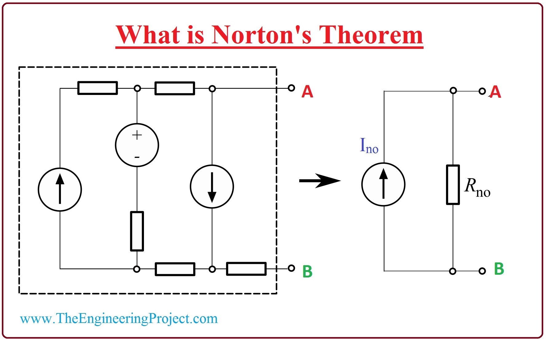
- Norton Theorem says that any circuitry which has many power supplies and resistors can be swapped with the circuit which has current source and one resistor in its parallel.
- This theorem is appropriate to both AC and DC circuitries. It works in AC circuits for impedance and resistance calculations. But in the case of DC circuits, it works for resistance measurements.
- In the given figure, there is a circuitry at which Norton theorem is applied.
- It is linear circuitry which has current (I) and voltage (V) sources and single resistor, this circuit is swapped with the resultant circuitry which has a current source (Ino) with the parallel resistor (R).
- The current (Ino) is the current which is measured at the points (A-B) of the circuitry.
- The resistor (R) in the circuitry measured at the points (A-B) by short-circuited the voltage supply and open-circuited the current supply.
Steps for Norton Theorem
Step 1: To apply the Norton theorem first eliminate the load resistor of the circuitry. Step 2: Measure the interior resistance of the source system by turn off the supplies in the circuitry. Step 3: After this connect the points of the output and measure the short-circuit current. Step 4: The resultant circuitry of Norton can be made by putting interior resistor in parallel with the short-circuit current. Step 5: At the end add resistance which we removed during the first step then find the load current.Norton Equivalent Circuit to DC Circuit Conversion
- Let’s we have a given circuitry at which we have to apply Norton Theorem. In this circuit, our load or output resistance is the R2 which is two ohms.

- For this, first of all, we will eliminate the output resistor (R2) from the circuitry and connect the points a and b.
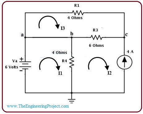
- The direction of current moving in the circuitry is shown in the diagram.
- You can see from the circuitry there are three loops and three currents are moving in the loops. Now we will apply KVL on these loops and find currents.
- If we apply KVL on the first loop then we have this resultant equation.


V- (I1 – I2)R4 = 0
[6 – (I1 – I2)R4] = 0
- As we know the value of (I2) which is (-4A) by putting this value in the above equation we have.
[6- (I1 – (-4))] =0
- Solving this equation we have.
I2 = -2.5 amperes
- Now we apply KVL at loop three, its crossponding equation is.
(I3)(R1) – (I3 –I2)(R3) = 0
(-4)(I3)- (6)(I3 +4) = 0
(-10)(I3) =24
I3 = -2.4 amperes
So, (In) = (I1 –I3)
= (-2.5 + 2.4)
= 0.1 amperes
- It is the current which is moving from A to B.
- Now we calculate the equivalent resistor which (RN). For this resistor, you should swap all supplies in the circuitry with their interior resistors.
- The value of the net resistance at the points a and b is
RN = (10 x 4)/ (10+4)
= 2.85?
- Now we add the current source (IN) with the resistor (Rn) to make Norton circuitry which is shown in the diagram.
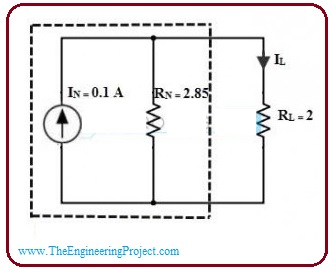
- To measure the output variable, we now add the load resistor at the load points.
- The load current IL will be.

IL = (IN) × [RN / (RL + RN)]
= (0.1) x [ (2.85)/(2+2.85)]
= 0.05 amperes
- For the variable value of the resistor, the current is given here.
When (RL) = (8 ohm)
IL = (0.1) × [(2.85) / (8 + 2.85)]
0.02 Amperes
Working of Norton Theorem
- As we have discussed different steps to apply the Norton theorem. Now we apply these steps practically on a given circuit.
- In the specified figure, we construct a circuit which has three resistances and two voltage sources.

- To apply the Norton theorem, first of all, remove the centered forty-ohm resistor and join the terminals A and B then we get circuit shown in the figure, represented by A.
- When we join two points A and B, then 2 resistances become parallel to each other then we can find the current passing through this 2 resistance.

I1=10v/10ohm = 1A,
I2 =20v/20ohm =1A
- The value of the short current is the sum of these two currents.
I (Short-Circuit) =I1 + I2= 2A
- Now if we remove the voltage sources from the circuit and connect open points with each other and also open the connection among the point A and point B.
- Now the 2 resistances are efficiently linked with each other in parallel.
- The values of interior resistance (Rs) can be found by the sum of resistance at point A and B, the circuitry for this procedure is shown in the figure and represented by B.
RT =(R1 x R2)/(R1+R2) =6.67 ohm
- After finding the value of the equivalent resistor (Rs) and short circuit current (Is), we make a Norton corresponding circuit. Which is represented in the picture by C.
- Now we have made Norton equivalent circuit, but we have to resolve circuit for the forty-ohm resistance which is connected across the point A and point B. this circuitry is signified in the figure by D.
- We can see in diagram (D) that the two resistors (Rs) and (RL) are now connected in parallel so we find the values of total resistance Rt.
Rt= (R1 x R2)/(R1+R2) = 5.72 ohm
- The value of the voltage at point A and B with load resistance is found by the formula.
VA-B = I x R =2 x 5.72=11.44V
- The value of current across load resistance is;
I= V/R=11.44/ 40 =0.29A

Limitations of Norton’s Theorem
- This formula is appropriate for the linear modules like resistors.
- It’s not for such modules which are not linear like diodes, the transistor.
- It also not operate for such circuitries which has magnetic locking.
- It also not work for such circuitries which has loaded in parallel with dependent supplies.
×
![]()


