AMS1117 LDO Regulator Pinout, Datasheet, Features


Introduction to AMS1117
- The AMS1117 is a common voltage regulator mainly used for high-efficiency linear regulation and post-regulation switching supplies.
- This 3-pin device is also used as a battery charger and comes with an output voltage range from 1.5V to 5V. It returns a low dropout voltage of 1.3A when it operates at maximum current.
- The AMS1117 series of voltage regulators comes with both fixed and adjustable voltages and are constructed to support up to 1A current. The dropout voltage is 1.3V which decreases at low load currents.
- The current limit is applied to the power source circuitry and regulator to compensate the stress when this regulator comes across the overload situations.
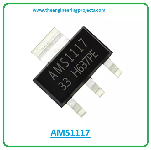
- AMS1117 is available in three packages i.e. surface mount SOT-223 package, TO-252 (DPAK) plastic package, and 8L SOIC package.
- Moreover, this device is compatible with three-terminal regulators like SCSI and is widely used in battery-powered instrumentation.
- This regulator is also used in some cases to obtain a negative voltage.
AMS Datasheet
Before installing this device into your project, it’s wise to go through the datasheet of the component that gives an overview of the main characteristics and power ratings of the device.AMS1117 Pinout
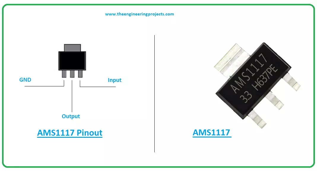
The following image shows the pinout diagram of AMS1117.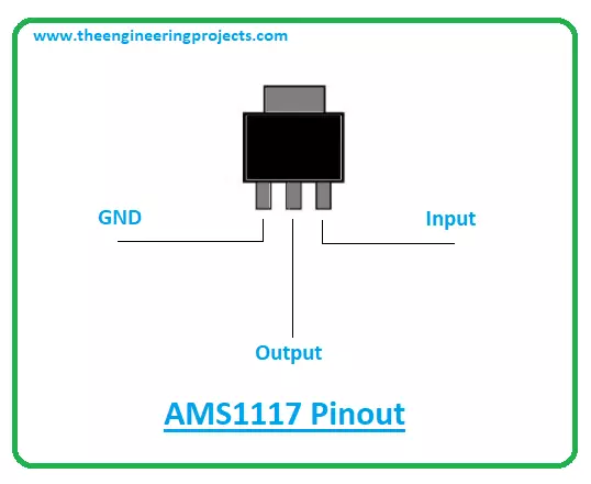
AMS1117 Features
The following are the features of AMS1117.- Low Drop-Out (LDO) Voltage regulator
- 3- terminal Fixed/Adjustable Linear voltage regulator
- Fixed Voltage type: 1.5V, 1.8V, 2.5V, 2.85V, 3.3V and 5V
- Adjustable Voltage range: 1.25V to 13.8V
- Built-in thermal and current limiting protection.
- Output current = 1000mA
- Operating junction temperature = 125°C
- Maximum Drop-out Voltage = 1.3V
- Available in three packages: SOT-223, SO-8 Package and TO-252
AMS1117 Usage
- Used in Arduino boards to regulate 5V and 3.3V, AMS1117 is similar to other linear voltage regulators like LM317, 7805. It is commonly famous for small form factor and is available in SMD package.
- They all, however, are configured for a maximum current of 1A. It is widely applied in active SCSI terminators and power management for a notebook.
- Depending on the output voltage and package, this linear voltage regulator is categorized into many types.
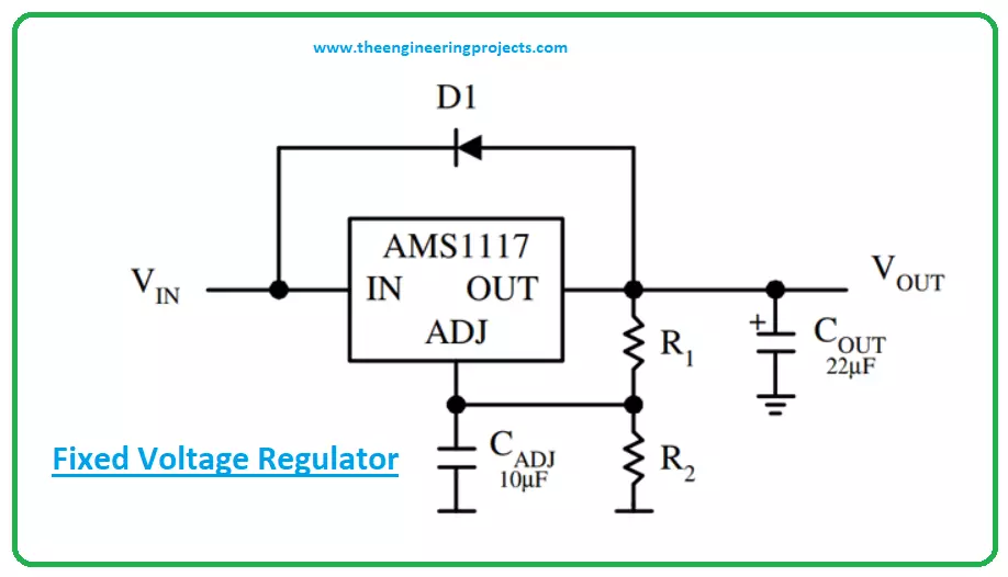
- If a fixed voltage is applied at the Vin pin of the regulator we’ll get a regulated output voltage at the Vout pin. The Adj/Ground pin is grounded in this case.
- We need to add a capacitor at the regulated output voltage to remove any noise from the regulator. The circuit diagram of the fixed voltage regulator is given below.
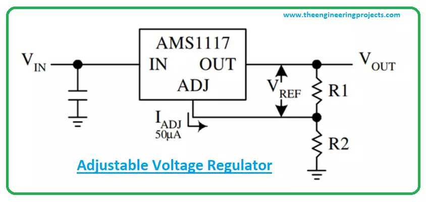
- In an adjustable type voltage regulator, two external resistors are included to identify the regulator’s output voltage.
- You can see from the circuit diagram below, two resistors R1 and R2 are added to identify the regulator’s output voltage.
- The capacitors are added to remove any noise from the circuit.
Vout = Vref * (1 + R2/R1) + Iadj * R2
For an Adjustable type voltage regulator we need two external resistors to decide the output voltage of the Regulator.- A reference circuit diagram for adjustable voltage is shown below, where the resistors R1 and R2 decides the output voltage of the regulator.
- The capacitor CAdj is an optional component that can be added to improve ripple rejection if required. The other two capacitors are to filter the input and output noise respectively.
LMS1117 Applications
- Used in current limiting circuits
- Employed in motor control circuits
- Incorporated in reverse polarity circuits
- Employed in variable power supply
- Used for voltage regulations
- Employed in Desktop PC systems
×
![]()