Up Down Counter without Microcontroller


Here, in this project, we are going to make an Up-Down counter. A simple counter counts in increasing or decreasing order but the Up-Down counter counts in increasing and decreasing order, both depending upon the input it has given.
But I am having an interesting question about the counter. Let suppose if the counter is counting in increasing order then up to which value, it will count because it can not count to infinite which means it has to reset after some certain value, and I believe that you must be having the same doubt as well. Basically every counter resets itself after a certain value and that value depends upon the bits of a counter.
Let suppose, we have a 8 bit counter which means it will count a maximum of up to 255 after which, it will reset to 0. So the size of the counter depends upon the bits of the counter.
So, in this project, we are going to make a counter which will count from 0 to 9 after which it will again reset to 0.
Software to install
We will make this project in the simulation first, for that we will use a simulation software which is Proteus.
Proteus is a simulation software for electronics based circuits. In this software we can make different types of electronic circuits and we can run the simulation and can monitor the working of that project in real-time only.
And it is a good practice also while making any new project. First of all, we should make a simulation of that project so that we can debug any issues without damaging any real components.
Proteus has a very huge database of all types of electronics components pre-installed.
Components Required
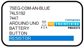
In this project, we will use the following components:
- 7 Segment LED display
- Push buttons
- Resistors
- 74LS192 (BCD/DECADE UP/DOWN COUNTER)
- 7447 BCD to 7-Segment Decoders/Drivers
Components details
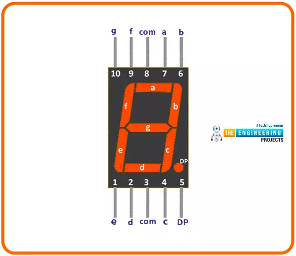
7 Segment Led display
- It is an LED display module in which there are seven LEDs arranged in the rectangular form on which we can display single digit numbers from 0-9 and some alphabets as well.
- It has two types, one is common ground and another is common Vcc.
- There are 7 different pins for each LEDs and one common pin, this pin can be common ground or common Vcc depending upon type of the display.
- The pins on the display are noted as a,b,c,d,e,f, and `g.
- Common ground is also known as Common cathode, and common Vcc is also known as Common anode .
- In Common cathode type display, the LEDs will glow when LEDs pins are connected to logic HIGH.
- In Common anode type display, the LEDs will glow when the LEDs pins are connected to logic LOW.
- As they are simple LED’s so while using them in the circuit, it is mandatory to use some protection resistors with each of them if we are using Common ground type display and single resistor with the Common Vcc pin if we are using the Common Vcc type display.
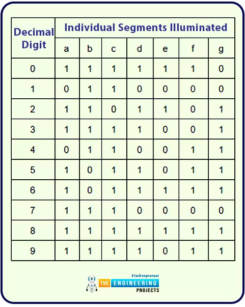
- For the counter, we will follow the truth table of display for showing the numbers.
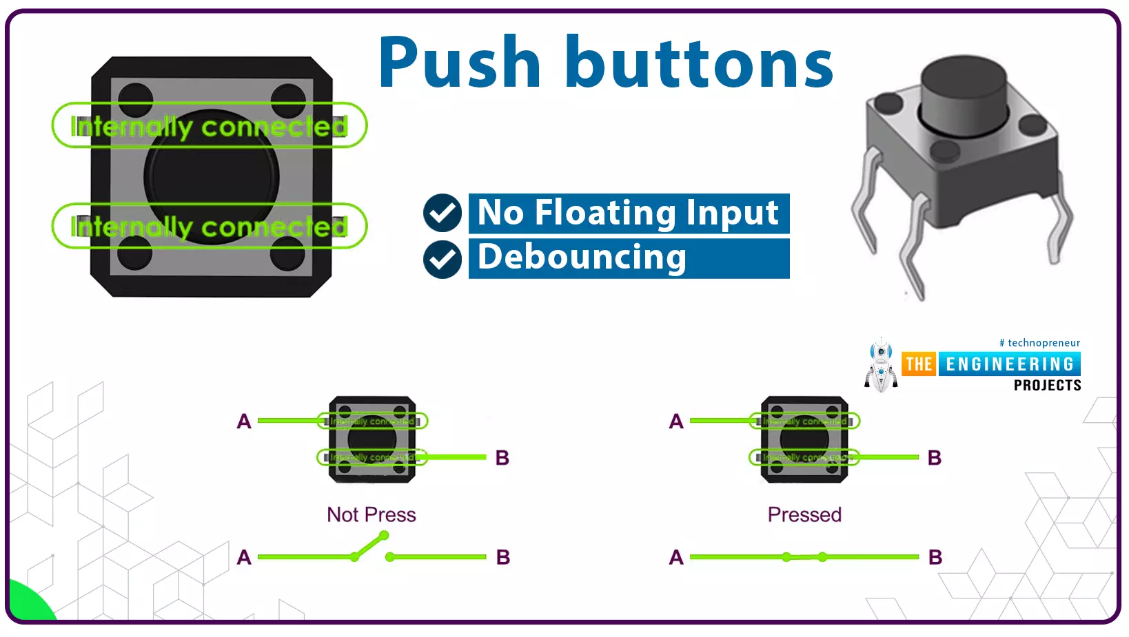
Push buttons
- Here, we have used a simple momentary push button for setting the counter in UP counting or in DOWN counting.
- There are two pins in the push button.
- As we will use the push buttons in active low condition which means one side will be connected to ground and other terminal will be connected to the Arduino.
- So when we press the push button, it will close the circuit and set the pin.
- While using any push button, it is mandatory to use a pull-up or pull-down resistor with it, otherwise there will be some glitches in the operation.
- Because when the button is released, the circuit will be opened and if there is no pull-up or pull-down connected to the other pin of the push button, then that pin will be in floating state and it will give any random voltage, which will create an issue.
- In this project, we have used the pull-up resistor so that when the push button is released, the pin state will be in logic HIGH state.
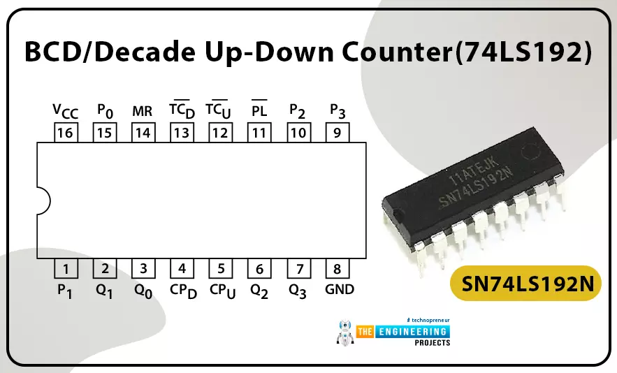
BCD/Decade Up-Down counter (74LS192)
- 74LS192 is an Up/Down BCD decade counter IC. It is developed by Motorola.
- This is the main IC which is used in this project for counting purposes.
- It is one the simplest IC for Up/Down counters. It has two different input pins for selecting the Up counter or Down counter mode.
- It is a 16 pin TTL based IC. Operating voltage of the IC is 5v.
- And as per the data sheet for selecting the mode of counter there are basically four pins used and those are MR, PL, CPU, CpD.
- For counting, the MR pin should be logic LOW and the PL pin should be in logic HIGH.
- To start the counting in increasing order or upward, the down counter input pin(CpD) should be at logic HIGH state and the up-counter input pin (CpU) should send a pulse from logic LOW to logic HIGH after this sequence the IC will count upwards.
- We have to follow the same sequence for counting in decreasing order or downward, the up counter input should be at logic HIGH state and the down counter input pin (CpD) should send a pulse from logic LOW to logic HIGH after this sequence the IC will count downwards.
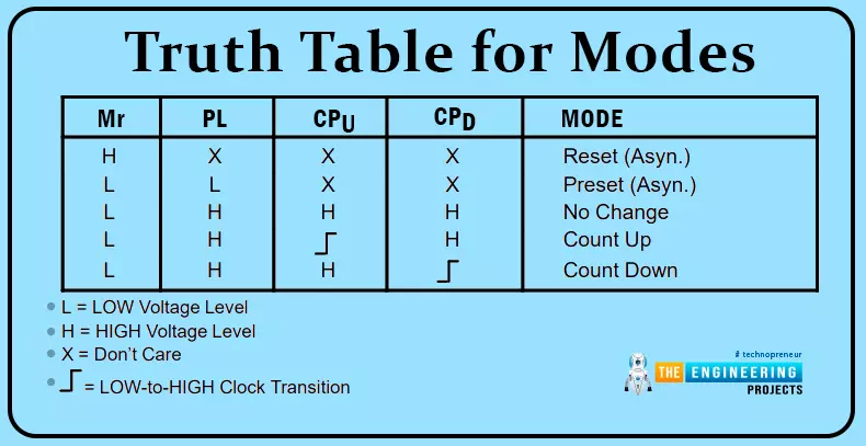
Truth Table for Modes
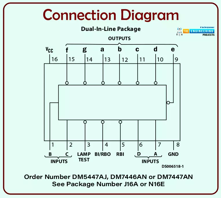
7447 BCD to 7-Segment Decoders/Drivers
- This IC is used in this project for controlling the 7-segment LED display.
- This is an active low output IC which means we can use its common anode LED display only.
- It basically converts the BCD number to decimal numbers on the 7-segment LED display.
- It has 4 input pins for reading the BCD input and depending upon which it will set the output pins for the 7 segment display.
- To set input pins depending upon the required output we will follow its truth table.
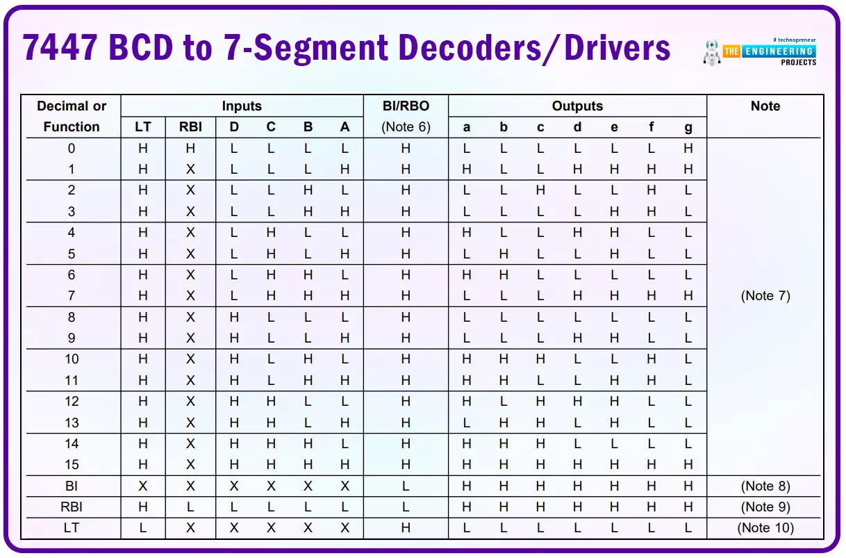
- To read more about this IC, follow the datasheet. BCD to 7-Segment Decoders/Drivers
Project overview
In this project, we will use two push buttons for controlling the counter as an Up counter or Down counter. The outputs from the push buttons will work as input for the BCD/DECADE UP/DOWN COUNTER IC. When we press the push button, there will be a change in the signal pin of the IC and according to the truth table when the signal changes from logic HIGH to LOW and the other input clock pin is at HIGH state then it will change the output count value depending upon the selected pin.
Which means if we push the Up counter push button, it will send a pulse to CpU pin of the IC, afterwards it will process as the increment in the output value, so it will increase the current output value by one. Similarly, for the Down counter push button, when we press the button, it will send a pulse to the CpD pin of the IC, thereafter it will process as the decrement in the output value so it will decrease the current output value by one.
And the outputs of the BCD/DECADE UP/DOWN COUNTER IC will work as the input for the BCD to 7-Segment Decoder. And the output pins of the BCD to 7-Segment Decoder will be connected to the 7 segment LED with some protection resistor to prevent them from damaging.
The 7-Segment Led display will glow the LEDs depending upon the output values on the BCD to 7-Segment Decoder/Driver.
Now we know the workflow of our counter.
So let‘s move to the circuit of the counter.
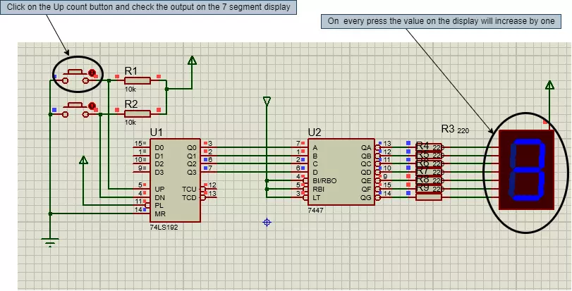
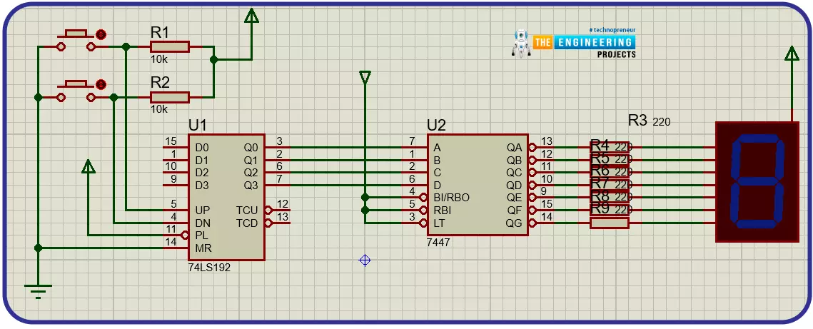
Circuit diagram and working
For making the project, we will be using the Proteus simulation software.
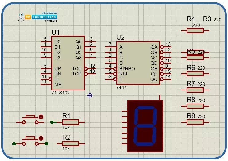
- First, start the new project in the Proteus and import all the required components into the workplace.
- After importing all the components in the workplace, let’s start connecting those.
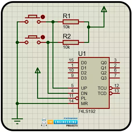
- First of all, we will connect the push button with the BCD counter IC.
- As we know, the push button has to be connected in pull mode so we will connect a resistor with each of the push buttons and another terminal with the BCD counter IC.
- Another terminal of the Up counter push button will be connected to the ‘UP’ pin of the BCD counter IC and the Down counter push-button terminal will be connected to the ‘DN’ pin of the counter IC and other pins like MR will be connected to the Vcc and PL pin will be connected to the ground.
- All the connections are made as per the datasheet of the IC.
- After this, we will connect the output pins of the BCD counter to the input pins of 7 segment LED driver IC. While connecting the pins of the IC, make sure they are connected in the correct sequence otherwise it will not display the correct value on the LED display.
- Now we will connect the protection resistors and the 7-segment LED display with the output of the 7 segment LED driver IC.
- After connecting them our circuit will be ready.
- Before testing it, do not forget to re-verify the connections.
Result and test
Now we have our circuit ready, it is time to test it.
- Start the simulation by clicking on the play button in the Porteus simulation.
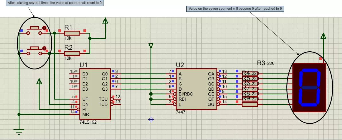
- First we will check for the Up counter.
- Press the Up counter push button. When we press the Up counter push button then the value on the 7 segment display will increase and if we continuously press it then the counter will go up to 9, afterwards it will reset to 0.
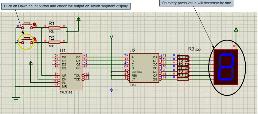
- Now check the Down counter. Press the Down counter push button, then the value on the 7 segment display will decrease and if we continuously press it then it will reach to 0 and thereafter it will start from the 9 again and will be decreased to 0.
Conclusion
I hope we have covered all the aspects of this project. And I think it will be a very useful learning project as well. Now if we see any scoreboard, immediately we will be knowing the electronics behind it. I hope you have enjoyed reading this project. Please let us know in the comment section if you have faced any issues while making this project.
Thanks for reading this article. See you in the next project.