Simple Home DIY Projects for Embedded Hobbyists


Hi Friends! Hope you’re well today. I’ll welcome you on board. In this post, I’ll walk you through How a Hobbyist Can Work on Electronic Projects in America.
From smartphones to security systems and appliances to advanced automation equipment, electronics seem to engulf every aspect of life. And with the recent advancement in technology, this trend will continue to make our lives easy and better for years on end. BUT… before you can take part in the development of innovative and advanced electronic machinery, you need to get your hands dirty with DIY electronic projects. These small and easy-to-handle projects give you confidence that you can do better and put your deliberate effort to delight the lives of people with your intellect.
If you’re just starting, we suggest you visit North America Hot Searched Electronic Platform which houses scores of electronic components that you can use in your electronic projects.
Curious to know more about how a hobbyist can work on electronic projects in America?
Keep reading.
How a Hobbyist Can Work On Electronic Projects In America?
Electronic devices are not cheap, however, there is a catch. Some small electronic devices and electrical projects you find online can be made in homes with a handful of tools and electrical components. There are some ready-made small kits and electrical modules like microcontrollers and Arduino boards that you can use in your electronic projects and develop a mini home-made electronic device.
In the following, I’m going to discuss some DIY projects that you can work on as a starter. No big setup. No advanced equipment is required. All you need to know is some basic computer skills and the right components to build something amazing from scratch.
1: Liquid Level Indicator
A liquid level indicator is a simple electronic project used to identify the current level of the liquid. It is widely used in a range of applications like irrigation control, fuel tank level, cooling tower, and level gauging in pumps.
Components Used
The following are some components used in this project.
3 PNP A1015 transistors
3 LEDs
9V battery
Breadboard
Battery Clips
Probes
Connecting Wires
PVC tubing
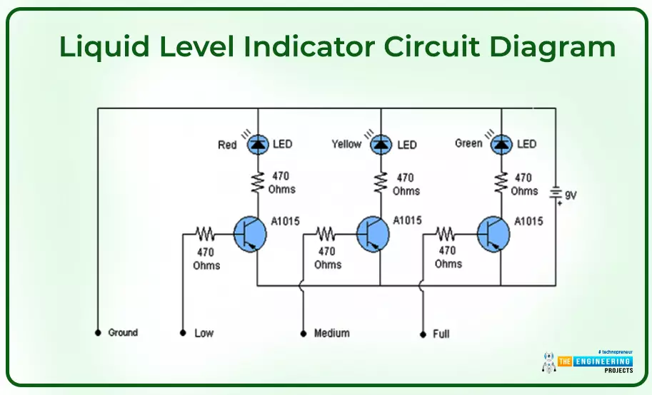
The following figure shows the circuit diagram of the project.
How it Works
The circuit shows the signal by lighting up the LED whenever a tank reaches a certain level. The tank is divided into 3 levels: Low, Medium, and Full, based on the liquid capacity of the tank. Similarly, three LEDs are included to indicate a certain level where Red LED shows the Low level, Yellow shows the Medium level and Green shows the Full level. The transistor base is connected with the copper or aluminum wire that acts as a probe.
Each transistor's base receives an electrical connection to 9V DC through water and the desired probe indicating the liquid level is started to rise. Consequently, this causes the transistors to conduct, causing LEDs to illuminate and show the level of liquid.
2: Beep Circuit
A beep circuit is a very handy electronic device mainly used for generating a quick sound in emergencies in places like fire brigade stations, police stations, hospitals, and factory areas for smoke detection. Devices like security and alarm systems use this circuit to send alert warnings of the emergency.
Components Used
1KΩ, 1.2KΩ, 470Ω Resisters
NPN 2N4401 Transistors
LED
9V Battery
2-input NAND Gate
Connecting Wires
Breadboard
Battery Clips
The following figure shows the circuit diagram of the Beep Circuit.

How It Works
The output at the pin4 IC continuously goes up and down based on the 2 NAND gates that are wired as a-stable multi-vibrator. This setup switches the 2N4401 transistor ON & OFF which serves as a driving force for the piezoelectric buzzer. In turn, the buzzer produces a beep sound triggering the LED continuously.
3: LED Flash Light
This is a simple and cheap circuit. LEDs are widely used to produce durable light with low power. This circuit consists of two AAA cells that are connected in series producing 3V in total. It is enough to generate high-power illumination with an input current of just 20mA.
Components Used
2 AAA cells (1.5V each)
Push button
LED
Connecting Wires
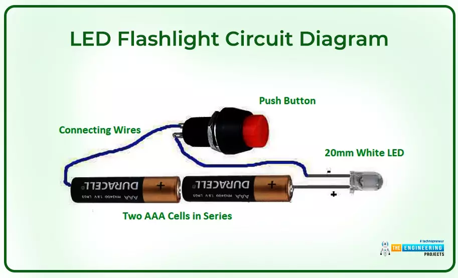
The following figure shows the diagram of the LED Flash Light Circuit.
How it Works
In this figure, the LED is connected with the positive and negative terminals of the 3V battery using two cells. A push button is connected in series between the battery and the LED. When you push the button, it will instantly complete the circuit, allowing the charge to pass through LED and, in turn, illuminating it.
4: Metal Detector Circuit
Metal detector circuits, as the name suggests, are used to detect the existence of any metal. These devices identify the change of magnetic field which is directly related to the distance of metal objects. They are used for a range of purposes like security screening and detecting the traces of metals in food products.
Components Used
PVC Tubing
NPN BC548 Transistor
LM7806 Voltage Regulator
10uF/16V Electrolyt ic Capacitor
100pF, 10pF Ceramic Capacitor
Resistors
6V Battery
Breadboard
Connecting Wires
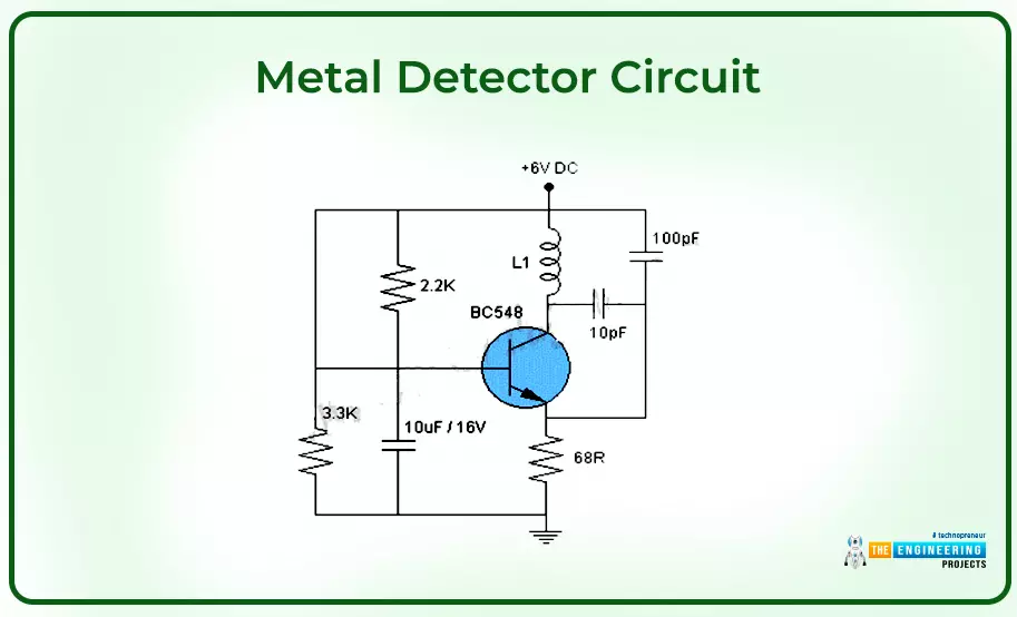
The following figure shows the circuit diagram of the metal detector circuit.
How It Works
The circuit is made of old radio and a single BC548 transistor. The AM radio produces a hissing sound when you place this circuit in the vicinity of any metal object, indicating the presence of metal within a range. The L1 indicates 60 turns of enameled copper wire that is wired on a 1cm PVC tube. The 6V battery is used to power up the circuit.
5: Fire Alarm Circuit
Fire alarm electrical device is commonly used in factories to detect the presence of fire. When a fire breaks out in a place, the circuit instantly identifies the smoke produced by the fire, triggering an alarm sound to warn people about it within range.
Components Used
The following components are used in this circuit.
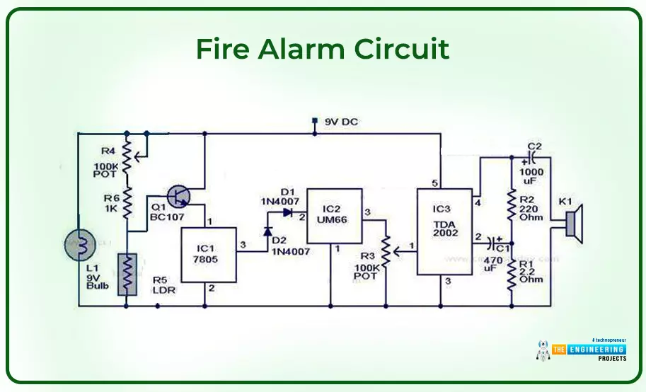
The device is equipped with LDR to detect smoke
IC UM 66 acts as a tone generator
IC 7805 used to run a tone generator
TDA 2003 IC is an alarm system that acts as an amplifier to give signals to the speakers
9V battery that serves as a power source
Resistors
Capacitors
Breadboard
Connecting Wires
The following figure shows the circuit diagram of the fire alarm circuit.
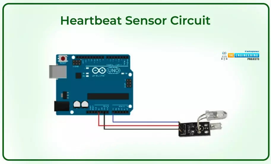
6: Heartbeat Sensor With Arduino
Sensing the heartbeat is crucial for patients and athletes to identify the current condition of the heart. This way they can do preventive maintenance of the heart to ward off potential diseases. These sensors can be used in chest strips, smartphones, and wristwatches to monitor the heart rate.
Components Used
Arduino Uno
16x2 LCDs
Push Button
Connecting Wires
10KΩ Potentiometer
Heartbeat Sensor Module with Probe
Breadboard
330Ω Resistor
Working Principle
A method that measures changes in blood volume in an organ is called photoplethysmography . This method tracks variations in the brightness of the light entering the organ. The Heartbeat Sensor operates based on this idea.
An IR LED is commonly used as the light source in the sensor. LDR, photodiode, and photoresistor can be used as photodetectors.
The light source and photodetector can be arranged in two ways:
Reflective Sensor: In this setting, the detector and light source are next to one another. To read the heartbeat rate, the patient holds their finger in front of the sensor.
Transmissive Sensor: In this arrangement, the patient’s finger is placed between the receiver and transmitter, where the detector and source light face each other.
The following figure shows the diagram of the heartbeat sensor.
7: Wireless Doorbell
Wireless doorbell is commonly used in shops, hospitals, factories, offices, and garages.
This doorbell uses an RF module and hence comes with a wide range compared to wired or Wi-Fi doorbells.
Components Used
434 MHz RF Transmitter Module
434 MHz RF Receiver Module
Arduino UNO
750 KΩ Resistor
HT – 12D Decoder IC
HT – 12E Encoder IC
Push button
9V Power Supply
Buzzer
Breadboard
Connecting Wires
How It Works
The circuit comes with Arduino Uno and an RF module. The Arduino Uno is mainly used to analyze the data. The RF module is applied for the development of wireless communication.
A wireless doorbell system can be powered by batteries or by connecting to the home's main electrical supply. Wireless doorbell installation is simple since no wiring is required. For the receiver, only a power outlet will do.
The following figure shows the circuit diagram of the wireless doorbell.

8: Hand Wash Timer
We are all aware of how coronavirus rattled the entire world. Apart from wearing masks outside, washing hands was crucial to prevent the wrath of the virus. Since when you don’t wash your hands and touch your face or food, the virus is likely to spread to people around you. This is where the handwash timer comes in handy.
Components Used
Ultrasonic Sensor HC-SR04
Three LEDs: Red, Blue, Green
Breadboard
Connecting Wires
Working Principle
It is a simple electronic project where Arduino is the brain of the countdown timer. We’ll attach the Arduino with 6 LEDs and an ultrasonic distance sensor.
With the help of the distance sensor, the Arduino transmits ultrasonic sound waves and measures the amount of time it takes for the sound waves to be reflected back to the sensor. It calculates the distance to whatever appears in front of it using the current time. In turn, the Arduino continuously reads the sensor while witnessing your hand come within 20 centimeters.
The Arduino turns on the red LED and waits for you to wash your hands with water and soap for four seconds as soon as it senses movement within 20 centimeters. The 20-second countdown then begins. The five blue LEDs eventually begin to illuminate one by one over 20 seconds.
Turning up the green LED will indicate that you have washed your hands for a considerable amount of time, at which point you can rinse the soap off.
The following figure shows the circuit diagram of the handwash timer.

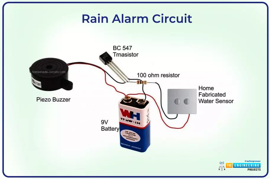
9: Rain Alarm
Rain Alarm is a nifty electronic project to detect the presence of rain. It will turn on the buzzer when its sensors detect rainwater.
Components Used
BC 547 Transistor
100 Ohm Resistor
Home Fabricated Water Sensor
9V Battery
Piezo Buzzer
Breadboard
Connecting Wires
The following figure shows the Rain Alarm Circuit Diagram.
How It Works
Raindrops that bridge over the screw tips make up the sensing element. When the drops fall on the screw tips, it allows a tiny electrical current to pass through the metal and turn on the transistor's base. The transistor then begins to conduct and increases the conductivity across its collector/emitter terminals.
In turn, the connected buzzer gets turned ON, giving the signals to the concerned authority to take appropriate action to deal with the rainwater.
Key Considerations While Working on the Projects
Hope you have got enough information about some simple and easy-to-handle electronic projects to give you hands-on experience in dealing with electrical circuits and components. But there are some key considerations that you need to follow that will help you to successfully take your project from start to finish to execution.
Make sure the contact between the soldering iron and the component doesn’t last longer than 1 sec. Otherwise, it will hurt the efficiency of the component, or worse, can completely damage the product.
Always pay special heed to the positive and negative terminals of the components while making connections.
Install the main ICs and modules like microcontrollers at the center of the whole circuit. This will help to evenly manage the connections with the relevant electrical components.
Make a tight connection between the circuit and the components. Loose connection makes affect the working of the final project.
Read the manuals that come with ICs or electronic modules. This will help you have a better understanding of the product and what you can do to avoid damage.
That’s all for today. Hope you’ve enjoyed reading this article. If you’re unsure or have any queries, you can ask me in the section below. I’d love to help you the best way I can. Thank you for reading the article.