Automatic Garage Door with PLC Ladder Logic


Hello my friends! I hope your doing very good. Today we are going to practice what we have learnt through the ladder logic tutorial series. We bring a new .project which is mostly exist in our daily life that is electrical door control. in garage for domestic and public garage, you should found automatic garage gate or door that is controlled by the PLC ladder logic program. So today we are going to implement the project including determining the input and output components, design the logic, programming and testing using the simulator.
Project details
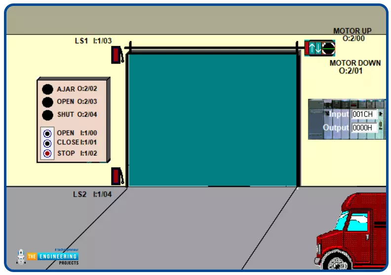
Figure 1 shows the project’s components, inputs and outputs that are included in controlling the garage door. As you can see my friends, there are inputs like open, close, and stop requested by push buttons. Also, you can see sensors like the two limit switches on the bottom and on the top to prevent overload that might have occurred on the motors. Moving to the outputs, there are motor up and down directions, open, close, and ajar status indicators lamps. So what is the next step in our plan to achieve such job? Of course we need to list these inputs and outputs and give them addresses. Then we design the logic based on the user requirements and the safe operation.
Inputs and Outputs list
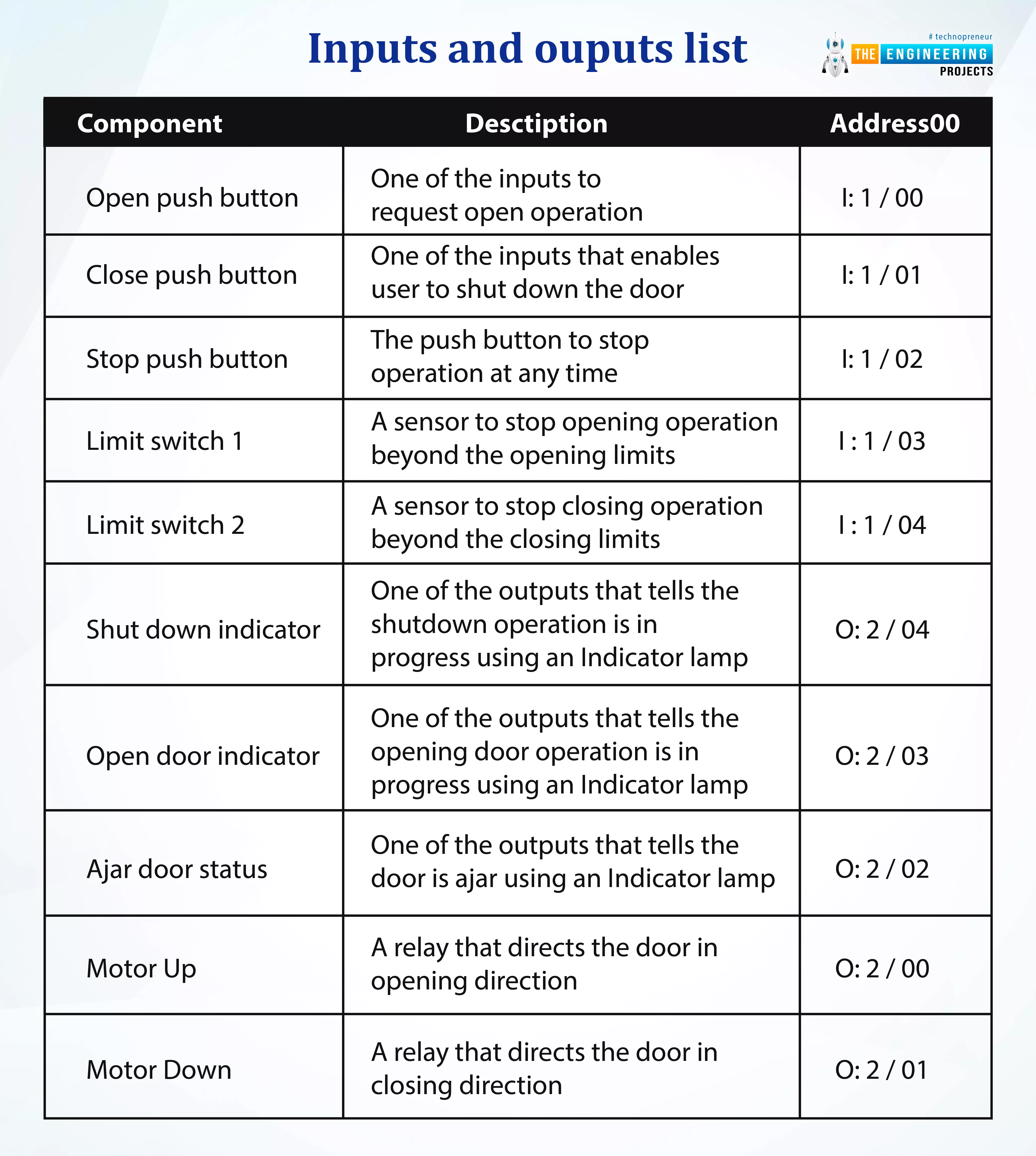
Table 1 lists the inputs and outputs showing the name in the first column, the description In the second column, while the addresses are listed in the last column.
Component |
Description |
Address00 |
Open push button |
One of the inputs to request open operation |
I: 1 / 00 |
Close push button |
One of the inputs that enables user to shut down the door |
I: 1 / 01 |
Stop push button |
The push button to stop operation at any time |
I: 1 / 02 |
Limit switch 1 |
A sensor to stop opening operation beyond the opening limits |
I : 1 / 03 |
Limit switch 2 |
A sensor to stop closing operation beyond the closing limits |
I : 1 / 04 |
Shut down indicator |
One of the outputs that tells the shutdown operation is in progress using an Indicator lamp |
O: 2 / 04 |
Open door indicator |
One of the outputs that tells the opening door operation is in progress using an Indicator lamp |
O: 2 / 03 |
Ajar door status |
One of the outputs that tells the door is ajar using an Indicator lamp |
O: 2 / 02 |
Motor Up |
A relay that directs the door in opening direction |
O: 2 / 00 |
Motor Down |
A relay that directs the door in closing direction |
O: 2 / 01 |
The logic operation
After receiving the requirements of the client that tell how the door will be operated, managed, and controlled, we need to add the restrictions and safety conditions that secure the equipment like the motor, supply, sensing components. So the following lines state the operation and restrictions that need to be followed to achieve the designated task as follows:
The door opening and or closing shall be stopped at any time user / operator hit stop push button
The door shall open by requesting opening operation using the designated push button
The door shall close by requesting shut down operation using the designated push button
The indicator lamp of opening operation shall be lit while opening operation is in progress
The indicator lamp of closing operation shall be lit while shut down operation is in progress
The ajar status lamp shall be lit at any time the door is not fully opened or totally closed
Restrictions:
The opening operation can not be requested while shut down process is in progress
The shut down operation can not be requested while opening operation is in progress
The opening operation can not proceed any further beyond the designated limit to avoid any overload on the motor
The shut down operation can not proceed any further beyond the designated limit to avoid any overload on the motor.
Ladder Logic Code for Garage Door Project
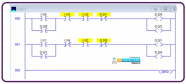
The ladder logic program of the project is shown by figure 2. It shows two rungs, one for opening process and second for the shut down operation. The program can be more lengthy but we professionally resumed it in only two main rungs. The first rung represents the door opening operation in which, open push button initiates the opening process and the latching is there to let the opening process continue till the limit switch LS1 contacted or the stop is requested by hitting the stop push button. In addition, security of the process has been considered by including the condition of not having a shutdown process in progress represented by O:2/1. On the other hand, the shut down process is represented by the second rung. The shut down process initiated by the shut down push button and latching the door closing relay for continuing the shut down process unless one of the restriction conditions is met. The restriction conditions of shut down are the limit switch LS2, the door opening in progress, or a stop has been requested by operator using the stop push button. Also, indicator of the process status are included to show the opening operation thanks to the door opening indicator and the shutdown indicator. But we missed the ajar status of the door so let us add one rung for that.
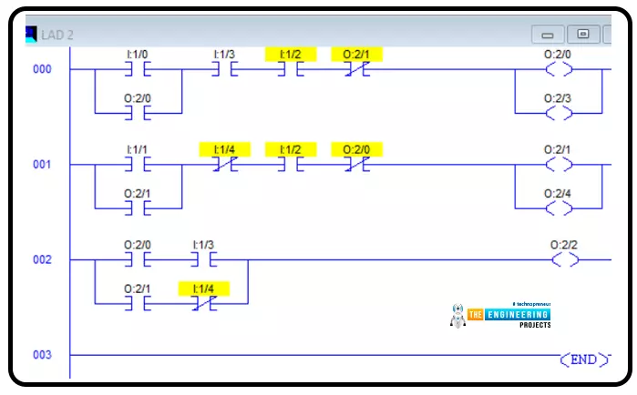
As you see guys, the third rung has been added to implement the ajar status. It is simply clear that when the opening is in progress without reaching to the fully open indicator, or the shut down process is in progress without reaching to the totally closed, the ajar lamp is energized. Now let us go testing what we have coded so far and see if it is correct or not. But first you guys should sit and list the test cases that you should try to make sure the system is going to perform correctly and safely as well.
Testing the project
Door Opening test
In this test , we hit the opening door push button to request opening the door. As you see my friends, the door is opening as in figure 3 and the opening indicator is lit. also you can see the ajar indicator is lighted because the door is not reached the final opening position.
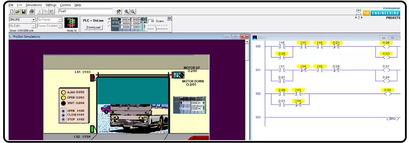
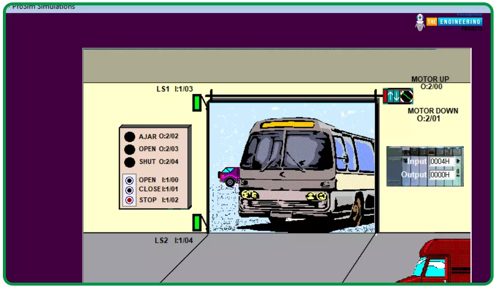
Figure 5 shows the state of the process after reaching the final position for opening the door. It is clear the process safely completed and the limit switch LS1 is gone green. Also the ajar status and opening indicators have been turned off.
Door closing test
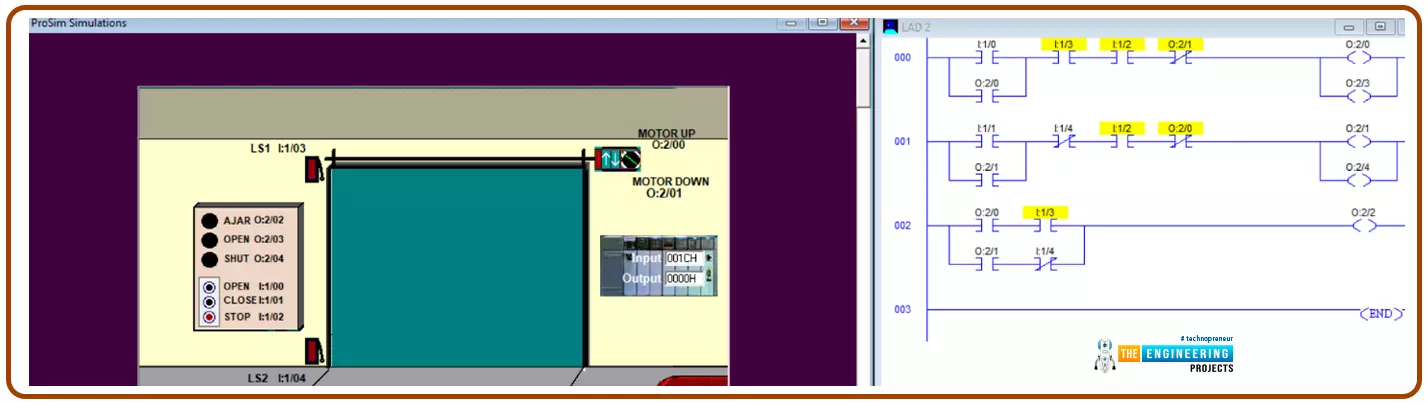
In this test , we hit the door shut down push button to request closing the door. As you see my friends, the door is closing as in figure 6 and the closing indicator is lit. also you can see the ajar indicator is lighted because the door has not reached the final shut down position.
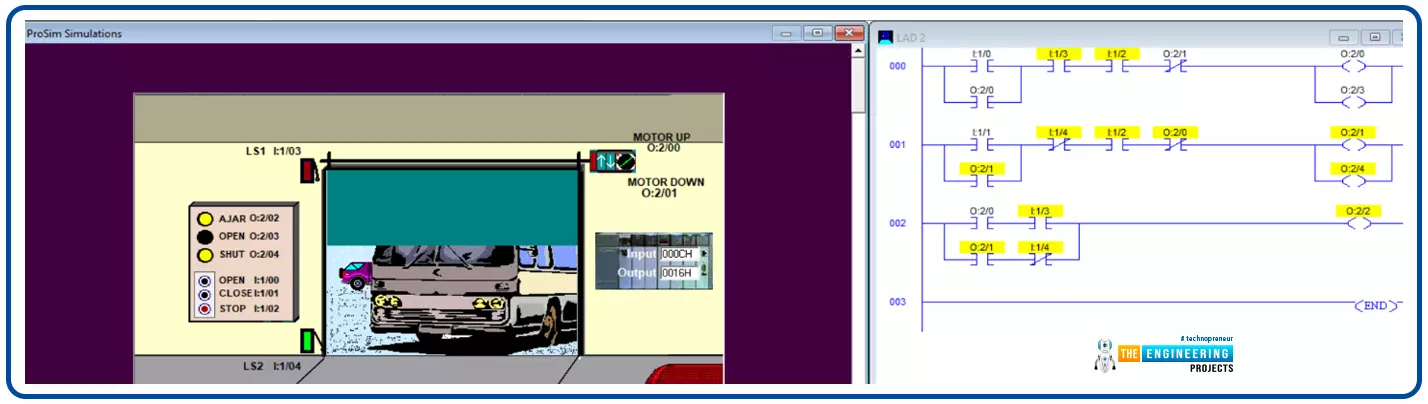
Figure 7 shows the state of the process after reaching to the final position for closing the door. It is clear the process safely completed and the limit switch LS2 is gone red. Also the ajar status and shut down indicators have been turned off.
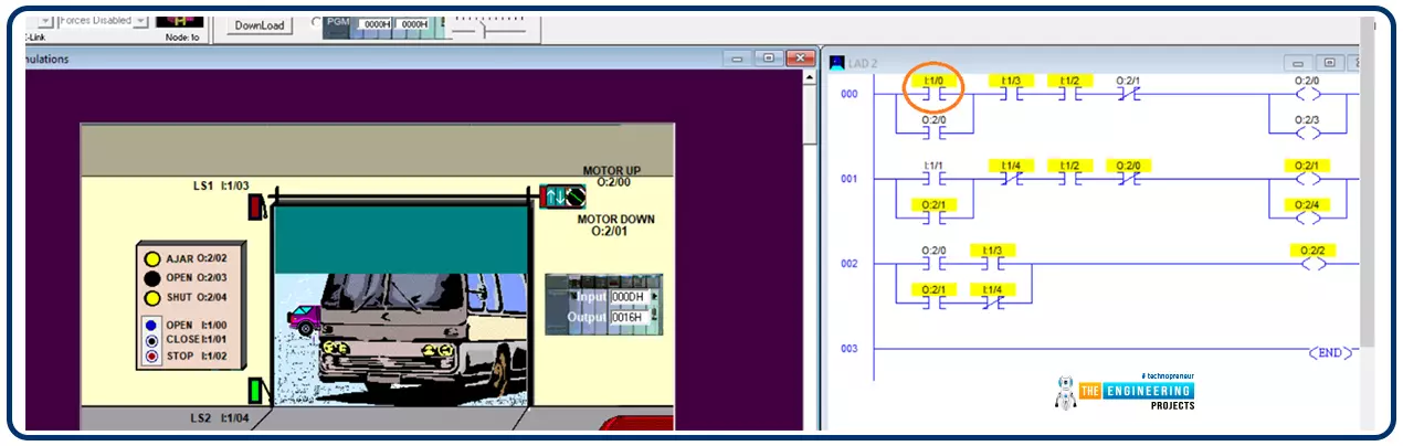
Security and Safety Test
In this test case we want to request opening .the door while it is shuting down and try to request shut down the door while it is opening to see is there any issue or not. Figure 8 shows what is going on when we requested opening the door while a shuting down process is inprogress. You can see guys in rung number one, the opening push button ,is pressed as circled and highlighted see I:1/0. However, the requested process has not performed due to the restriction that the shutdown process should not be in progress. Same thing when opening door is in progress, shut down requests are forbidden.