Hello friends, I hope you all are doing great. Today, I am going to share the new 28BYJ-48 Stepper Motor and ULN2003 Driver Library for Proteus V1.0. The little silver 28BYJ-48 with its blue cap and its green ULN2003 board is the first stepper motor most of us ever touch: it comes in nearly every Arduino starter kit, it costs very little and it runs from 5 V. Now it is ready for your Proteus simulations, with a dial on its output shaft so you can watch every step it takes, and every step it misses.
Behind the parts sit our own models. The ULN2003 board has its four Darlington outputs, the clamp diodes, the A B C D LEDs and the power jumper, and it reads the coil patterns your sketch writes: half step, full step, wave step or the wrong pin order that makes so many 28BYJ-48 motors buzz on the bench. The motor is a model too, with its four half-coils, its torque, the detent, the back-EMF and the real 63.68 : 1 gearbox, so it turns exactly as far as a real one, slows down, and loses steps when you load it too much. You get three devices: the ULN2003 board as a Simple device with a live STATUS panel and as an Advance device with a pop-up window and three test tools, plus the 28BYJ-48. The demo runs on our Arduino UNO V4.0 with both the Arduino Stepper library and AccelStepper.
NOTICE: a 28BYJ-48 is famous for two surprises: it never turns exactly once with 2048 steps, and with the wrong pin order it only hums. We wanted both to happen in Proteus just as on your desk, so the dial follows a rotor pulled by real coil currents through a real gear ratio. It took our team a lot of hard work. Your feedback is the fuel that keeps us going, so please tell us what you think in the comments below or in the Motor Driver board of our forum. And if our free libraries help you, you can buy us a coffee. So, let's get started with the 28BYJ-48 Stepper Motor and ULN2003 Driver Library for Proteus V1.0:
What is the 28BYJ-48 Stepper Motor?
The 28BYJ-48 is a small unipolar permanent-magnet stepper with a gearbox. Its name tells its size: 28 mm across. Inside the can are four half-coils that all meet at one common wire, the red one. Current in a half-coil, from the red wire to the orange, yellow, pink or blue wire, magnetizes the stator teeth, and the magnet rotor turns to line up with them. The orange (A) and pink (C) halves sit on one axis with opposite fields, and so do yellow (B) and blue (D).
The rotor makes 32 full steps per turn, but you never see the rotor: a four-stage plastic gearbox slows it down and gives the output shaft its torque. Most tutorials call the ratio 64 : 1, but the real gears are 32/9 x 22/11 x 26/9 x 31/10, which is 63.68395 : 1. So one turn of the shaft takes 2037.9 full steps or 4075.8 half steps, not 2048 or 4096. With "2048 steps per turn" the shaft goes 1.79 degrees too far every turn, which is why a 28BYJ-48 clock slowly runs ahead.
| 28BYJ-48 5V (the model) | |
|---|---|
| Type | unipolar permanent-magnet stepper with a 4-stage gearbox |
| Supply | 5 V (a 12 V version exists; this model is the 5 V motor) |
| Coils | four half-coils of 50 ohm and about 60 mH, common = red |
| Wires | orange A, yellow B, pink C, blue D, red common |
| Gear ratio | 63.68395 : 1 (32/9 x 22/11 x 26/9 x 31/10) |
| Steps per output turn | 2037.9 full steps, 4075.8 half steps |
| Holding at 5 V | about 82 mA per coil, about 55 mN.m on the output shaft (two coils on) |
| Speed | about 10 - 15 RPM; about 17 RPM with a ramp and no load |
| On the schematic | a dial on the shaft that turns at the real angle; RPM, angle, LOST and the LOAD button |
What is the ULN2003 Driver Board?
An Arduino pin can give about 20 mA, but a 28BYJ-48 coil takes about 80 mA, and a coil kicks back a voltage spike when its current stops. The ULN2003 solves both: it is an array of seven Darlington transistors, each one able to sink up to 500 mA, each with a clamp diode to a common pin. The green board uses four of them. A HIGH on IN1 switches output A on, which pulls the orange wire to ground, so current flows from the red common through the orange half-coil. A red LED on each output shows which coils are on.
| Board pin | What it does |
|---|---|
| IN1, IN2, IN3, IN4 | the inputs from the Arduino; HIGH = that output sinks current |
| A, B, C, D | the outputs to the motor's orange, yellow, pink and blue wires (the white connector) |
| + and - | the supply, 5 - 12 V (5 V for the 5 V motor), and ground |
| ON / OFF jumper | connects + to the motor's common (red); OFF = the motor gets no power |
| LEDs A B C D | light while their output is on |
| Devices in this library | ULN2003TEP (Simple), ULN2003ADVTEP (Advance), BYJ48TEP (the motor) |
Wave, Full and Half Step
The ULN2003 does no thinking of its own: it switches exactly the coils your sketch asks for. Walking the field around the motor in the right order is the job of the sketch. There are three ways to do it:
| Mode | Coils on | Sequence | Steps per output turn |
|---|---|---|---|
| Wave step | one at a time | A, B, C, D | 2037.9 (weakest torque) |
| Full step | two at a time | A+B, B+C, C+D, D+A | 2037.9 (the most torque) |
| Half step | one, then two | A, A+B, B, B+C, C, C+D, D, D+A | 4075.8 (finest, smoothest) |
Here is the trap. The coils sit in the order A, B, C, D around the motor, but on the board that means IN1, IN2, IN3, IN4, while the Arduino Stepper library and AccelStepper switch their four pins in a sequence made for a different coil order. That is why every working 28BYJ-48 sketch lists the pins as IN1, IN3, IN2, IN4, for example 8, 10, 9, 11. Give them in the natural order 8, 9, 10, 11 and the motor gets opposite coils together and 180 degree jumps: it only buzzes. Our demo has a command that shows exactly that.
What's New in 28BYJ-48 Stepper Motor and ULN2003 Driver Library for Proteus V1.0
- The real ULN2003 board: the green PCB with the ULN2003APG, the four LED resistors, the A B C D LEDs, the white motor connector, the input and power headers and the ON / OFF jumper, which you can click while the simulation runs.
- Darlington outputs with clamp diodes: each output drops about 0.75 V, and a coil current runs on through the diode when its output turns off.
- A 28BYJ-48 with a dial that turns at the simulated angle, through the real 63.68 : 1 gearbox, with RPM, angle, the steps LOST and a LOAD button that brakes it.
- Pattern analysis: the board tells half step, full step, wave step and the wrong pin order apart, and warns about opposite coils, 180 degree jumps and coils held too long.
- Three test tools on the Advance device: Sequence table, Pin order and Power.
- A two-node demo on our Arduino UNO V4.0: the Arduino Stepper library in full step on one node, AccelStepper in half step on the other, with serial commands and a WRONG command for the classic mistake.
- A compact package: about 1.30 MB, without the C++ source code of the model.
Three Devices: Simple, Advance and the Motor
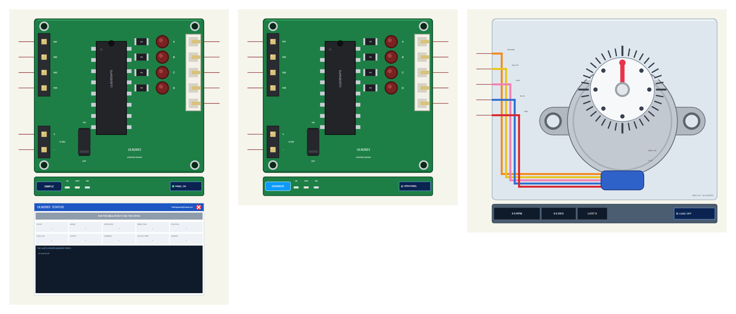
| Simple | Advance | Motor | |
|---|---|---|---|
| Device | ULN2003TEP | ULN2003ADVTEP | BYJ48TEP |
| On the schematic | The board + the STATUS panel | The board only | The motor with its dial |
| Status | Banner, 10 readouts, the last 6 events | A pop-up: Board, Event log, Tests | RPM, angle, LOST |
| Interaction | PANEL button, the jumper | OPEN PANEL button, the jumper | LOAD button, a click on the dial |
Download 28BYJ-48 Stepper Motor and ULN2003 Driver Library for Proteus
Click the button below to download 28BYJ-48-ULN2003-Stepper-Motor-Library-for-Proteus-v1.0.zip (about 1.30 MB, without the C++ source code of the model):
28BYJ-48 Stepper Motor and ULN2003 Driver Library for Proteus V1.0- README.txt: the devices, installation, the demo, wiring, the test tools and real hardware.
- Proteus Library Files:
TEPULN2003.LIBandArduinoV4TEP.LIBfrom our Arduino Library for Proteus V4.0. - Proteus Model Files:
TEPULN2003.DLLandTEPARDUINO.DLL. - Proteus Simulation:
28BYJ-48-ULN2003-Stepper-ArduinoUnoV4.pdsprj,BYJ48_Demo.hexand copies of the two DLLs. - Arduino Code:
BYJ48_Demo.inoand the AccelStepper library it uses (GPL-3.0, unmodified, with its licence). The Stepper library comes with the Arduino IDE.
No Proteus yet? Read How to Download and Install Proteus 7 and 8. New to libraries? Follow How to Install a New Library in Proteus.
How to Install 28BYJ-48 Stepper Motor and ULN2003 Driver Library for Proteus
- Close Proteus and extract the whole zip file, for example to your Desktop.
- Copy the two files from Proteus Library Files into the LIBRARY folder of Proteus (usually
C:\Program Files (x86)\Labcenter Electronics\Proteus 8 Professional\LIBRARY). - Copy
TEPULN2003.DLLandTEPARDUINO.DLLfrom Proteus Model Files into the MODELS folder. - Delete
TEPULN2003.IDXfrom the LIBRARY folder if it is there. - Start Proteus, press P and search for ULN2003 or 28BYJ.
Tip: keep the Proteus Simulation folder together, because the project needs its .hex file and the DLLs beside it. The library is tested in Proteus 8.5; Proteus 7 is not supported. For bigger steppers, see our A4988 / DRV8825 Stepper Motor Driver Library for Proteus with a NEMA 17; for DC motors, our L9110S and TB6612FNG libraries.
The ULN2003 Board in Proteus
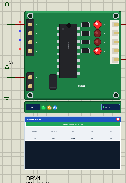
The board looks like the one in your kit, at about 1.6 times its size: the ULN2003APG chip, the four small resistors and the A B C D LEDs, the white five-pin motor socket, the IN1 to IN4 header, the + and - header and the jumper. The LEDs are live: each one lights while its output is on, so during a turn you see the pattern walk across them. Click the jumper during the simulation and the motor's common is cut, just as when you pull the real jumper.
Under the board is the TEP strip. The ON LED is green while the board has its supply, the STEP LED flashes with the steps and the DIR LED shows the direction. The strip, its LEDs and the panels are TEP additions; the real board has none of them.
The Simple device adds the STATUS panel. Its banner says what the board does, for example "RUNNING FULL STEP 341 STEPS/S CW", or shows HOLDING, RELEASED, WRONG PIN ORDER, NO SUPPLY, JUMPER OFF or the latest warning. Ten readouts follow: the state, the step mode, the step rate, the direction, the position, the coils on, the supply, the current, the RPM of the output shaft and the jumper. At the bottom are the last six events. The red X closes the panel, and the PANEL button on the strip opens it again.
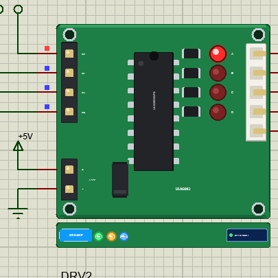
The Advance device keeps the schematic clean: only the board and its strip. Its live data opens in a pop-up window at Run, and the OPEN PANEL button brings the window back if you close it.
The 28BYJ-48 in Proteus
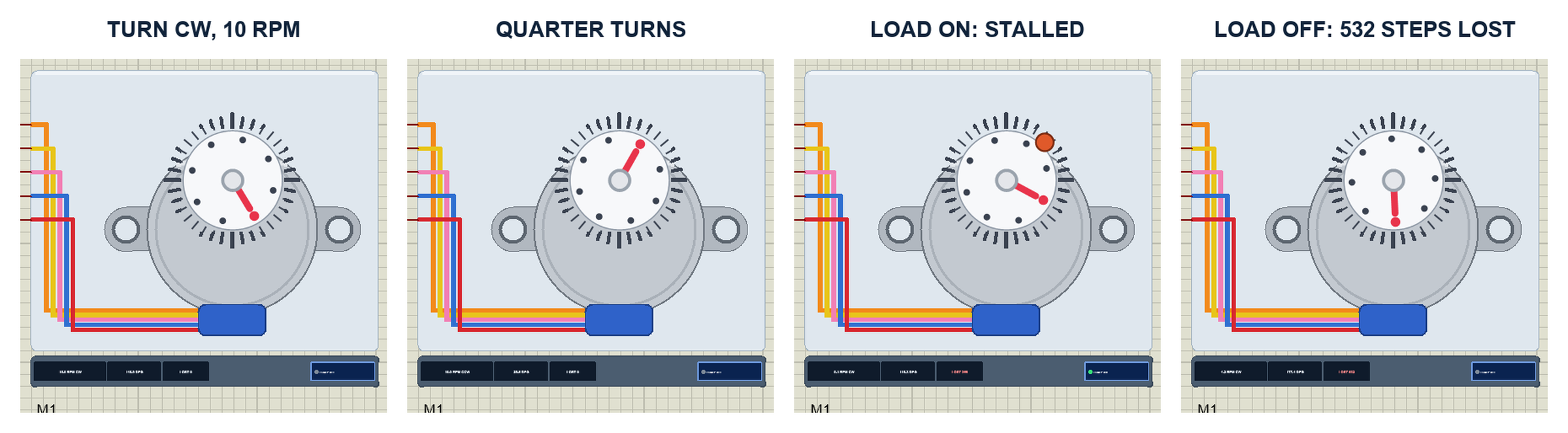
The motor is drawn from the front: the silver can with its two mounting ears, the blue cable outlet, a degree scale around the shaft and a white dial with a red pointer. The five wires leave on the left in their real colours. While the simulation runs, the dial turns at the real angle of the output shaft. The strip under it shows the RPM with its direction, the angle of the dial and LOST, the steps the rotor fell behind.
The dial is not a counter of steps. It follows the rotor of the model through the gearbox, and the rotor follows the magnetic field of the four coil currents. That is how the gear ratio shows: in the run, every "turn" of 2048 full steps from the Stepper library moved the dial 361.79 degrees, while AccelStepper's 4076 half steps per turn are only 0.02 degrees too many.
The LOAD Button and Lost Steps
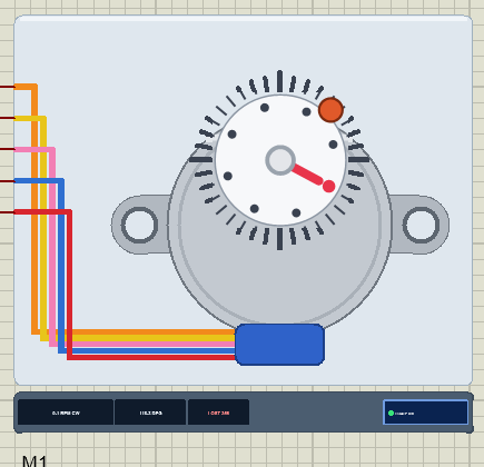
Click LOAD under the motor, or click its dial, and a brake presses on the shaft with 80 mN.m. The motor holds only about 55 mN.m at 5 V, so it cannot turn: the field moves on, the rotor stays, and every time the field gets a whole electrical turn ahead the rotor slips back by four full steps. The model counts those slips as LOST steps and writes them to the log, for example "M1 lost 168 full steps (172 in all) - the load is above the motor's torque". The property LOAD adds a constant load in mN.m for the whole run.
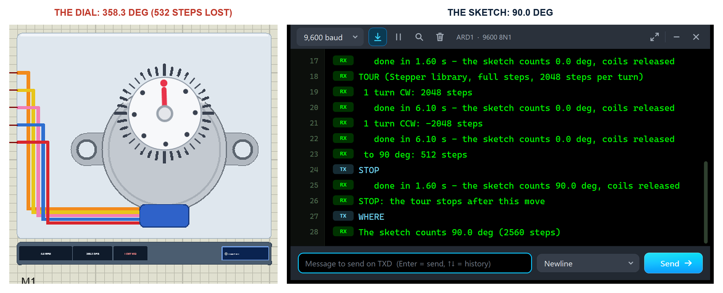
This is the most important lesson of any stepper. In the run, LOAD was pressed just before the quarter turn to 180 degrees and released in the middle of the turn to 270: 532 full steps lost in all. The sketch only counts the steps it sent, so after the next moves it reported 90.0 degrees (2560 steps), while the dial stood at 358.3 degrees. Check the numbers: 2560 minus 532 is 2028 full steps, and 2028 / 2037.9 x 360 is 358.25 degrees. A stepper runs open loop: if it slips, nothing tells the Arduino, unless you add a sensor or a home switch.
The Demo Circuit
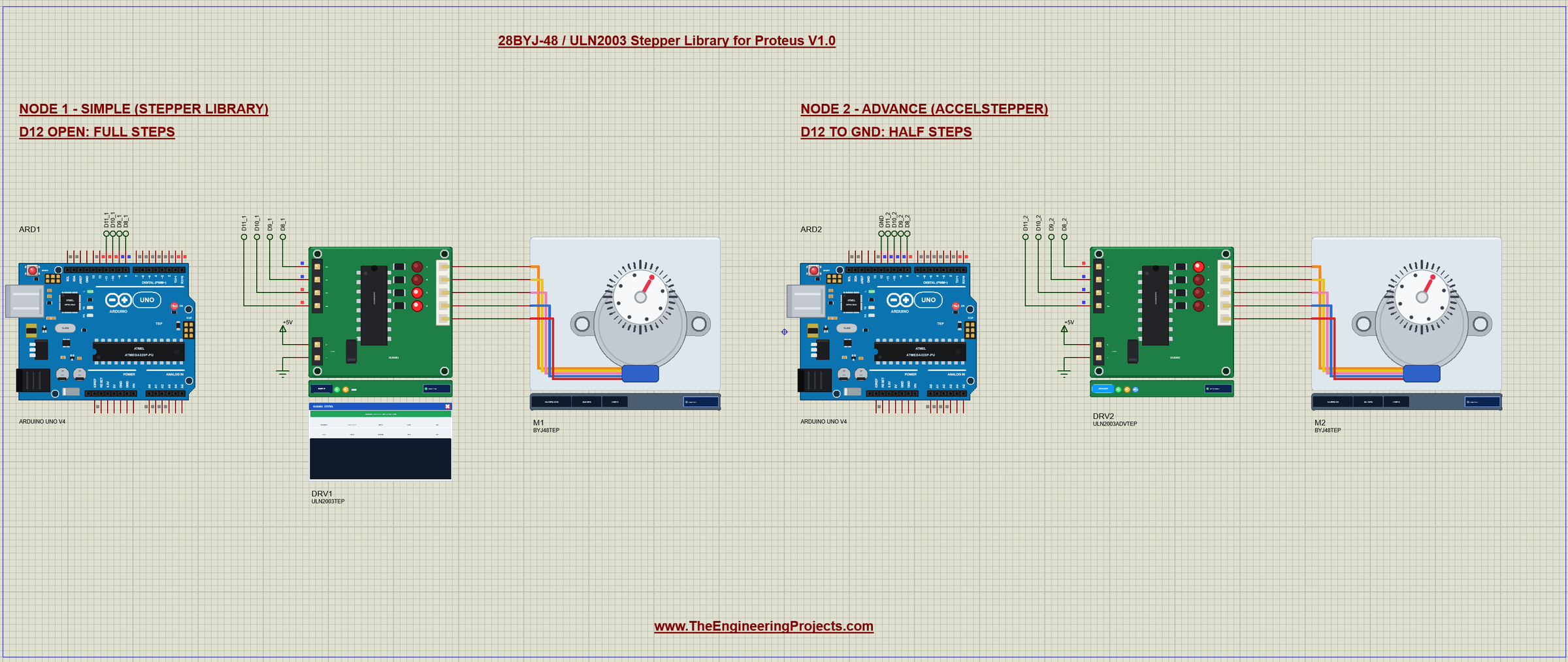
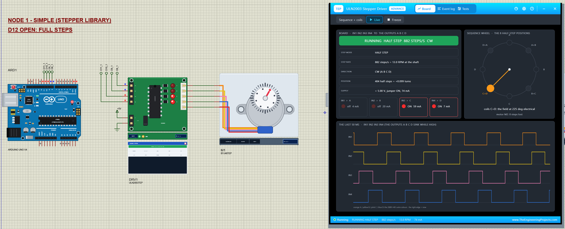
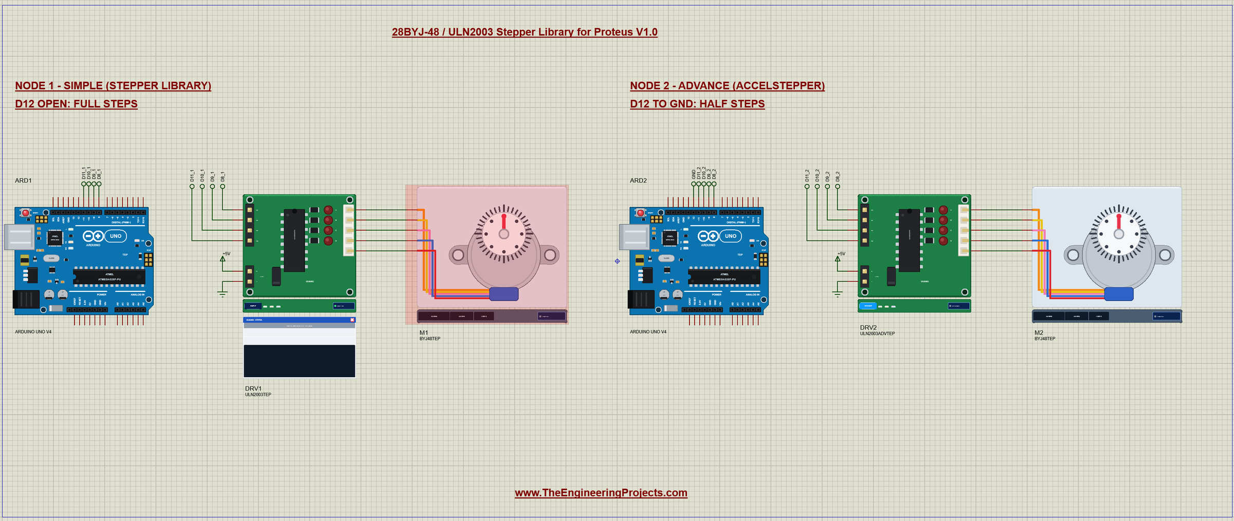
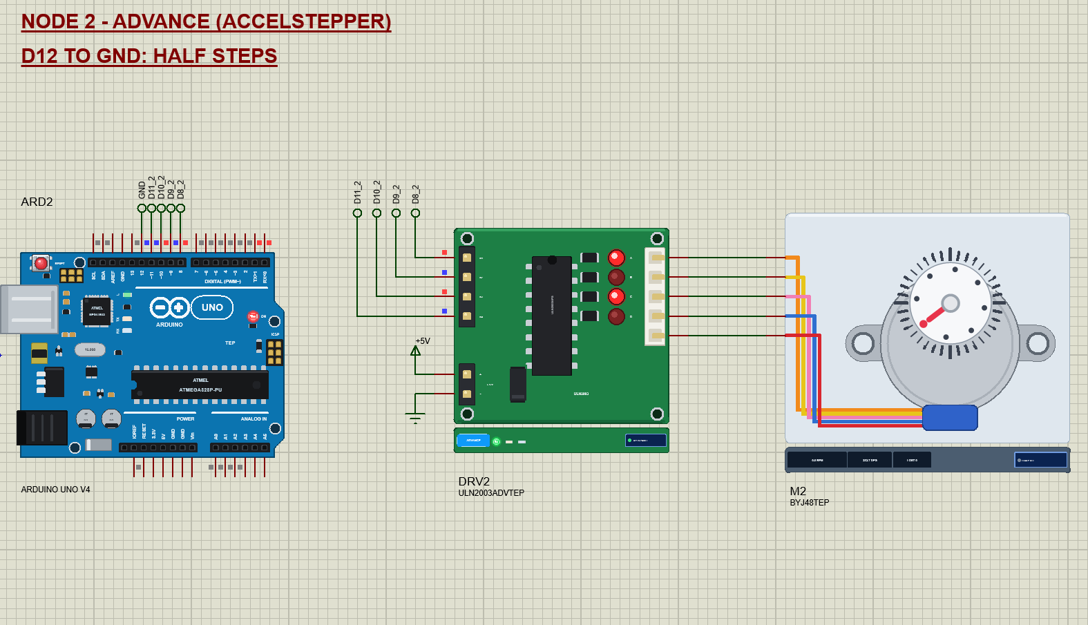
The demo project has two nodes. Each one is an Arduino UNO V4.0 from our Arduino UNO Library for Proteus V4.0, one ULN2003 board and one 28BYJ-48. Both UNOs run the same BYJ48_Demo.hex, and pin D12 chooses the library: node 1 leaves D12 open and uses the Arduino Stepper library in full step with the Simple board, node 2 ties D12 to GND and uses AccelStepper in half step with the Advance board. The + of both boards comes from a +5V power terminal, which Proteus turns into a 5 V supply.
Wiring
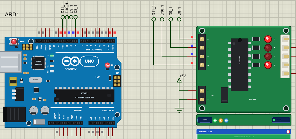
| ULN2003 board | Arduino UNO | Note |
|---|---|---|
| IN1 | D8 | output A, the orange wire |
| IN2 | D9 | output B, the yellow wire |
| IN3 | D10 | output C, the pink wire |
| IN4 | D11 | output D, the blue wire |
| + | 5V | the motor supply (better a separate 5 V supply on a real board) |
| - | GND | common with the Arduino |
| motor socket | 28BYJ-48 plug | orange A, yellow B, pink C, blue D, red common |
In Proteus every input reaches its UNO through a wire with a net label: D8_1, D9_1, D10_1 and D11_1 for node 1 and the same with _2 for node 2. ARD2's D12 has a GND label, which selects AccelStepper. The board's outputs sit in the same rows as the motor's wires, so they run straight across. The serial monitor needs no wires at all, because it is built into the UNO V4.0.
Node 1: the Stepper Library in Full Step
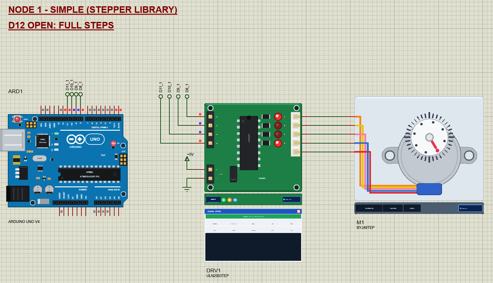
Node 1 uses the Stepper library that comes with the Arduino IDE, the way most tutorials do: 2048 steps per turn at 10 RPM, two coils on at a time. The tour turns the shaft once clockwise, once back, then four quarter turns of 512 steps with a short stop between them, and starts again. After every move the sketch holds the last step for 100 ms and then switches all four outputs off, so the motor does not warm up while it waits. The Stepper library has no ramp: it starts at full speed. On a PC we checked that the motor starts cleanly at 10 and 12.5 RPM but loses steps if it starts at 15 RPM.
Node 2: AccelStepper in Half Step
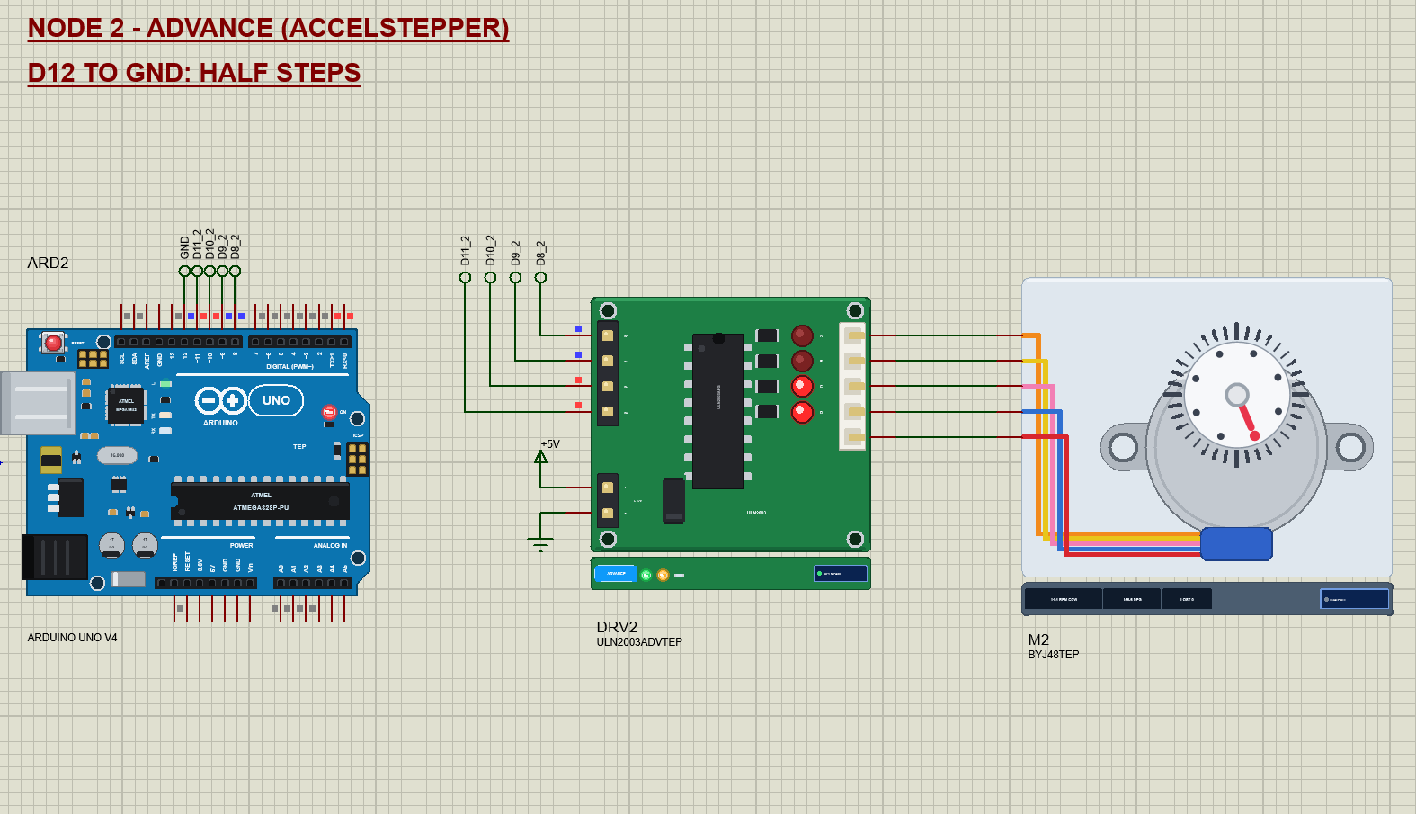
Node 2 runs the same tour with AccelStepper in half step: 4076 half steps per turn, which is much closer to the real 4075.8, accelerating to 1000 half steps per second (14.7 RPM at the shaft) in one second and slowing down at the end. The quarter turns are 1019 half steps and end on 90, 180, 270 and 360 degrees.
The Arduino Code
The demo uses two libraries: the Arduino Stepper library, which comes with the Arduino IDE, and the popular AccelStepper library by Mike McCauley, which adds acceleration and half steps. AccelStepper is in the zip under Arduino Code, or in the Library Manager of the Arduino IDE. New to Arduino? Start with Arduino Tutorial for Beginners and Introduction to Arduino UNO. The pins and the three stepper objects come first:
const uint8_t IN1 = 8, IN2 = 9, IN3 = 10, IN4 = 11, MODE_PIN = 12;
const int STEPS_PER_TURN = 2048;             // what the Stepper library examples use (the real gearbox: 2037.9)
const long HALF_PER_TURN = 4076;             // half steps per turn for AccelStepper (the real gearbox: 4075.8)

Stepper stepper(STEPS_PER_TURN, IN1, IN3, IN2, IN4);                 // full steps, the coils in the order A B C D
AccelStepper accel(AccelStepper::HALF4WIRE, IN1, IN3, IN2, IN4);      // half steps, the same order
Stepper wrongOrder(STEPS_PER_TURN, IN1, IN2, IN3, IN4);              // the classic mistake, for the WRONG command
Look at the pin order: IN1, IN3, IN2, IN4 for both libraries. AccelStepper::HALF4WIRE is the half step mode for four wires. The third object, wrongOrder, uses the natural order on purpose, for the WRONG command. In setup() the sketch reads D12 to choose the library:
  pinMode(MODE_PIN, INPUT_PULLUP);
  useAccel = digitalRead(MODE_PIN) == LOW;
accel.setMaxSpeed(1000); // half steps/s: 14.7 RPM at the shaft
accel.setAcceleration(1000); // full speed in 1 sA move works differently in the two libraries. The Stepper library's step() blocks until the move is done; AccelStepper only sets a target, and accel.run() in the loop makes the steps:
void startMove(long n) {
  moveSteps = n;
  moveStart = millis();
  if (useAccel) {
    moving = true;
    accel.enableOutputs();
    moveFrom = accel.currentPosition();       // never reset the position: in HALF4WIRE it picks the coil pattern
    accel.move(n);
  } else {
    stepper.step(n);
    moveDone();
  }
}
Note the comment about the position. In HALF4WIRE mode AccelStepper picks the coil pattern from its position, so if you reset the position with setCurrentPosition(0) between moves, the next move starts on a different pattern and the rotor jumps. We found that in the simulation: the dial lost steps until the sketch stopped resetting the position. The loop calls accel.run() and notices the end of a move:
  if (useAccel) {
    accel.run();
    if (moving && !accel.isRunning()) { moveSteps = accel.currentPosition() - moveFrom; moveDone(); pauseUntil = millis() + 500; }
  }
When a move ends, the sketch adds its steps to the angle it believes, holds the last step for 100 ms and releases the coils:
void moveDone() {
  moving = false;
  count += moveSteps;
  delay(100);                                // hold the last step until the rotor settles - released at once it coasts on
void release() { // all four outputs off: no holding torque, no current
digitalWrite(IN1, LOW); digitalWrite(IN2, LOW); digitalWrite(IN3, LOW); digitalWrite(IN4, LOW);
}Why the 100 ms? A light rotor that is released at the very moment of its last step still moves, and it can coast past the next detent. The simulation showed exactly that: without the pause, the motor lost four steps at the end of a turn. One more AccelStepper detail: stop() decelerates a running motor, but it does nothing to a move that has not made its first step yet, so STOP cancels such a move itself:
if (useAccel && moving) { accel.stop(); if (accel.speed() == 0) accel.moveTo(accel.currentPosition()); }The HEX file is in the package. To change the sketch, install AccelStepper, open the sketch in the Arduino IDE and export the compiled binary, as in How to get the HEX file from Arduino. It needs 13,882 bytes of flash and 572 bytes of RAM.
The Advance Pop-Up Window
At Run, the Advance device opens TEP ULN2003 Stepper Driver Advance, with the look of our TEP Serial Monitor Advance for Proteus. It has three tabs, Board, Event log and Tests, plus Settings and Help behind the gear and question mark icons.
The Board Page
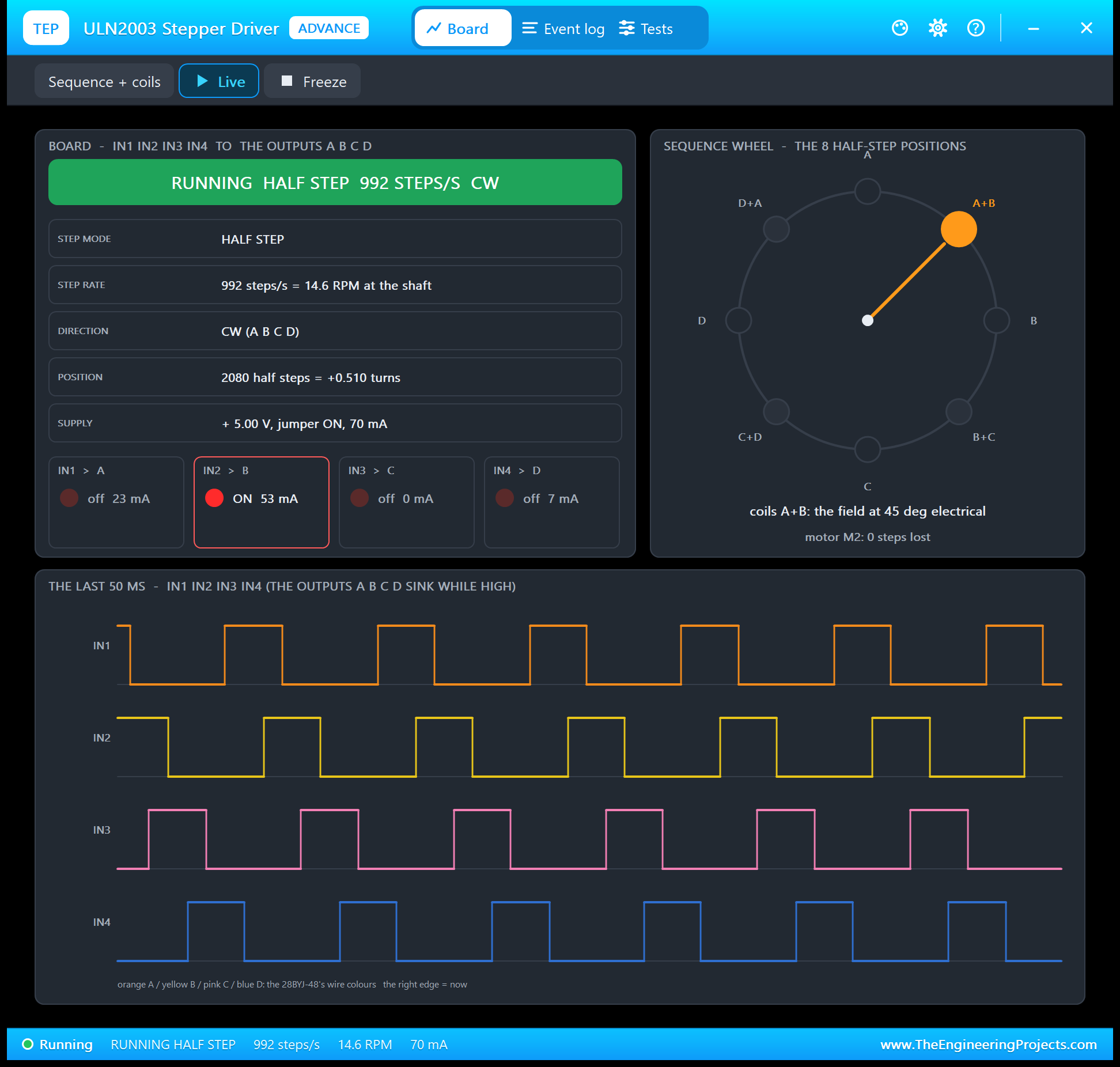
The left card is the board: the state in big letters, the step mode, the step rate in steps per second and RPM at the shaft, the direction, the position and the supply. Under them are the four channels, IN1 to A up to IN4 to D, each with its LED and its coil current. The right card is the sequence wheel: the eight half step positions around a circle, A at the top, and an orange pointer at the field the coils make now. At the bottom are the last 50 ms of IN1 to IN4.
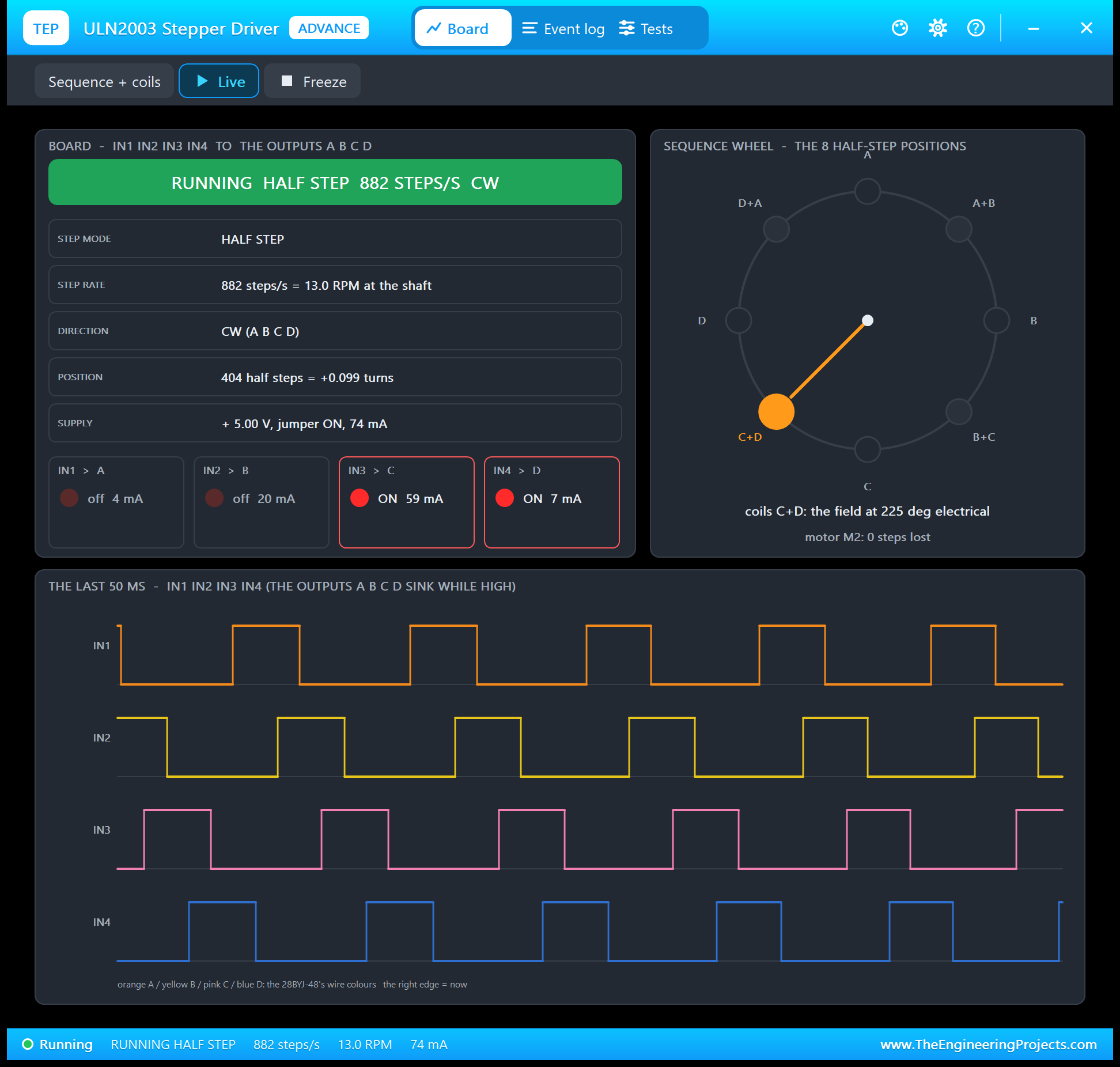
Read the traces from left to right and you see the half step sequence: IN1 alone, IN1 and IN2, IN2 alone, IN2 and IN3, and so on. In full step, two inputs are always HIGH and the traces overlap by half. Freeze holds the page for a closer look.
Event Log
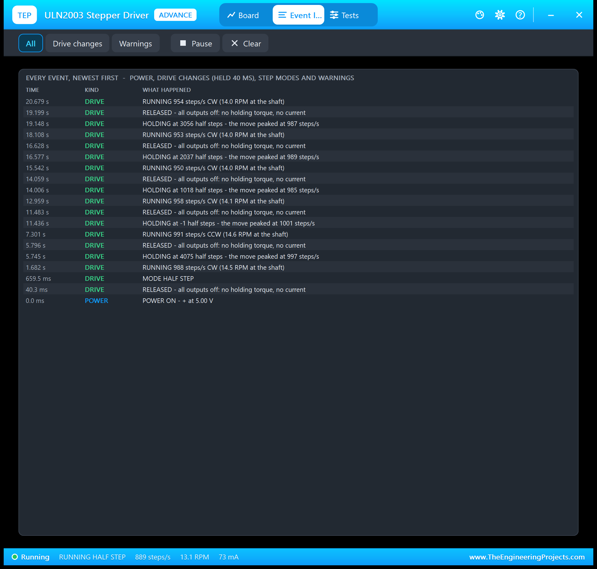
The Event log lists power on and off, the jumper, the step mode, the drive changes that held for 40 ms and the warnings. A move writes RUNNING once its speed has been steady for 100 ms, HOLDING when it ends, with the top speed of the move, and RELEASED when the sketch switches the coils off, for example "HOLDING at 4075 half steps - the move peaked at 997 steps/s". The motor's lost steps appear as warnings. Filter the log by drive changes or warnings, pause it, or clear it.
The Test Tools
The Tests tab holds three tools. Each one reads the board as the model sees it, and where it judges, gives every row a green, amber or red verdict.
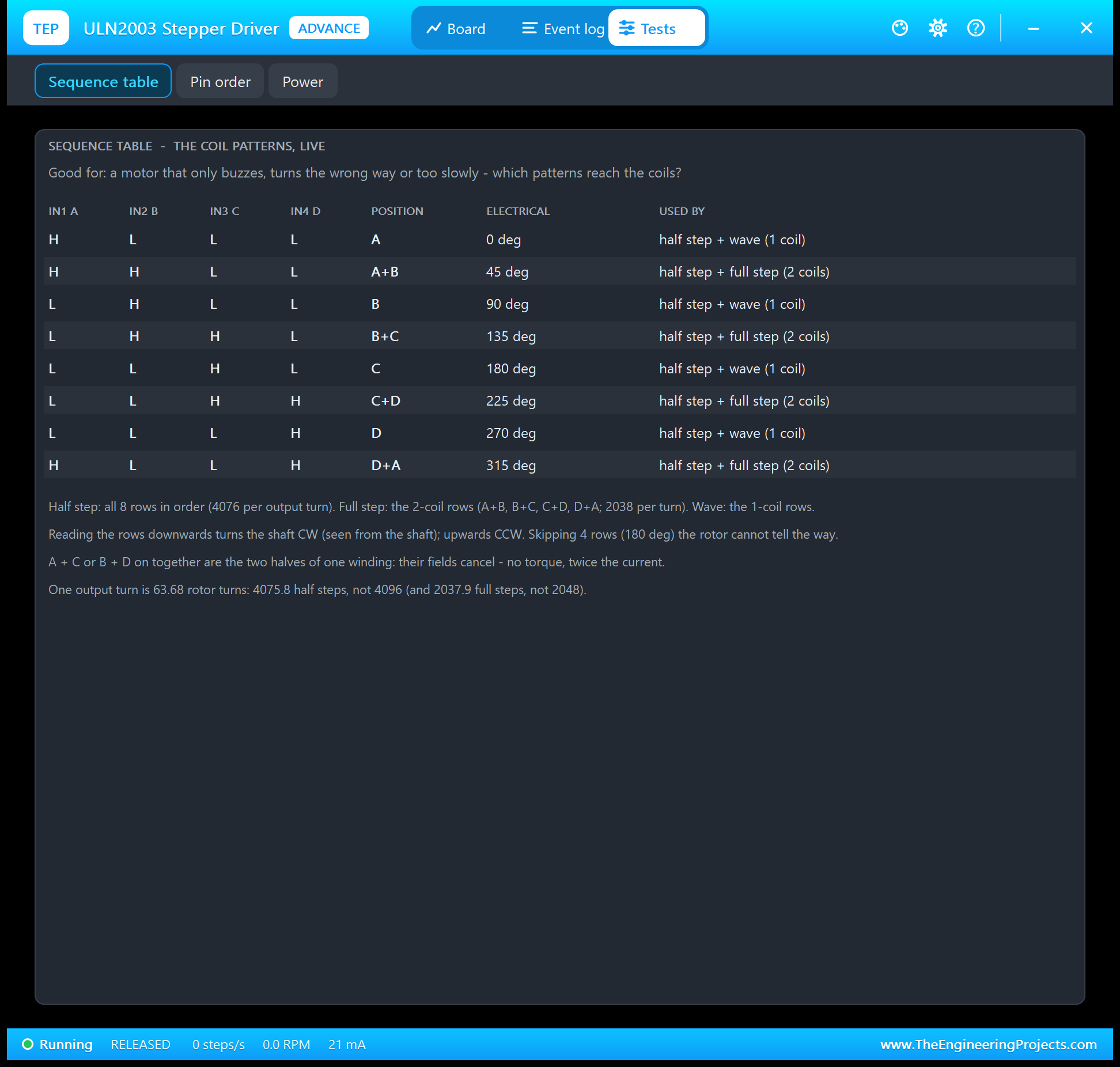
Sequence table is good for a motor that only buzzes, turns the wrong way or too slowly. It lists the eight half step rows with the input pattern, the position from A to D+A, the electrical angle in steps of 45 degrees and which step modes use the row, and highlights the row on the outputs right now. Under it are the rules: read the rows downwards for clockwise, the 2-coil rows for full step, and the gear ratio.
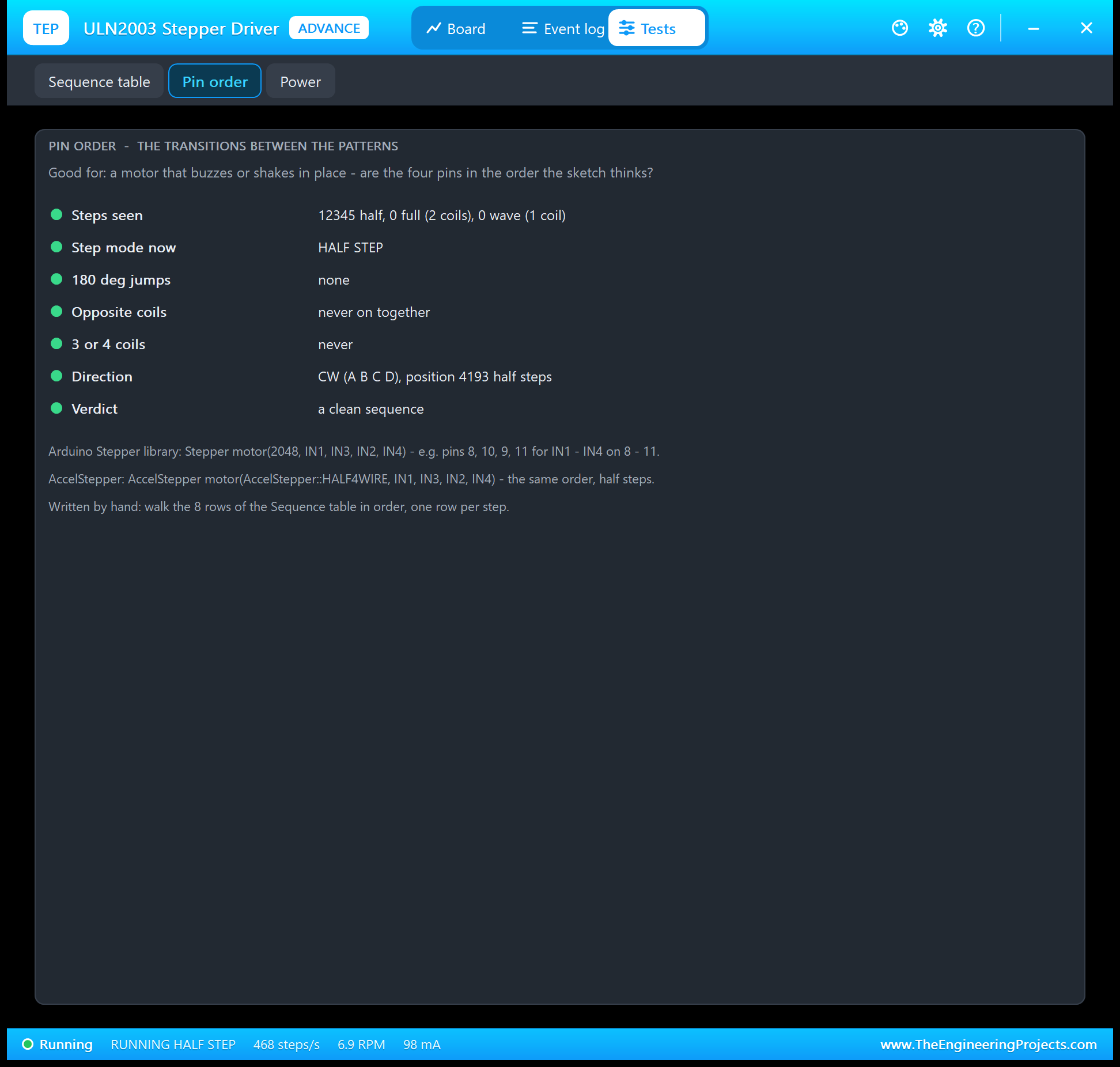
Pin order is good for a motor that buzzes or shakes in place. It counts the steps it has seen in each mode, the 180 degree jumps, the times opposite coils were on together and the patterns with three or four coils, shows the direction and the position and gives a verdict. Under it, it reminds you of the right pin order for the Stepper library and AccelStepper.
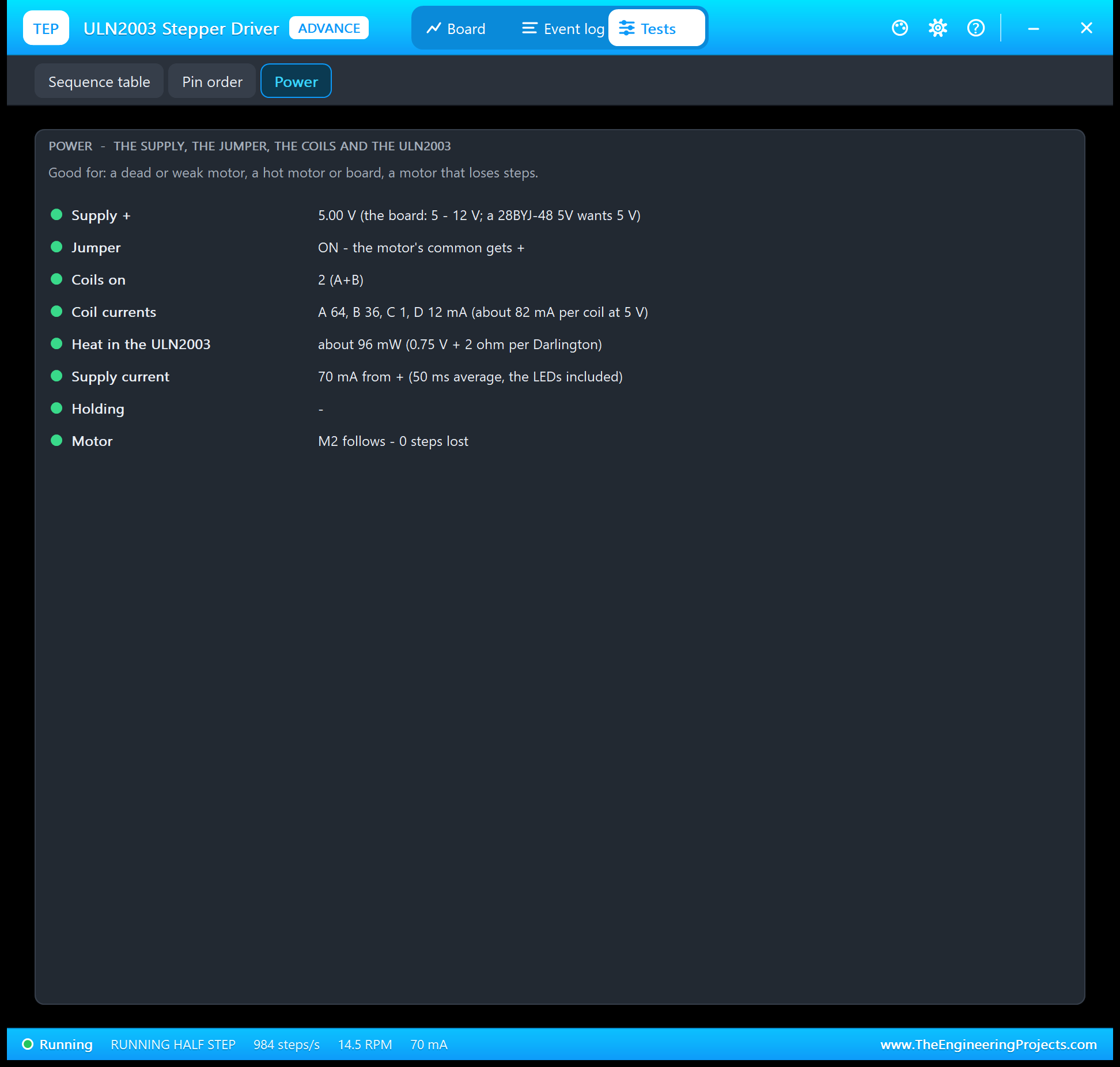
Power is good for a dead or weak motor, a hot motor or board, or a motor that loses steps. It shows the supply against 5 - 12 V, the jumper, the coils on, the four coil currents, the heat in the ULN2003 from its 0.75 V Darlington drop, the supply current with the LEDs, how long the coils have been holding, and the motor's lost steps.
The Wrong Pin Order: Why a 28BYJ-48 Only Buzzes
Type WRONG in node 2's monitor and the sketch makes 512 steps with Stepper(2048, IN1, IN2, IN3, IN4), the order almost everybody tries first. The Stepper library switches its four pins in the order 1010, 0110, 0101, 1001. With the pins in the natural order, that means A+C, then B+C, then B+D, then D+A. A+C and B+D are the two halves of the same winding: their fields cancel, so there is no torque at all. And B+C to D+A is a jump of exactly 180 degrees, where the rotor cannot tell which way to go.
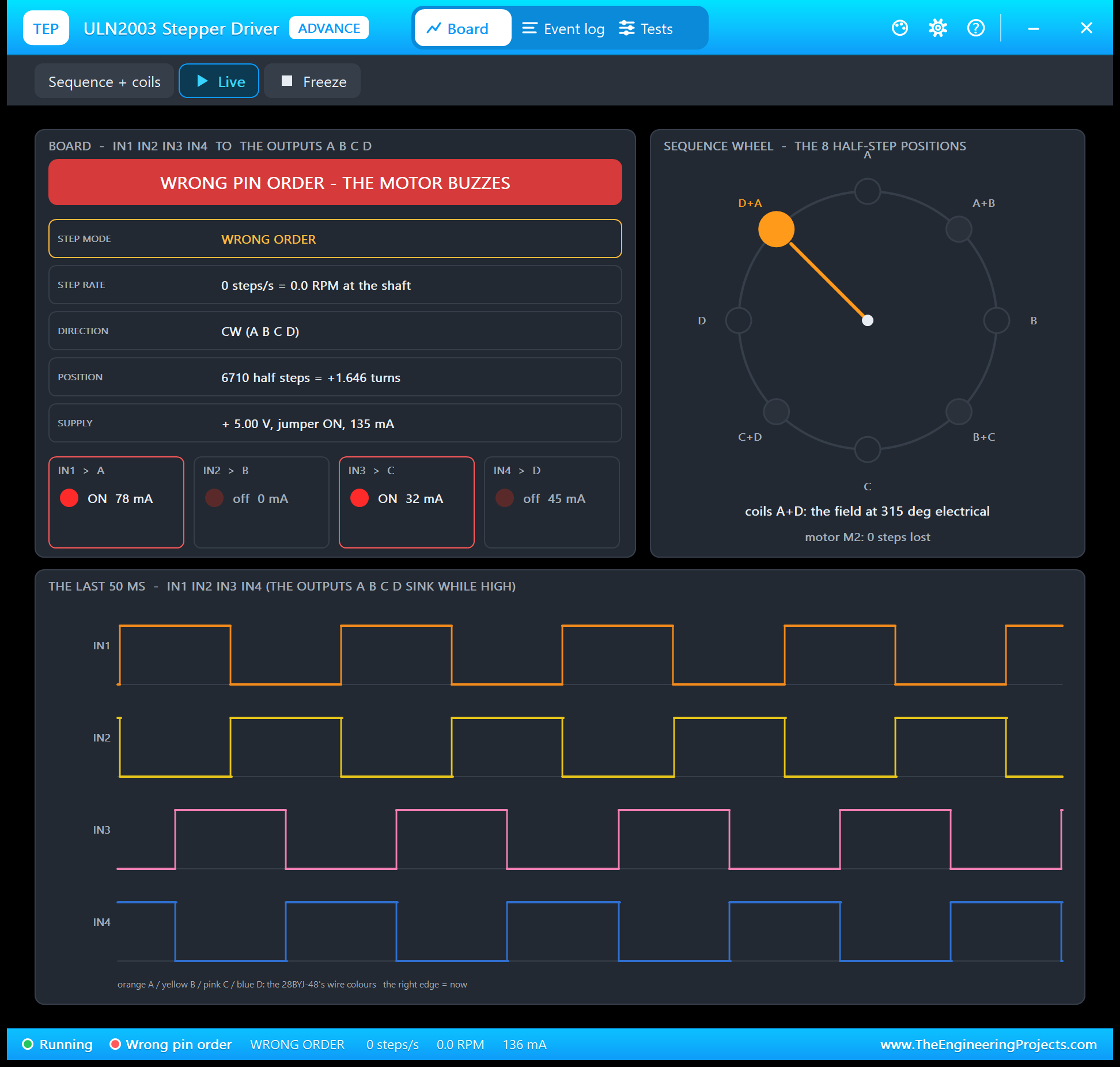
The board sees it at once. The banner turns red, the step mode says WRONG ORDER, and the position stays where it was: 6710 half steps. In the traces you find IN1 and IN3 HIGH together, and IN2 and IN4: patterns that should never appear.
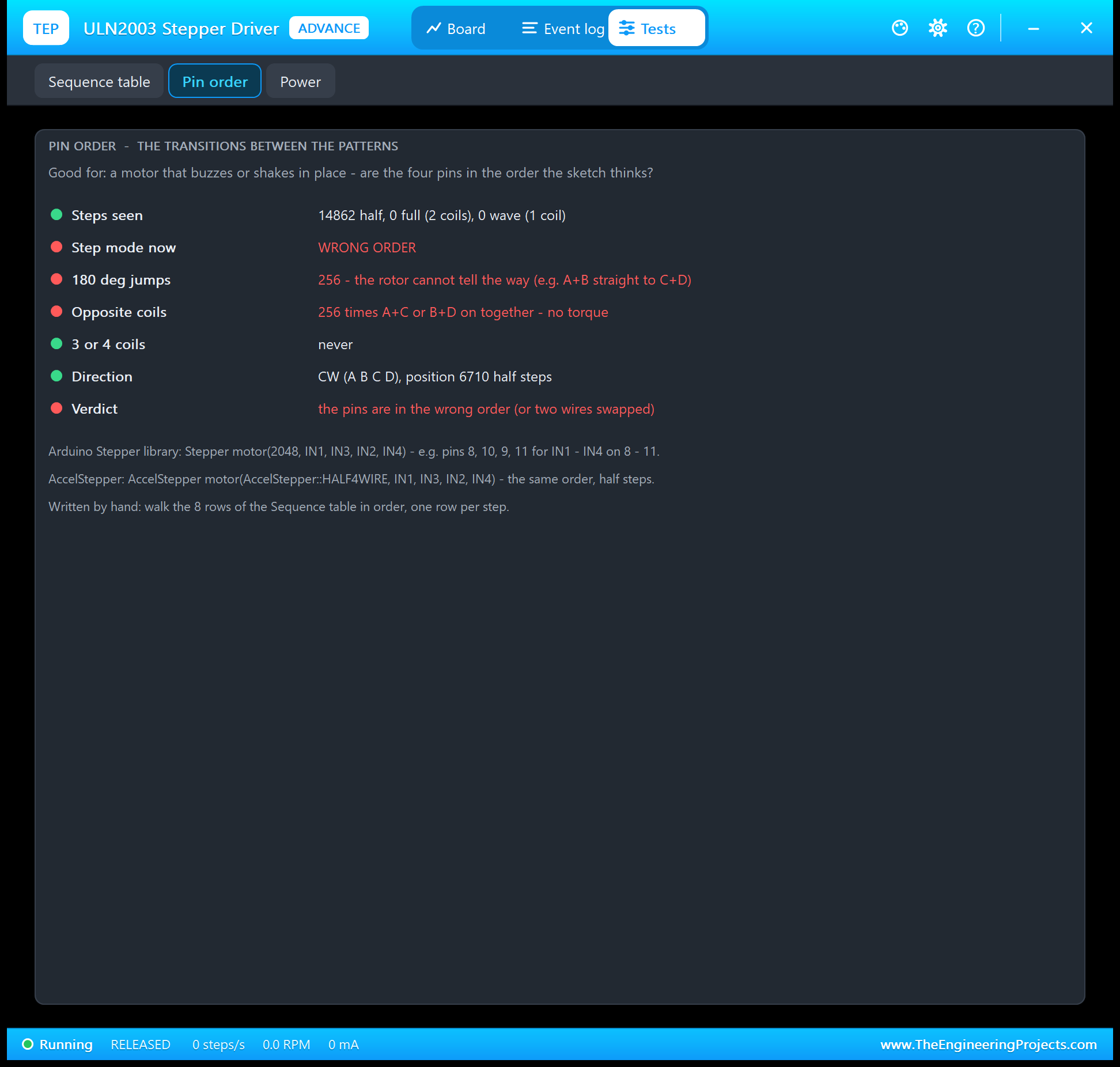
After the 512 steps, the Pin order tool counts 256 jumps of 180 degrees and 256 opposite coil patterns, and its verdict is red: the pins are in the wrong order, or two wires are swapped. The tips under it give the right order.
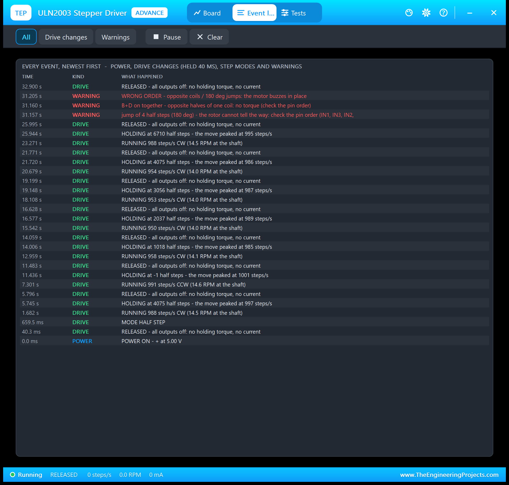
The Event log has the warnings with their reasons, for example "B+D on together - opposite halves of one coil: no torque (check the pin order)". And the motor? It hummed in place: the dial stayed on 232.7 degrees with 0 steps lost, while the sketch printed that the shaft should have turned 90 degrees:
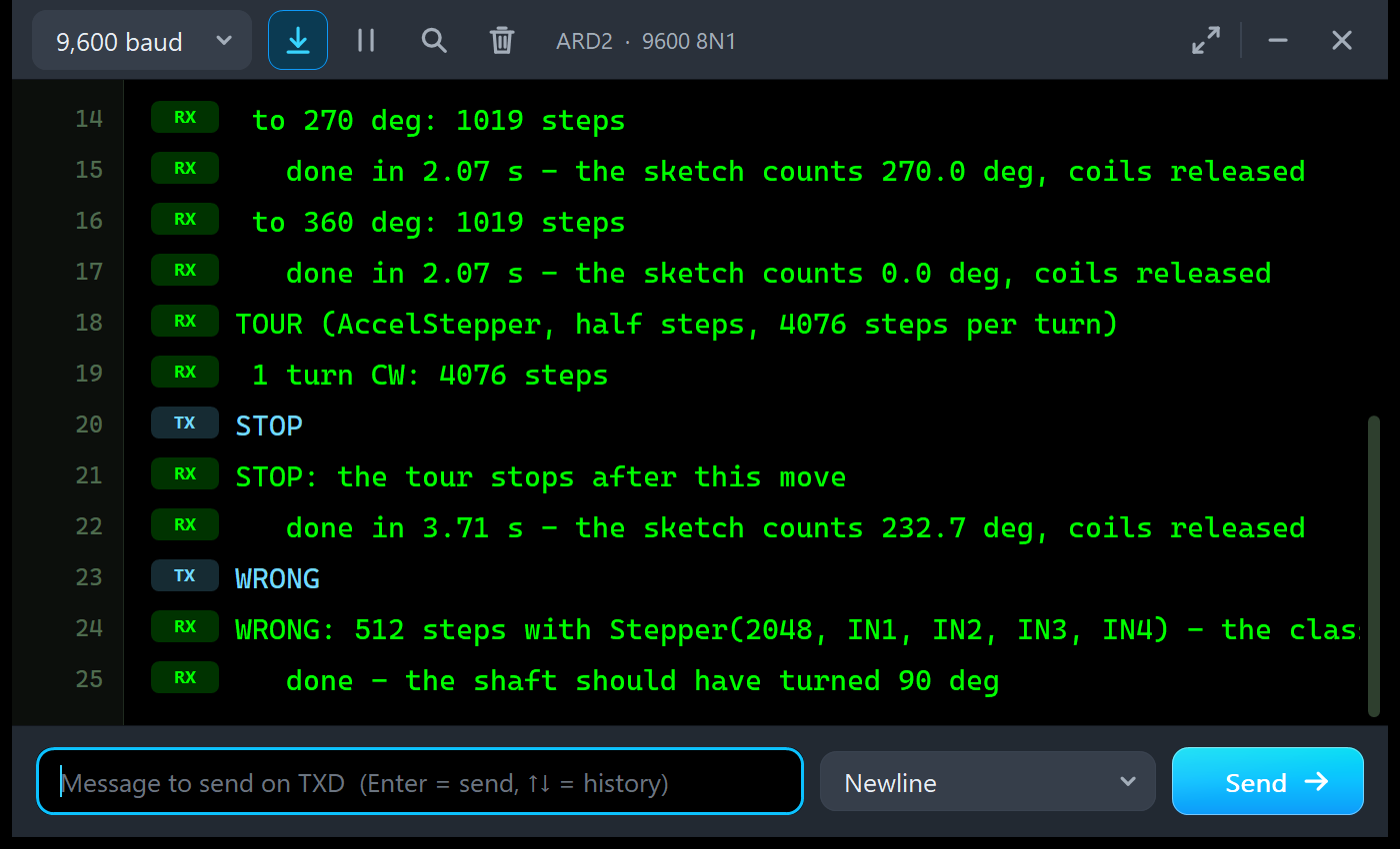
STOP
STOP: the tour stops after this move
   done in 3.71 s - the sketch counts 232.7 deg, coils released
WRONG
WRONG: 512 steps with Stepper(2048, IN1, IN2, IN3, IN4) - the classic pin order mistake: the motor only buzzes
   done - the shaft should have turned 90 deg
On a real board you hear a hum and feel the shaft tremble. If that happens, swap the two middle pins in your code, IN2 and IN3, and it runs.
The Serial Monitor
Both UNOs have the serial monitor built in, and it opens at Run. The screenshots use its Simple interface. Node 1 prints the tour like this:
TOUR (Stepper library, full steps, 2048 steps per turn)
 1 turn CW: 2048 steps
   done in 6.10 s - the sketch counts 0.0 deg, coils released
 1 turn CCW: -2048 steps
   done in 6.10 s - the sketch counts 0.0 deg, coils released
 to 90 deg: 512 steps
   done in 1.60 s - the sketch counts 90.0 deg, coils released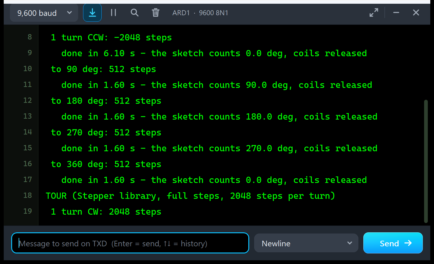
Every move prints its steps, and when it ends, the time it took and the angle the sketch believes. Node 2 shows the quarter turns of AccelStepper:
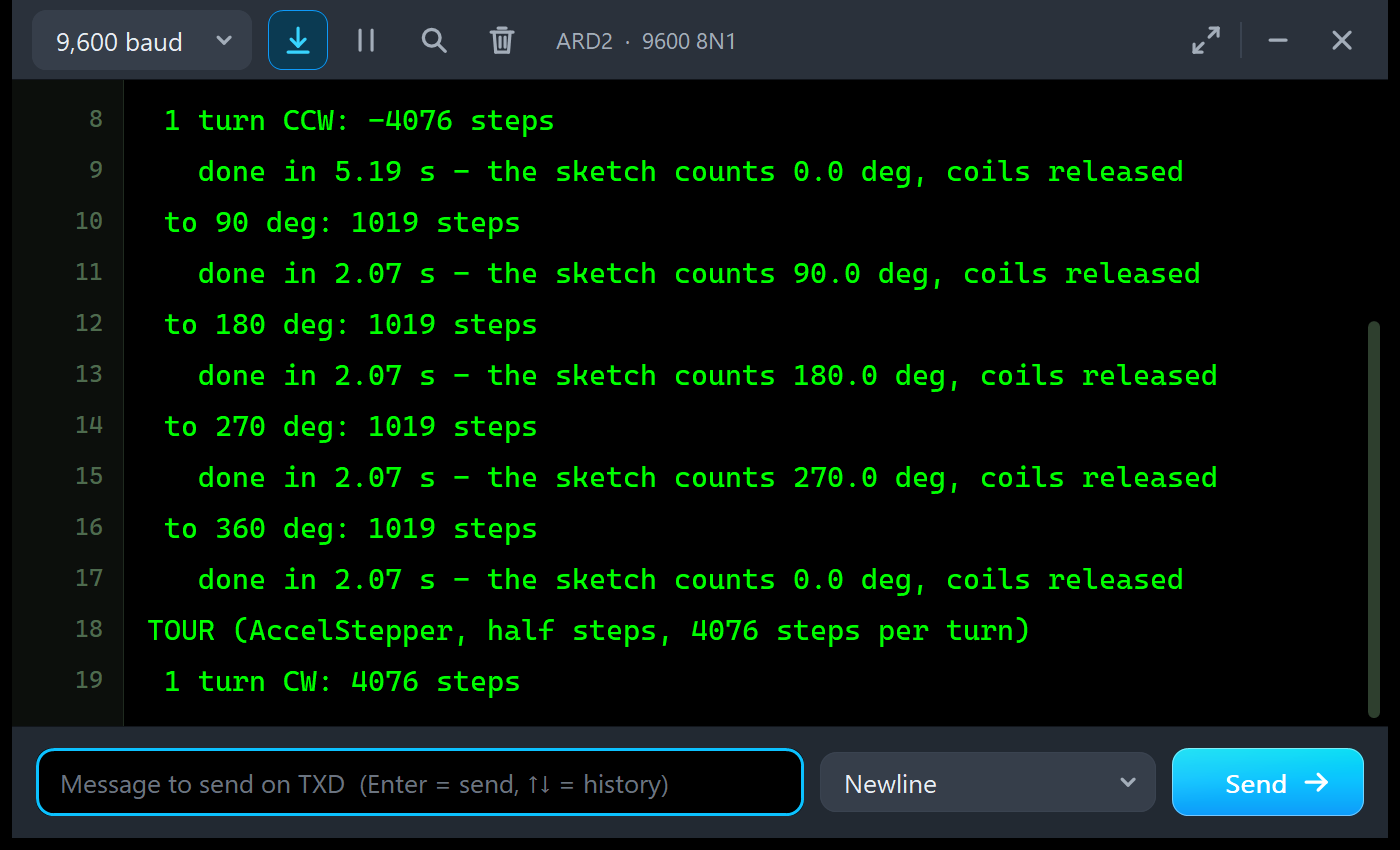
 to 90 deg: 1019 steps
   done in 2.07 s - the sketch counts 90.0 deg, coils released
 to 180 deg: 1019 steps
   done in 2.07 s - the sketch counts 180.0 deg, coils released
Commands
Type a command in the monitor and press Enter. STOP stops the tour after the move, MOVE 512 makes a relative move, GOTO 90 turns to an angle, SPEED changes the speed (RPM for the Stepper library, half steps per second for AccelStepper), RELEASE switches all outputs off, WHERE prints the angle the sketch believes, WRONG shows the classic mistake, RUN starts the tour again and HELP lists them. The Stepper library blocks during a move, so on node 1 a command is read when the move ends. At the end of the run, on node 1:
STOP
   done in 1.60 s - the sketch counts 90.0 deg, coils released
STOP: the tour stops after this move
WHERE
The sketch counts 90.0 deg (2560 steps)
The Simulation Log
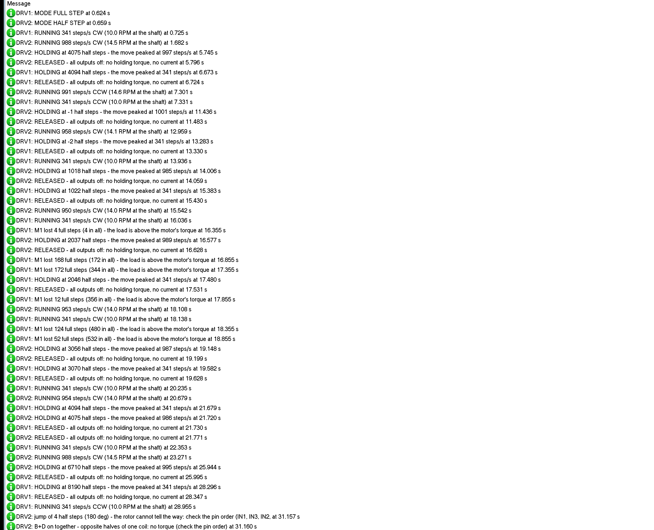
Each board writes its step mode and every drive change to the simulation log, for example "DRV1: RUNNING 341 steps/s CW (10.0 RPM at the shaft)" and "DRV2: HOLDING at 4075 half steps - the move peaked at 997 steps/s". The lost steps of a motor appear with their reason, and the wrong pin order with its warnings.
How the Board and the Motor Work Together
Proteus solves the analog part of a circuit in time steps and runs the digital part, here the Arduino's writes to IN1 to IN4, between them. A half step at 1000 per second lasts only 1 ms, and the motor must follow every one at the right moment. So the board keeps each input edge with its exact time, and the motor, which finds its board through the wires on its pins, integrates its coils and rotor over every analog step in 10 us pieces from that history. The coil currents go back into the circuit, so the + of the board really draws them.
A sketch writes the four pins one after the other, so for a few microseconds between two steps the outputs show patterns that are neither the old step nor the new one. A real motor ignores them, because a 60 mH coil cannot change its current that fast. The board ignores them too: a pattern only counts once it has held for 50 us. That is how the Pin order tool tells a clean sequence from a wrong one without false alarms.
Inside the motor, each coil current rises against the coil's resistance, its inductance and the back-EMF of the turning rotor, and when an output switches off, the current runs on through the board's clamp diode until it dies away. The rotor is pulled by the field of the four currents, held between steps by the detent of its magnet, slowed by friction, and turns the shaft through the gearbox. At higher speeds the coils cannot build up their current any more and the torque drops: on a PC, the unloaded motor kept every step up to 1200 half steps per second with a ramp, but with a 20 mN.m load only up to 600.
Troubleshooting
- The motor never moves and the ON LED is dark: no supply on + (NO SUPPLY in the banner).
- The LEDs walk but the motor does not move: the jumper is OFF (JUMPER OFF in the banner), so the motor's common gets no power.
- The LEDs blink but the motor only buzzes or shakes: the pin order; use IN1, IN3, IN2, IN4 with the Stepper library and AccelStepper. The Pin order tool shows the 180 degree jumps and the opposite coils.
- The motor turns a little too far every turn: 2048 steps is not one turn; one output turn is 2037.9 full or 4075.8 half steps.
- The motor turns the wrong way: use a negative step count, or reverse the pin order (IN4, IN2, IN3, IN1).
- LOST counts up: the load is above the motor's torque or the speed is too high; the 28BYJ-48 is slow, about 10 - 15 RPM, so start slower or use AccelStepper's acceleration.
- No part, no dial or no monitor: TEPULN2003.DLL or TEPARDUINO.DLL is missing from MODELS and the project folder; a closed monitor opens again with a click on the UNO's USB port.
Things to Know Before Using a Real 28BYJ-48 and ULN2003
- The supply: one 28BYJ-48 holding with two coils draws about 160 mA. The Arduino's 5V pin can feed one motor from a good USB port; for more motors use a separate 5 V supply, with its GND joined to the Arduino's.
- 5 V or 12 V: the 28BYJ-48 comes in a 5 V and a 12 V version; check the label on the can. This model is the 5 V motor.
- Release the coils: a 28BYJ-48 that holds its position for a long time gets warm. If it does not need to hold, write all four inputs LOW, as our demo does after every move.
- Gearbox play: the plastic gears have 1 to 3 degrees of play; when the position matters, come to it from the same side.
- Count right: for many turns, count in half steps and convert with 4075.77 per turn, or the error grows by 1.79 degrees every turn.
Limitations of the Simulation
- The coil volts and amps on the schematic's wires are averages of each analog step.
- Not modelled: the gearbox play, the 12 V version of the motor, magnetic saturation, heating, the ULN2003's thermal limits and its 500 mA per channel maximum, and damage from a wrong supply (the model warns about a long hold).
- A 28BYJ-48 on its own, without a TEP ULN2003 on its wires, is driven from the voltages of its wires.
- The strip, its LEDs, the panels, the dial and the LOAD button are TEP additions.
- The model is our own, written from the ULN2003 datasheets and typical data of the 28BYJ-48 5V and its board; this library is not made or endorsed by Texas Instruments, Toshiba, the makers of the 28BYJ-48 or its boards, or Labcenter.
- Licences: the demo sketch uses AccelStepper (GPL-3.0), so the sketch is GPL-3.0 too; both are in the zip. The HEX file also contains the Arduino Stepper library (LGPL) and the Arduino AVR core 1.8.6 with LGPL-licensed code; their source links are in the README.
- Tested in Proteus 8.5 in October 2026 (the demo as shipped on two Arduino UNO V4.0 boards with their built-in monitors: the tour on both nodes, the LOAD button, the WRONG command, the commands, the pop-up and the three tools; about 0.43 x real time with the pop-up and both monitors open). Proteus 7 is not supported.
So, that was all about the 28BYJ-48 Stepper Motor and ULN2003 Driver Library for Proteus V1.0. I hope the step modes, the real gear ratio, the pin order and the danger of lost steps are clear now, so your 28BYJ-48 turns smoothly from its first run. If you use the 28BYJ-48 Stepper Motor and ULN2003 Driver Library for Proteus in a project, please share it in the comments or in our forum, and if you have any questions, ask in the comments and I will help you out. Till the next tutorial, take care and have fun!