Hello friends, I hope you all are doing great. Today, I am going to share the new DS18B20 Library for Proteus V1.0. The DS18B20 is the digital thermometer of countless aquariums, freezers, brewing kettles, greenhouses and weather stations. It needs only one data wire, several of them can share that wire, and in its stainless steel waterproof probe it goes straight into water or soil. Now you can build and test it in Proteus, as the black TO-92 part and as the probe on its cable.
Behind the parts sits our own model of the chip, not a part that shows a number. It speaks the real 1-Wire protocol: it answers the reset pulse with a presence pulse, reads the Arduino's write slots, drives its 0s in the read slots, and knows the ROM and function commands. Each sensor has its own 64-bit ROM code, so two or more on one wire are found by the search and read by their addresses, exactly like real ones. Parasite power works too, with its classic trap. You get four devices: the TO-92 and the probe, each as a Simple device with a live STATUS panel and temperature controls, and as an Advance device with a pop-up window and three test tools. The demo runs the OneWire library and the DallasTemperature library on our Arduino UNO V4.0.
NOTICE: a temperature sensor is easy to fake: read a number from a property and hand it to the Arduino. We wanted more. Our DS18B20 answers the real 1-Wire slots, bit by bit, so OneWire and DallasTemperature find it, address it and read it exactly as on your desk, and the classic mistakes fail exactly as they do there. It took our team a lot of hard work. Your feedback is the fuel that keeps us going, so please tell us what you think in the comments below or in the DS18B20 board of our forum. And if our free libraries help you, you can buy us a coffee. So, let's get started with the DS18B20 Library for Proteus V1.0:
What is the DS18B20?
The DS18B20 is a digital thermometer from Maxim, the former Dallas Semiconductor. It measures -55 to 125 C, with an accuracy of 0.5 C from -10 to 85 C, and sends the result as a 9 to 12-bit number over one data wire, DQ. Inside are the temperature sensor, an analog-to-digital converter, a small memory called the scratchpad, three bytes of EEPROM and a laser-programmed 64-bit ROM code that no other DS18B20 shares. The TO-92 part looks like a transistor; the waterproof probe is the same chip sealed in a stainless steel tube on a cable. For the chip itself, read our Introduction to DS18B20; for several sensors on real hardware, our Interfacing of Multiple DS18B20 Arduino.
| DS18B20 | |
|---|---|
| Temperature | -55 to 125 C, +-0.5 C from -10 to 85 C |
| Resolution | 9, 10, 11 or 12 bits: steps of 0.5, 0.25, 0.125 or 0.0625 C |
| Conversion time | 93.75, 187.5, 375 or 750 ms |
| Supply | 3.0 to 5.5 V on VDD, or parasite power from DQ (VDD to GND) |
| Bus | 1-Wire on DQ, open drain, one 4.7 kohm pull-up per wire |
| Address | a 64-bit ROM code: family 28, a 48-bit serial, a CRC |
| Pins | GND, DQ, VDD; the probe's wires: black GND, yellow DQ, red VDD |
| Devices | DS18B20TEP and DS18B20PROBETEP (Simple), DS18B20ADVTEP and DS18B20PROBEADVTEP (Advance) |
How the 1-Wire Bus Works
The bus has one wire and a pull-up resistor, so it rests HIGH. The DS18B20, like the Arduino, only pulls DQ LOW or lets it go; the resistor does the rest. Every conversation starts with a reset: the Arduino holds DQ LOW for at least 480 us, and every sensor on the wire answers with a presence pulse, a LOW of 60 to 240 us. After that, every bit is a time slot that starts when the Arduino pulls DQ LOW. To write a 1, it lets go within 15 us; to write a 0, it holds DQ LOW for 60 us or more, and the sensor samples DQ in between. To read a bit, it pulls DQ LOW for a moment and lets go: a sensor that sends a 0 holds DQ LOW a little longer, and the Arduino samples it within 15 us. Bytes go least significant bit first.
The ROM Code and the Commands
After the reset comes a ROM command that says which sensor should listen. SKIP ROM (CC) addresses all of them at once, MATCH ROM (55) one of them by its 8-byte code, READ ROM (33) asks for the code of the only sensor on the wire, and SEARCH ROM (F0) finds every code bit by bit: each sensor sends the bit and its complement, the wire ANDs them, and the Arduino picks a direction. Then a function command follows: CONVERT T (44) starts a measurement, READ SCRATCHPAD (BE) sends the 9 bytes of the result with a CRC, WRITE SCRATCHPAD (4E) sets the alarm limits and the resolution, and COPY SCRATCHPAD (48) saves them in the EEPROM.
Parasite Power
The DS18B20 can even run without VDD. With VDD tied to GND, it charges a small capacitor from DQ while the line is HIGH. That works for the short slots, but a conversion needs about 1 mA for up to 750 ms, so the Arduino must hold DQ HIGH for the whole conversion. If anything pulls DQ LOW too early, the sensor loses its power and starts again with the power-on value of 85 C. The library's READ POWER SUPPLY command (B4) tells the Arduino which mode it has.
What's New in DS18B20 Library for Proteus V1.0
- Two real parts: the black TO-92 with its print and bent legs, and the stainless steel waterproof probe with its cable and the red, yellow and black wires.
- Two styles: each part as a Simple device with a STATUS panel and as an Advance device with a pop-up window.
- The real protocol: reset and presence, write and read slots with the datasheet's timing, all ROM and function commands, the scratchpad and the ROM code with their CRCs.
- Several sensors on one wire: each with its own ROM code, found by the search and read by its address.
- The real behaviour: 9 to 12 bits with their conversion times, the power-on 85 C, the alarm flag, the EEPROM, VDD or parasite power.
- Temperature controls: - / + buttons and six presets, on the panel or in the pop-up, while the simulation runs.
- Mistake detection: no pull-up, Skip ROM with several sensors, a read before the conversion, DQ pulled LOW during a parasite conversion, VDD too low.
- Three test tools on the Advance devices: Bus, Power and Scratchpad.
- A two-node demo on our Arduino UNO V4.0 with OneWire and DallasTemperature: two sensors on one wire on each node, powered from 5 V on node 1 and on parasite power on node 2.
- A compact package: about 1.26 MB, without the C++ source code of the model.
Four Devices: Two Parts, Simple and Advance
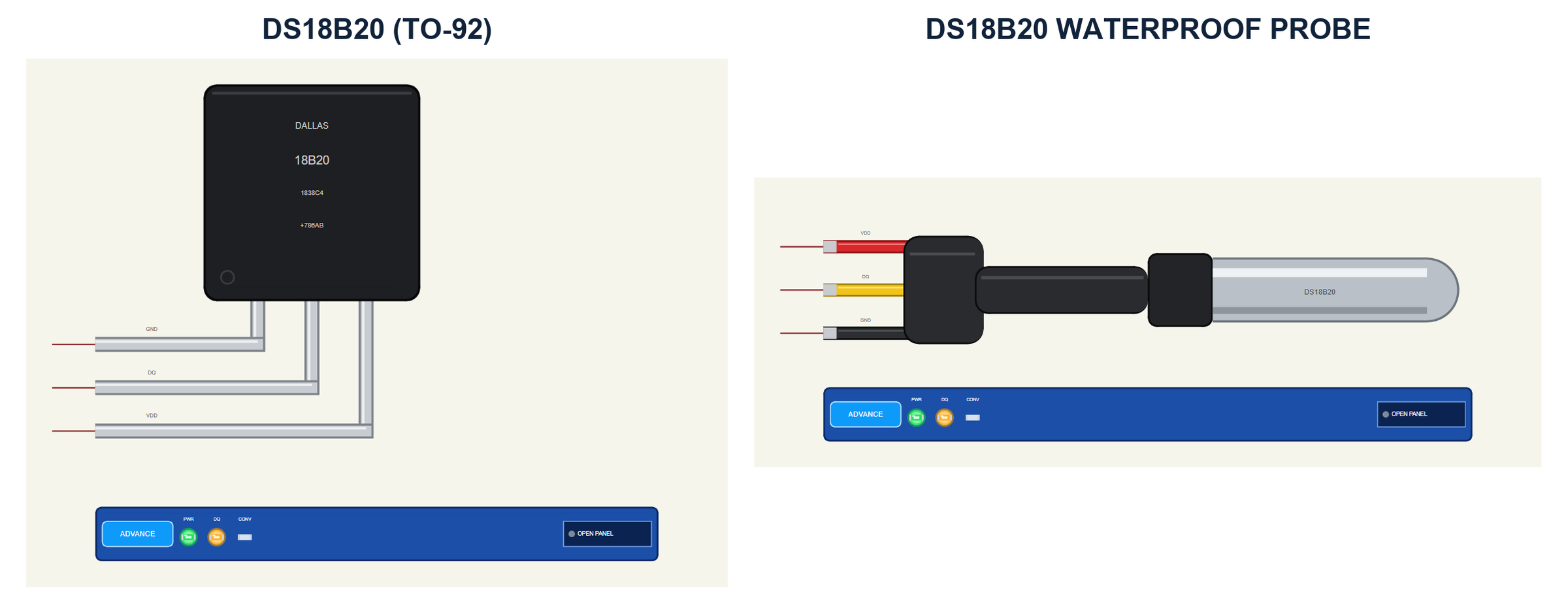
The parts look like the ones in your drawer. The TO-92 shows its flat face with the print DALLAS 18B20, drawn about five times its real size; its three legs, GND, DQ and VDD, bend to the pins on the left. The probe is drawn at about half its real length: the stainless steel tube with its round tip, the heat-shrink sleeve, the black cable and the three wires, red VDD, yellow DQ and black GND, each with a tinned end at its pin.
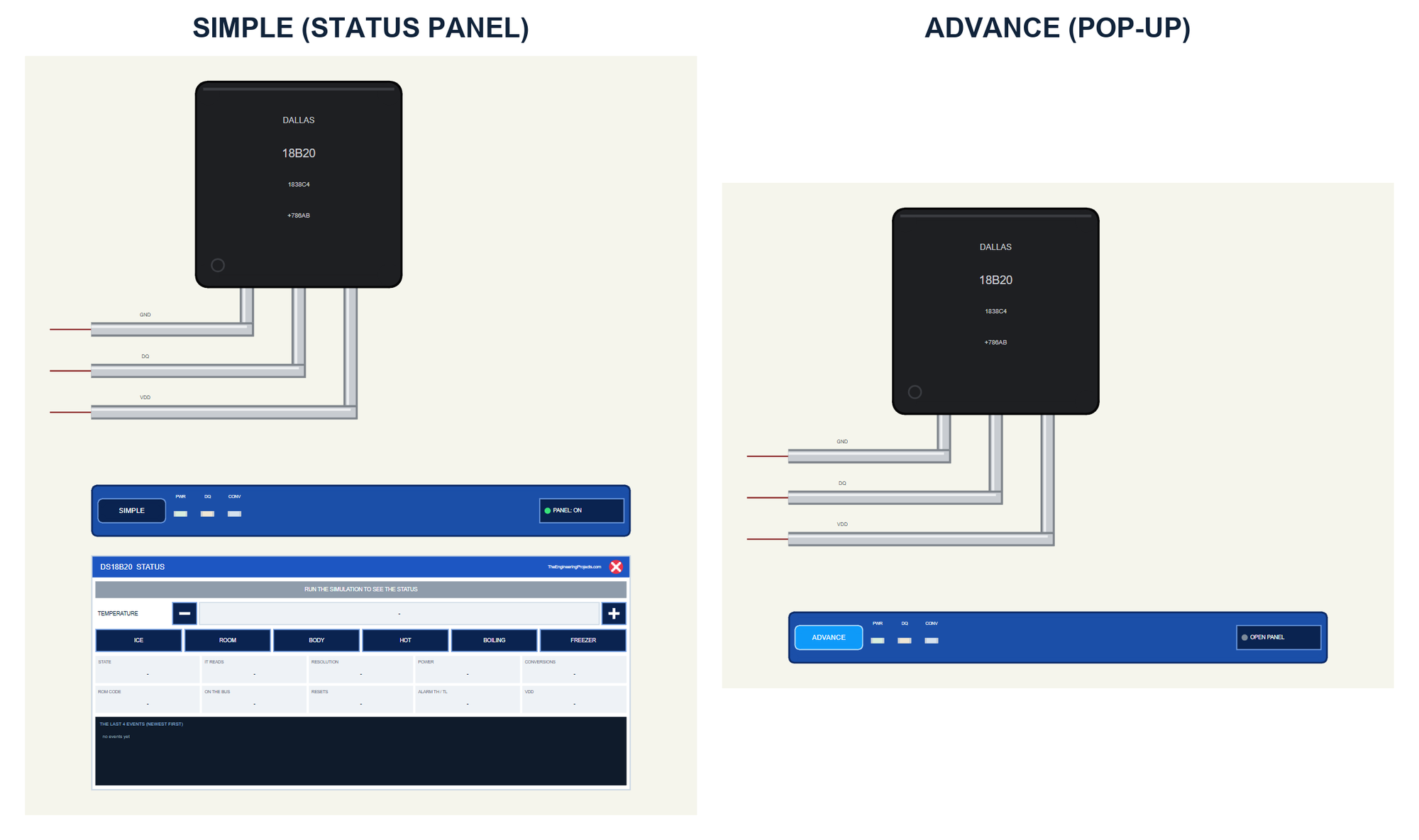
| Simple | Advance | |
|---|---|---|
| Devices | DS18B20TEP, DS18B20PROBETEP | DS18B20ADVTEP, DS18B20PROBEADVTEP |
| On the schematic | The part, its strip and the STATUS panel | The part and its strip |
| The temperature | TEMPERATURE - / + and six presets on the panel | The same in the pop-up |
| Status | Banner, 10 readouts, the last 4 events | A pop-up: Sensor, Event log, Tests |
| Interaction | The panel's buttons, PANEL on the strip | The pop-up, OPEN PANEL on the strip |
Download DS18B20 Library for Proteus
Click the button below to download DS18B20-Library-for-Proteus-v1.0.zip (about 1.26 MB, without the C++ source code of the model):
DS18B20 Library for Proteus V1.0: Waterproof Temperature Sensor- README.txt: the devices, installation, the demo, wiring, the test tools and real hardware.
- Proteus Library Files:
TEPDS18B20.LIBandArduinoV4TEP.LIBfrom our Arduino Library for Proteus V4.0. - Proteus Model Files:
TEPDS18B20.DLLandTEPARDUINO.DLL. - Proteus Simulation:
DS18B20-ArduinoUnoV4.pdsprj,DS18B20_Demo.hexand copies of the two DLLs. - Arduino Code:
DS18B20_Demo.ino. It needs OneWire and DallasTemperature from the Library Manager of the Arduino IDE, only if you want to change the sketch.
No Proteus yet? Read How to Download and Install Proteus 7 and 8. New to libraries? Follow How to Install a New Library in Proteus.
How to Install DS18B20 Library for Proteus
- Close Proteus and extract the whole zip file, for example to your Desktop.
- Copy the two files from Proteus Library Files into the LIBRARY folder of Proteus (usually
C:\Program Files (x86)\Labcenter Electronics\Proteus 8 Professional\LIBRARY). - Copy
TEPDS18B20.DLLandTEPARDUINO.DLLfrom Proteus Model Files into the MODELS folder. - Delete
TEPDS18B20.IDXfrom the LIBRARY folder if it is there. - Start Proteus, press P and search for DS18B20.
Tip: keep the Proteus Simulation folder together, because the project needs its .hex file and the DLLs beside it. The library is tested in Proteus 8.5; Proteus 7 is not supported.
The DS18B20 Parts in Proteus
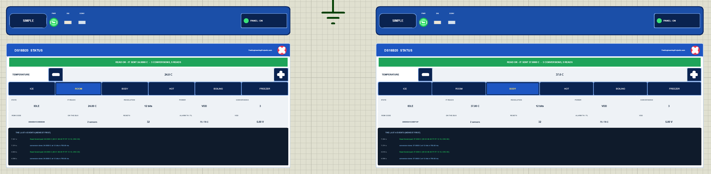
Under each part is the TEP strip with the SIMPLE or ADVANCE badge and three LEDs: PWR while the sensor has power, DQ while there is traffic on the bus, and CONV while it converts. The strip, its LEDs and the panels are TEP additions; the real sensors have none of them.
The Simple device adds the STATUS panel. Its banner says what happened last, for example "READ OK - IT SENT 24.0000 C - 5 CONVERSIONS, 7 READS", turns blue while the sensor converts and red with a warning. Under it is the TEMPERATURE with its - and + buttons (1 C a click) and six presets: ICE, ROOM, BODY, HOT, BOILING and FREEZER. Ten readouts follow: the state, what the sketch reads (the value DallasTemperature makes of the last read), the resolution, the power, the conversions, the ROM code, the sensors on the bus, the resets, the alarm limits TH and TL, and VDD. At the bottom are the last four events.
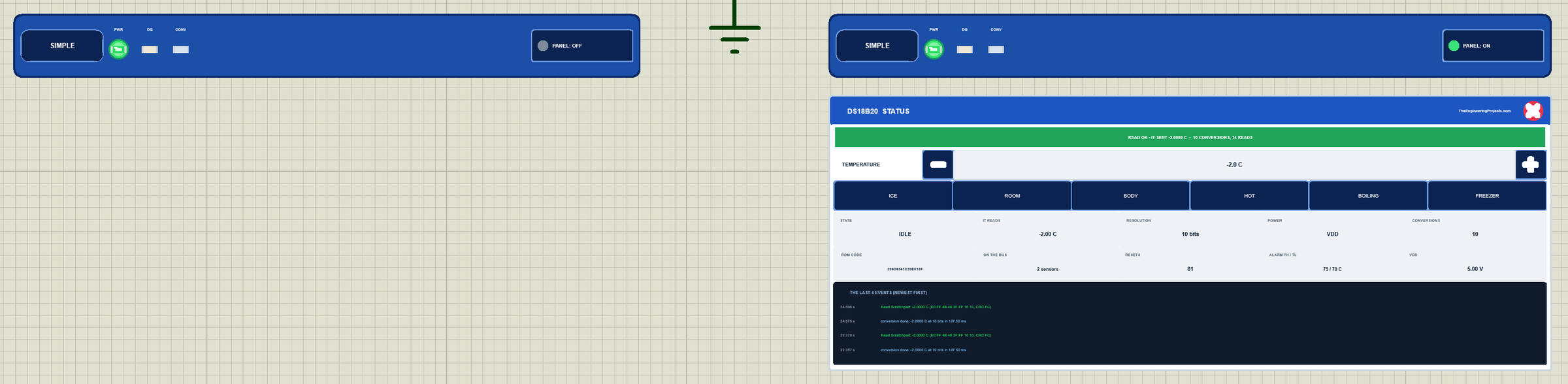
The red X closes the panel, and the PANEL button on the strip opens it again, so a big project stays readable:
The Advance device keeps the schematic clean: only the part and its strip. Its live data and its temperature controls open in a pop-up window at Run, and the OPEN PANEL button brings the window back if you close it. Three properties set the start: TEMPERATURE (24.0 C by default), SERIAL (the ROM code) and, on the Simple devices, PANEL (open or closed). With SERIAL at AUTO, each part makes its ROM code from its name, so every part on a wire has its own code, the same in every run.
The Demo Circuit
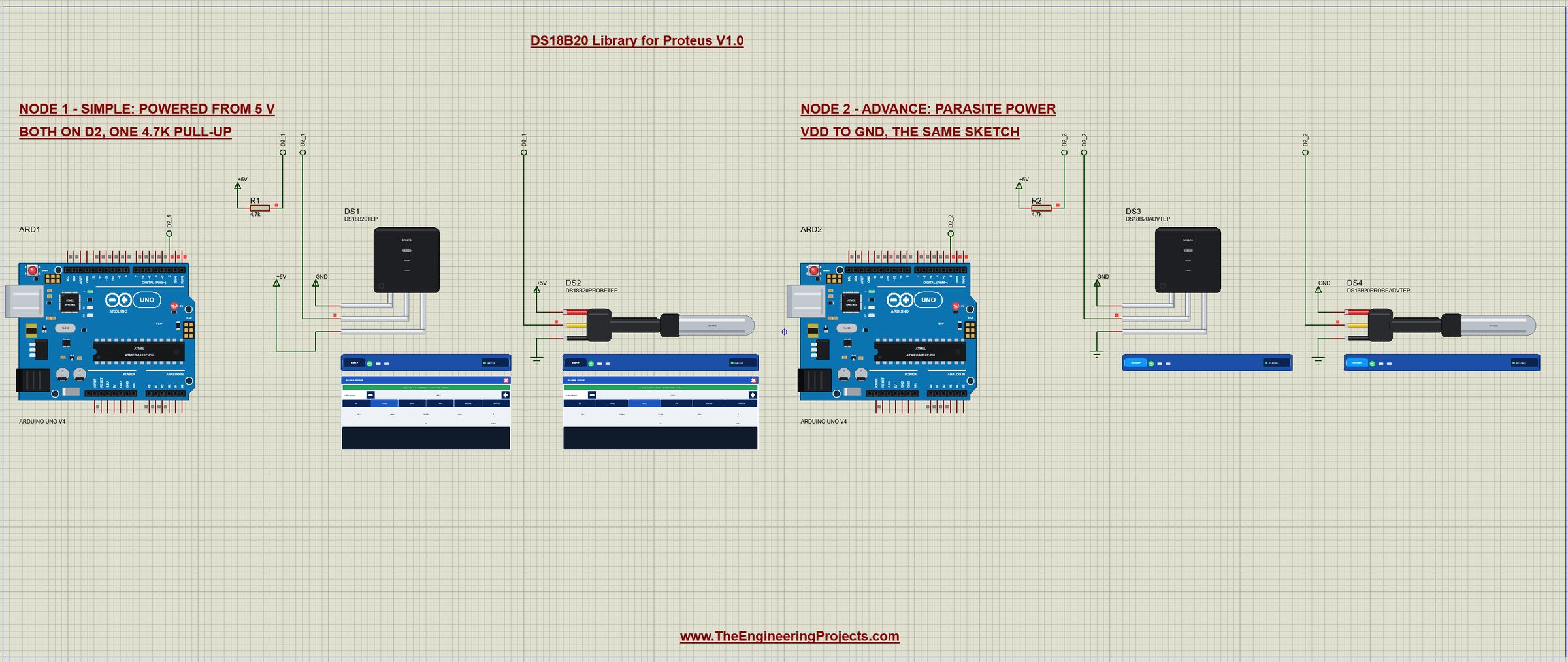
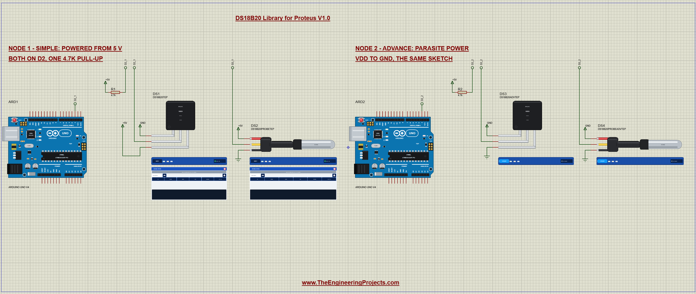
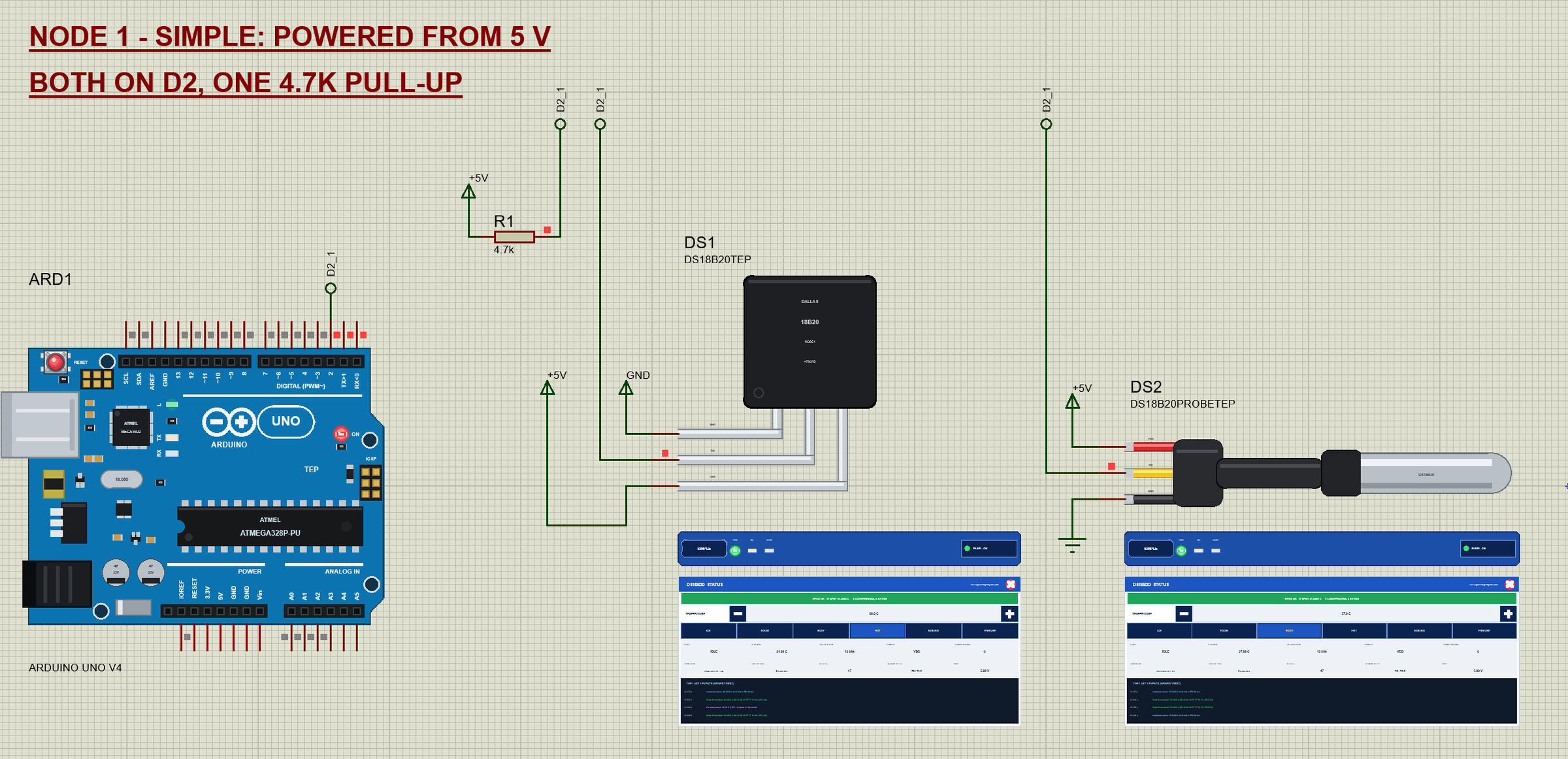
The demo project has two nodes. Each one is an Arduino UNO V4.0 from our Arduino UNO Library for Proteus V4.0 with two sensors on D2: a TO-92 and a waterproof probe on the same wire, with one 4.7 kohm pull-up. Both UNOs run the same DS18B20_Demo.hex. Node 1 uses the Simple devices, powered from 5 V; node 2 uses the Advance devices on parasite power, with VDD tied to GND.
Wiring
| DS18B20 | Arduino UNO | Note |
|---|---|---|
| VDD | 5V, or GND for parasite power | 3.3 V works too |
| DQ | D2 | any digital pin; ONE 4.7 kohm from DQ to 5V for the whole wire |
| GND | GND | common ground |
In Proteus every DQ pin reaches its UNO through a wire with a net label, D2_1 for node 1 and D2_2 for node 2, and so does the pull-up R1 or R2. The power pins go to +5V and GND terminals; on node 2 both VDD and GND go to GND. The serial monitor needs no wires at all, because it is built into the UNO V4.0. On the probe the wires are red for VDD, yellow for DQ and black for GND; on the TO-92, seen from its flat face with the legs down, the pins are GND, DQ and VDD from left to right.
Node 1: Two Sensors, One Pull-Up
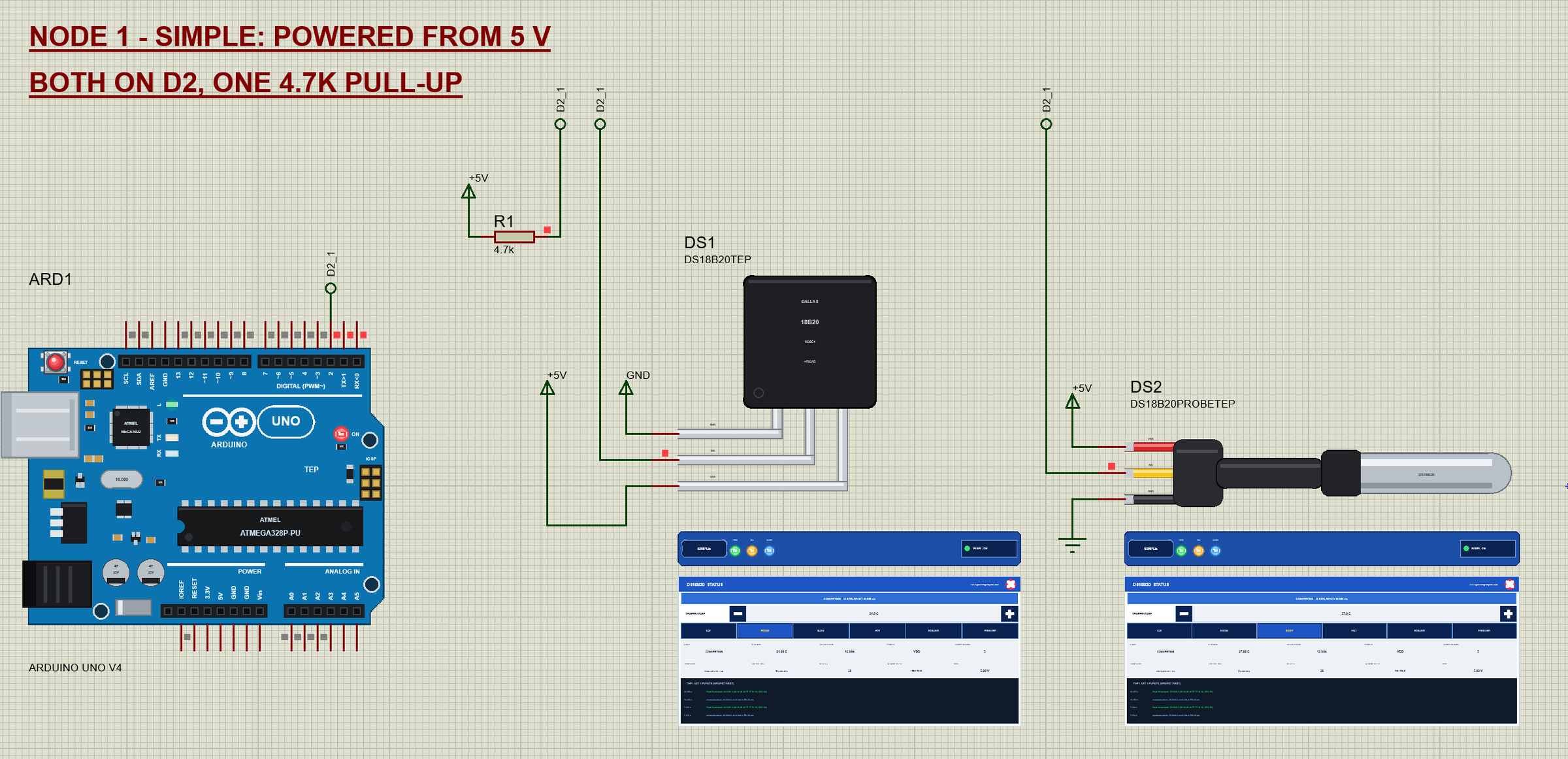
Node 1 shows the whole bus on the schematic: the UNO's D2, the pull-up from D2 to +5V, and two sensors whose DQ pins all carry the label D2_1. There is no address wiring at all; the two sensors tell themselves apart by their ROM codes.
The Arduino Code
The demo sketch uses the OneWire library (version 2.3.8) for the bus and the DallasTemperature library (version 4.0.6) for the sensor, the most common pair for the DS18B20. New to Arduino? Start with Arduino Tutorial for Beginners and Introduction to Arduino UNO. The sketch begins with the two libraries:
#include <OneWire.h>
#include <DallasTemperature.h>
Then the pin, the time between readings and room for three sensors:
const uint8_t ONE_WIRE_PIN = 2;                // DQ of every DS18B20
const unsigned long PERIOD = 2000;             // ms between two readings
const uint8_t MAX_SENSORS = 3;
One OneWire object for the wire, one DallasTemperature object on top of it, and an array for the ROM codes:
OneWire oneWire(ONE_WIRE_PIN);
DallasTemperature sensors(&oneWire);
DeviceAddress addr[MAX_SENSORS];
In setup() the sketch tells DallasTemperature to wait the datasheet conversion time instead of asking the sensor whether it is done, and then searches the wire:
sensors.setCheckForConversion(false); // wait the datasheet conversion time (no polling of DQ)The search is scan(). begin() runs SEARCH ROM until it has found every sensor, asks each one for its power mode and resolution, and getAddress() copies the codes; the sketch prints them:
void scan() {
  sensors.begin();
  found = 0;
  while (found < MAX_SENSORS && sensors.getAddress(addr[found], found)) ++found;
  Serial.print(F("Found ")); Serial.print(found); Serial.print(F(" DS18B20 on D2, "));
  Serial.println(sensors.isParasitePowerMode() ? F("parasite power") : F("powered from VDD"));
  for (uint8_t i = 0; i < found; ++i) {
    Serial.print(F("  T")); Serial.print(i + 1); Serial.print(F(": ")); printAddress(addr[i]);
    Serial.print(F("  ")); Serial.print(sensors.getResolution(addr[i])); Serial.println(F(" bits"));
  }
  if (!found) Serial.println(F("  none - check DQ, VDD, GND and the 4.7k pull-up"));
}
A reading is one call for all sensors and then one read per sensor by its address. requestTemperatures() sends SKIP ROM and CONVERT T, so every sensor converts at the same time, and waits; the sketch measures how long:
  const unsigned long t0 = millis();
  sensors.requestTemperatures();               // waits for the conversion (94 - 750 ms)
  const unsigned long dt = millis() - t0;
Then each sensor is read with MATCH ROM and READ SCRATCHPAD; DallasTemperature checks the CRC and returns -127 on an error:
printTemp(sensors.getTempC(addr[i]));The commands make the classic mistakes on purpose. ASYNC starts a conversion without waiting and reads at once:
  sensors.setWaitForConversion(false);
  sensors.requestTemperatures();               // returns at once: the sensors are still converting
SKIP does by hand what you should never do with several sensors: SKIP ROM and READ SCRATCHPAD, so every sensor answers at once:
  oneWire.reset(); oneWire.skip(); oneWire.write(0xBE);
  for (uint8_t i = 0; i < 9; ++i) sp[i] = oneWire.read();
  oneWire.reset();
RES n sets the resolution on every sensor, and ALARM n sets the high alarm limit and then runs the alarm search, which finds only the sensors in alarm:
sensors.setResolution(b); sensors.resetAlarmSearch();
while (sensors.alarmSearch(a)) {
for (uint8_t i = 0; i < found; ++i) if (!memcmp(a, addr[i], 8)) { Serial.print(F(" T")); Serial.print(i + 1); }
++k;
}The HEX file is in the package, so you do not need the Arduino IDE to run the demo. To change the sketch, install "OneWire" and "DallasTemperature" from the Library Manager, open the sketch in the Arduino IDE and export the compiled binary, as in How to get the HEX file from Arduino. It needs 11,644 bytes of flash and 354 bytes of RAM.
The Serial Monitor
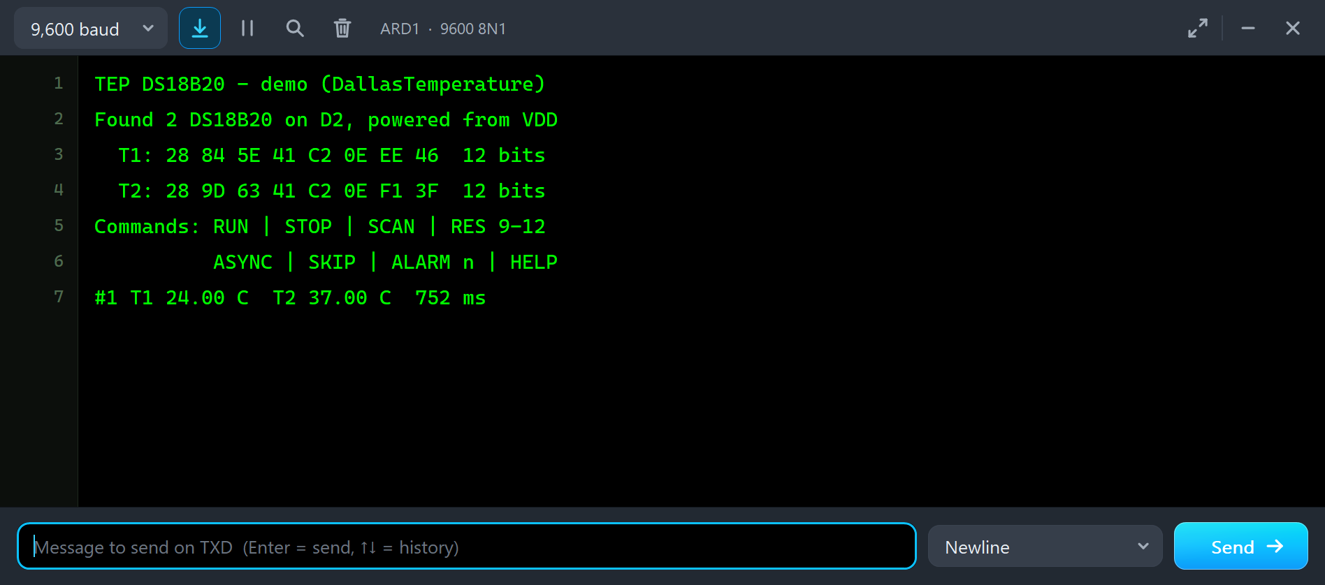
Both UNOs have the serial monitor built in, and it opens at Run. The screenshots use its Simple interface. Node 1 starts like this:
TEP DS18B20 - demo (DallasTemperature)
Found 2 DS18B20 on D2, powered from VDD
  T1: 28 84 5E 41 C2 0E EE 46  12 bits
  T2: 28 9D 63 41 C2 0E F1 3F  12 bits
Commands: RUN | STOP | SCAN | RES 9-12
          ASYNC | SKIP | ALARM n | HELP
#1 T1 24.00 C  T2 37.00 C  752 ms
The search found both sensors on D2 and printed their 8-byte ROM codes: the family 28, the 48-bit serial and the CRC. Every reading prints both temperatures and the time the conversion took, 752 ms at 12 bits. Node 2 finds its two sensors in the same way and knows that they run on parasite power:
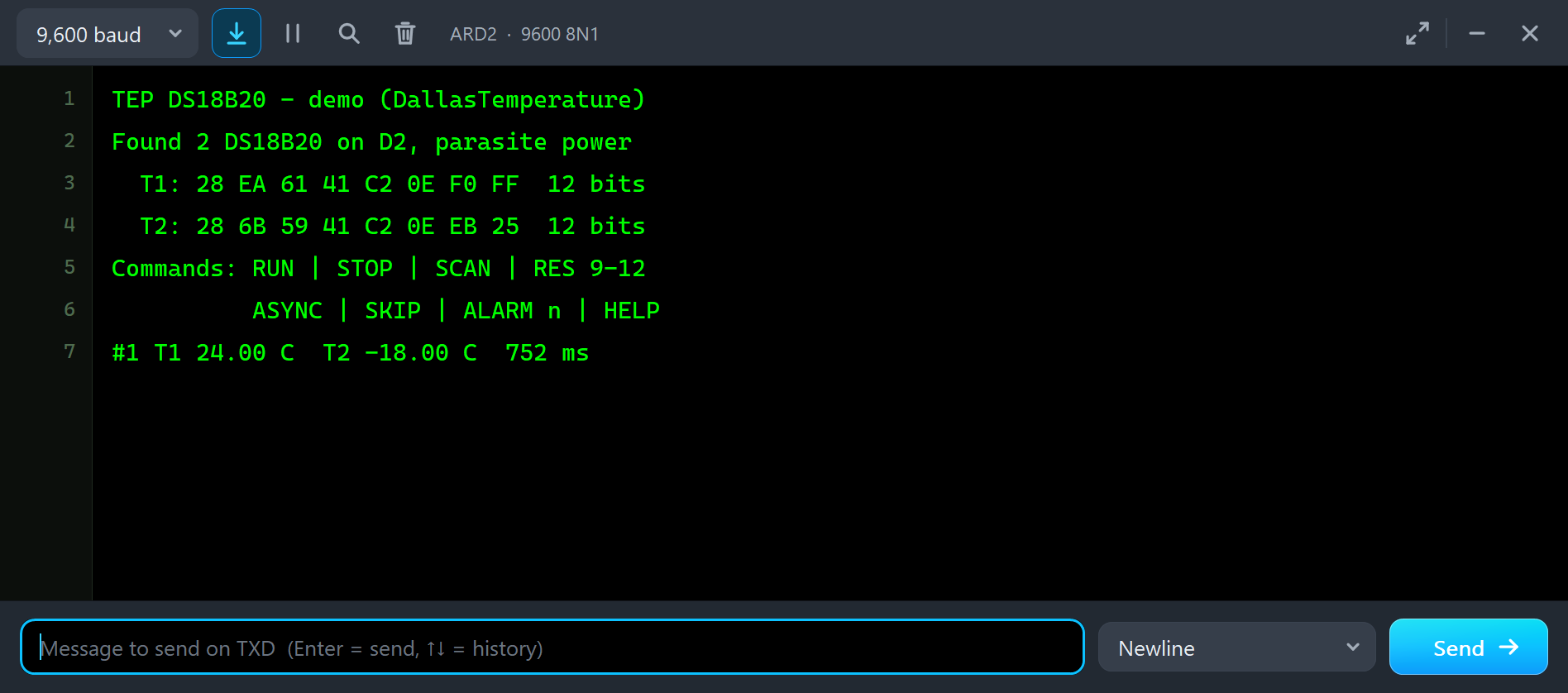
Found 2 DS18B20 on D2, parasite power
  T1: 28 EA 61 41 C2 0E F0 FF  12 bits
  T2: 28 6B 59 41 C2 0E EB 25  12 bits
Type a command in the monitor and press Enter: STOP stops the readings, RUN starts them again, SCAN searches the wire again, and RES, ASYNC, SKIP and ALARM are explained below. HELP lists them all.
The Advance Pop-Up Window
At Run, each Advance device opens its own window, named after its part, for example DS18B20 (TO-92), with the look of our TEP Serial Monitor Advance for Proteus. It has three tabs, Sensor, Event log and Tests, plus Settings and Help behind the gear and question mark icons. The status bar at the bottom always shows the temperature, what the sketch reads, the conversions and the power.
The Sensor Page
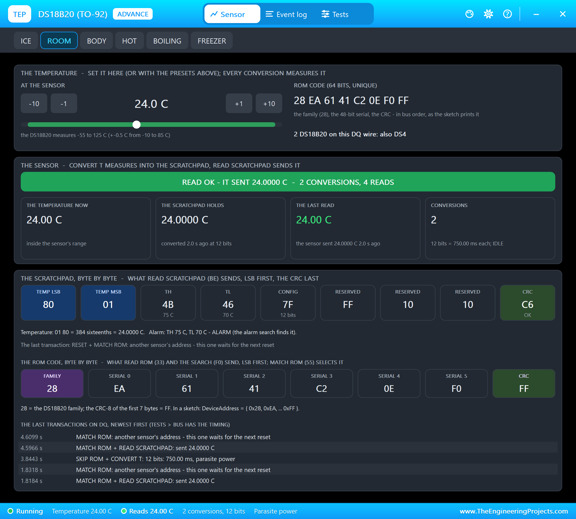
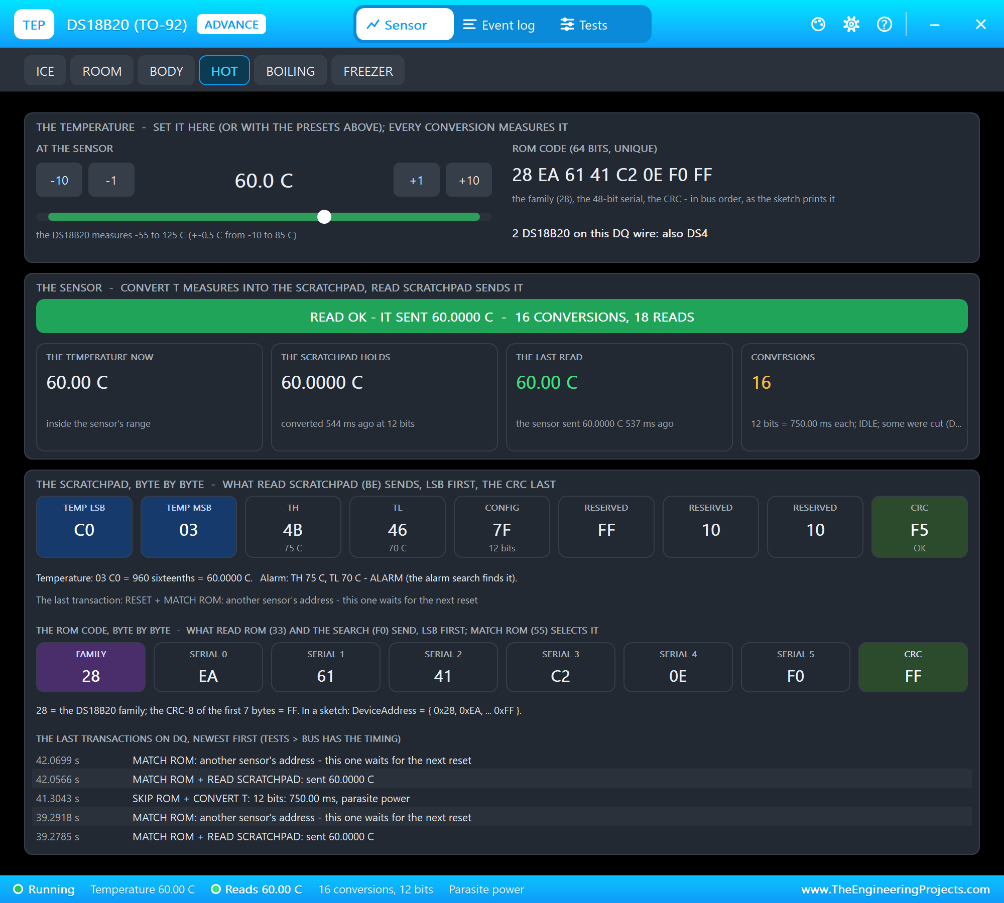
The top card is the temperature: the presets sit on the toolbar, and under the card's title are -10, -1, +1 and +10 C with a scale that shows the DS18B20's range in green. Next to it are the ROM code, in the order the sketch prints it, and the other sensors on the same wire. The middle card is the sensor: the banner, the temperature now, what the scratchpad holds from the last conversion, the last read with the value DallasTemperature makes of it, and the conversions.
The bottom card shows the scratchpad byte by byte: the temperature LSB and MSB, TH, TL, the configuration byte with the resolution, the reserved bytes and the CRC, with the temperature worked out: 01 80 is 384 sixteenths, so 24.0000 C. Under it are the 8 bytes of the ROM code and the last transactions on DQ, each one a reset, a ROM command and a function command, for example "MATCH ROM + READ SCRATCHPAD: sent 24.0000 C".
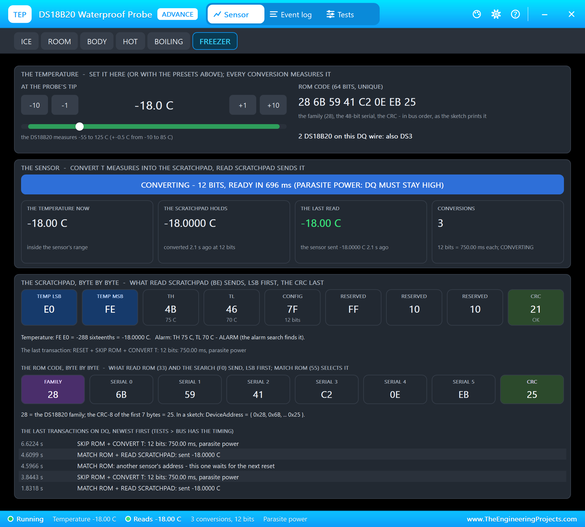
Negative temperatures are two's complement. The probe of node 2 sits at -18 C, and its scratchpad starts with E0 FE: FEE0 in hexadecimal is -288, and -288 sixteenths are -18.0000 C.
The Event Log
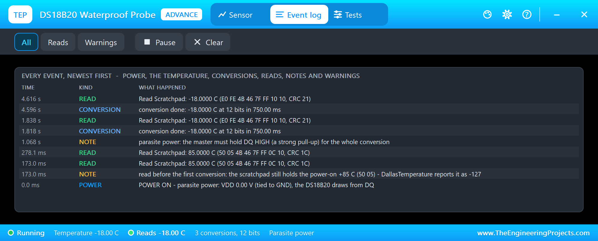
The Event log lists everything that happened, newest first. At 0.0 ms the probe of node 2 gets its power: "POWER ON - parasite power: VDD 0.00 V (tied to GND), the DS18B20 draws from DQ". During begin() DallasTemperature reads the scratchpad before any conversion, and the log notes that it still holds the power-on +85 C, which DallasTemperature reports as -127. Then come the conversions and the reads. Filter the log by reads or warnings, pause it, or clear it.
Change the Temperature
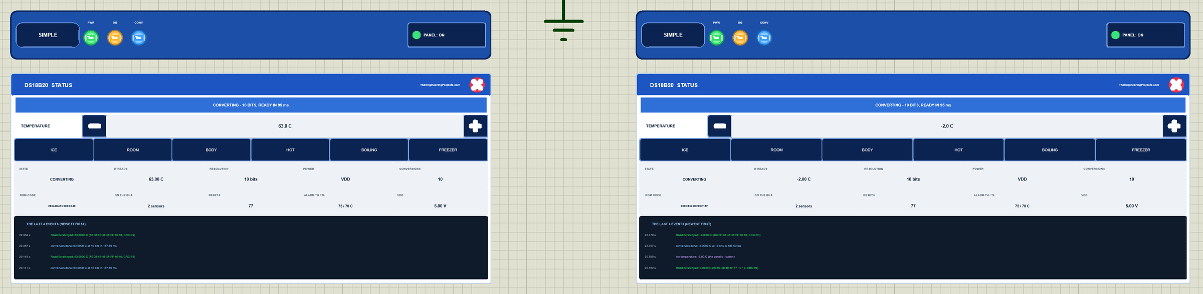
Now let's change the temperature while the simulation runs. On node 1 we clicked HOT on the TO-92's panel and ICE on the probe's panel, with the mouse:
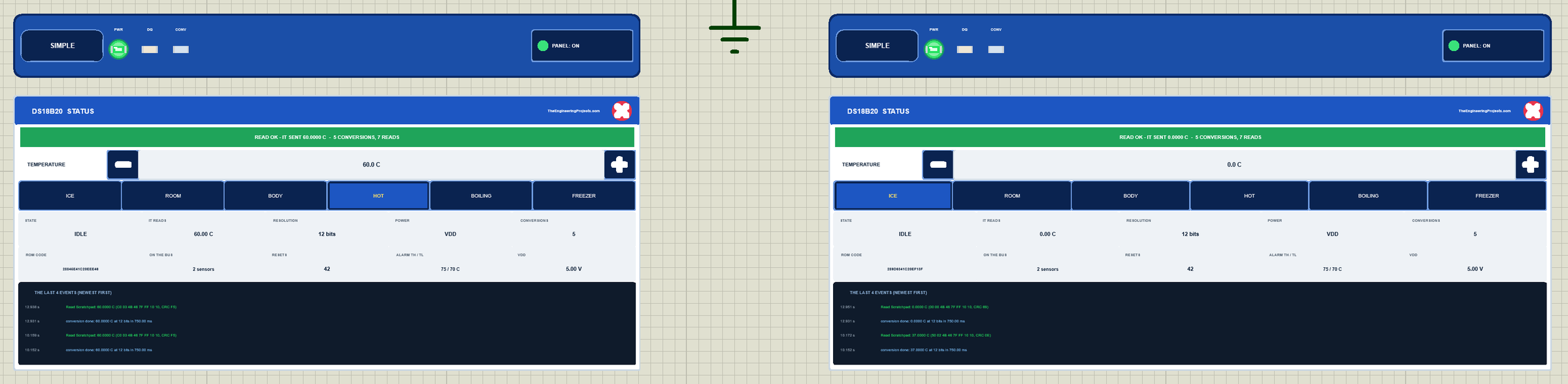
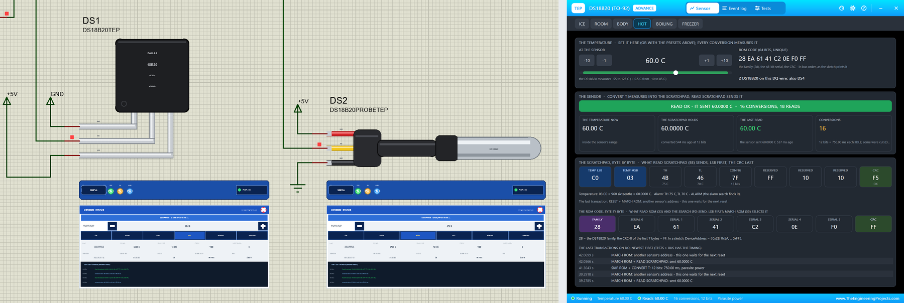
The next reading shows the new values, because DallasTemperature starts a fresh conversion every time. The pop-up works the same way: HOT in DS3's pop-up, and the next readings on node 2 say 60.00 C.
Classic DS18B20 Mistakes, Simulated
The demo sketch can make the most common DS18B20 mistakes on purpose, so you can see what they look like before they happen on your desk. All of them were run in the final test.
Reading Without Waiting
setWaitForConversion(false) makes requestTemperatures() return at once, which is great for a busy sketch, as long as you wait the conversion time before you read. We stopped the readings, clicked HOT on DS1 and typed ASYNC:
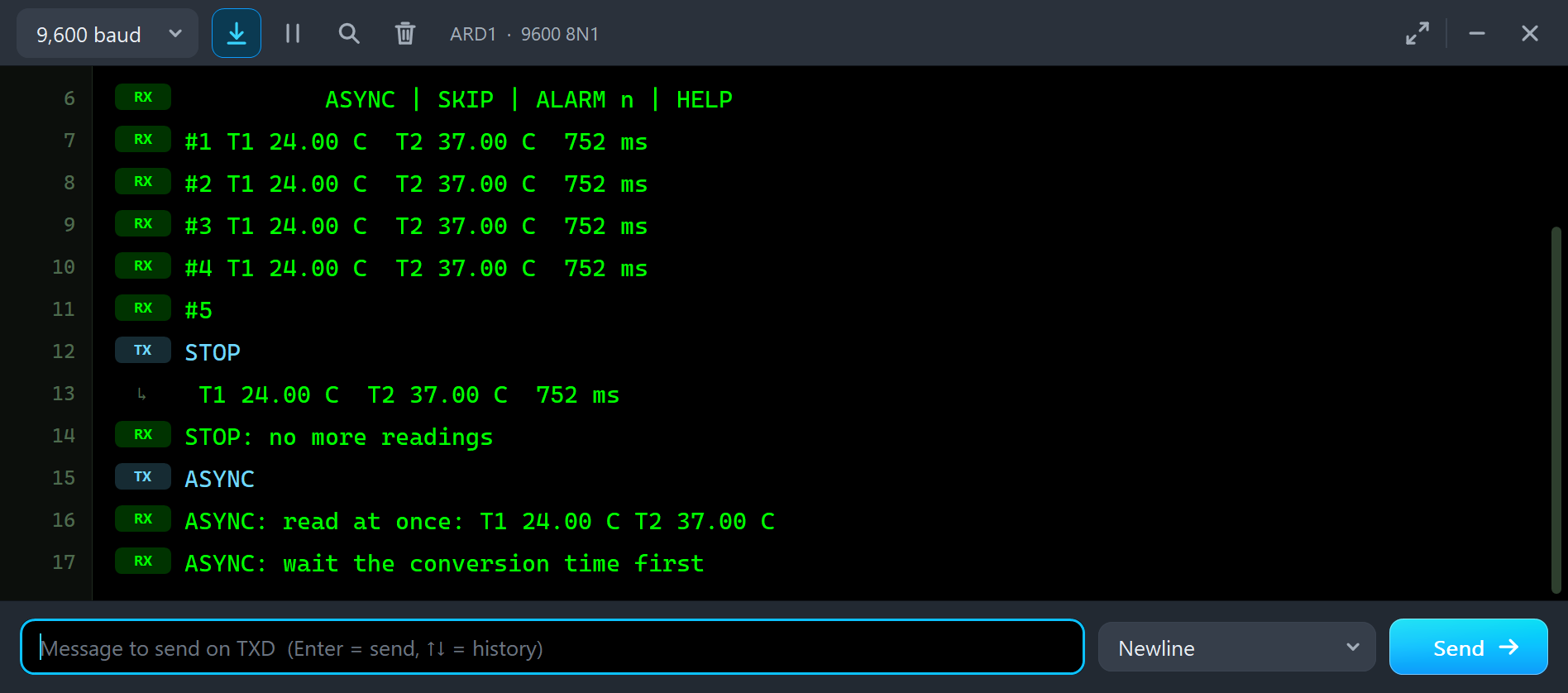
STOP: no more readings
ASYNC
ASYNC: read at once: T1 24.00 C T2 37.00 C
ASYNC: wait the conversion time first
T1 still says 24.00 C, although the sensor is at 60 C. The read came while the new conversion was running, so the scratchpad still held the old result. After RUN the normal readings, which wait, show 60.00 C. The very first time, before any conversion, the same mistake gives the power-on 85 C, and DallasTemperature turns that into -127.
Reading Without Waiting on Parasite Power
On parasite power the same mistake is worse. Here is ASYNC on node 2:
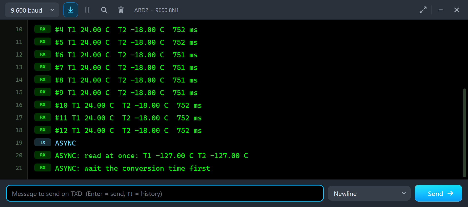
ASYNC
ASYNC: read at once: T1 -127.00 C T2 -127.00 C
ASYNC: wait the conversion time first
Both sensors give -127.00 C, DallasTemperature's value for an error. The read starts with a reset, and a reset pulls DQ LOW for 480 us. On parasite power DQ is the sensors' only supply during the conversion, so they lose their power and start again with the power-on +85 C, which DallasTemperature reports as -127. The pop-up of DS3 shows it all:
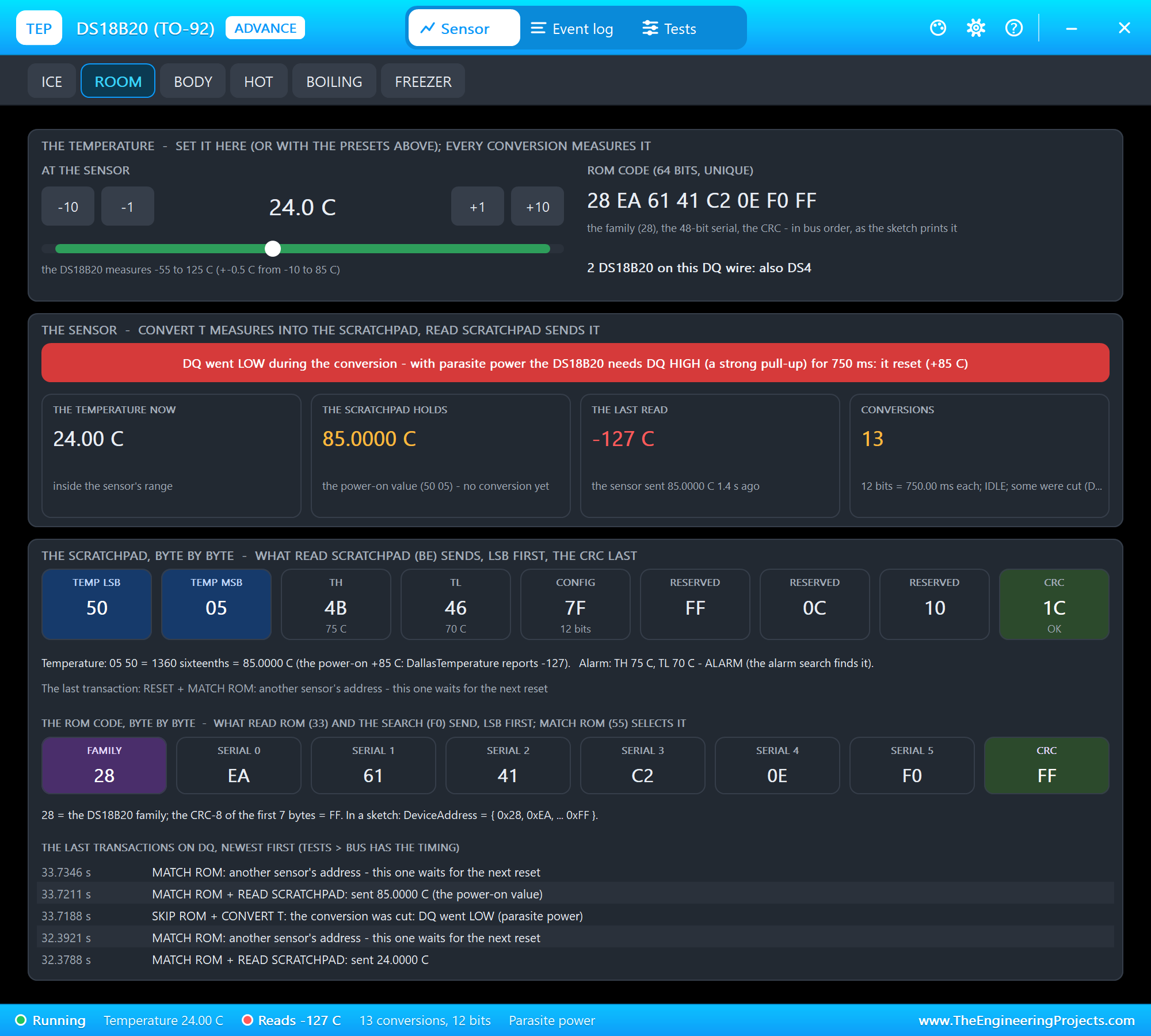
The banner says "DQ went LOW during the conversion - with parasite power the DS18B20 needs DQ HIGH (a strong pull-up) for 750 ms: it reset (+85 C)". The scratchpad is back at 50 05 with the reserved byte 0C, the power-on pattern, and the last transactions show the cut conversion and the read that followed. The Power tool counts it:
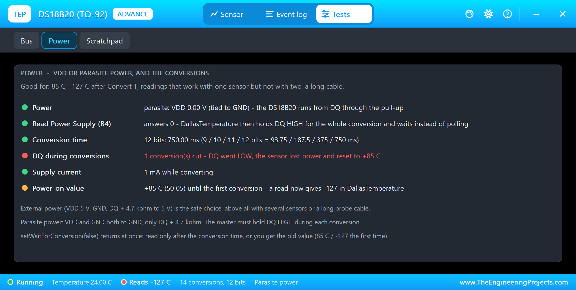
The Power tool is the one to open for 85 C or -127 C after a conversion. It shows VDD or parasite power, what READ POWER SUPPLY answers and what DallasTemperature does with it (on parasite power it holds DQ HIGH and waits instead of asking), the conversion time for the resolution, the conversions cut by DQ going LOW, the supply current and whether the power-on value is still in the scratchpad.
Resolution, Skip ROM and the Alarm Search
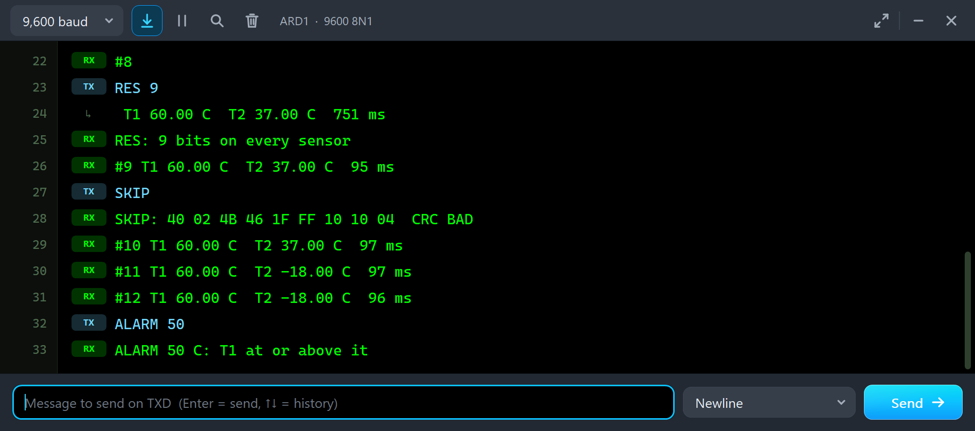
RES 9
RES: 9 bits on every sensor
#9 T1 60.00 C  T2 37.00 C  95 ms
SKIP
SKIP: 40 02 4B 46 1F FF 10 10 04  CRC BAD
#10 T1 60.00 C  T2 37.00 C  97 ms
#11 T1 60.00 C  T2 -18.00 C  97 ms
#12 T1 60.00 C  T2 -18.00 C  96 ms
ALARM 50
ALARM 50 C: T1 at or above it
RES 9 writes 9 bits into both sensors, and the next reading takes 95 ms instead of 752: the conversion time follows the resolution, 93.75 ms at 9 bits. The steps are 0.5 C then, so 9 bits suit a fast sketch and 12 bits a precise one.
SKIP reads the scratchpad after SKIP ROM. With two sensors on the wire both answer at the same time, and the open-drain wire ANDs their bits: DS1 sent C0 03 for 60 C, DS2 sent 50 02 for 37 C, and the Arduino received 40 02, which is neither. The CRC does not match, so DallasTemperature would say -127. Both STATUS panels say so in red:
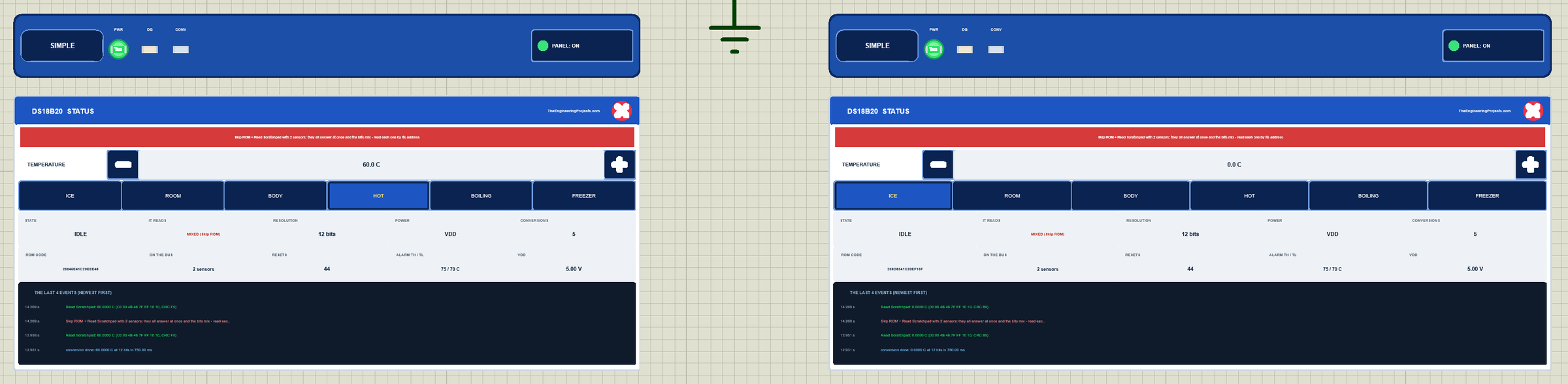
Then we clicked FREEZER on DS2, and the readings followed: -18.00 C. ALARM 50 sets the high limit TH to 50 C on both sensors, converts, and runs the alarm search (EC), in which only sensors with an alarm take part: it found T1 at 60 C and not T2 at -18 C.
The Bus and the Scratchpad Tools
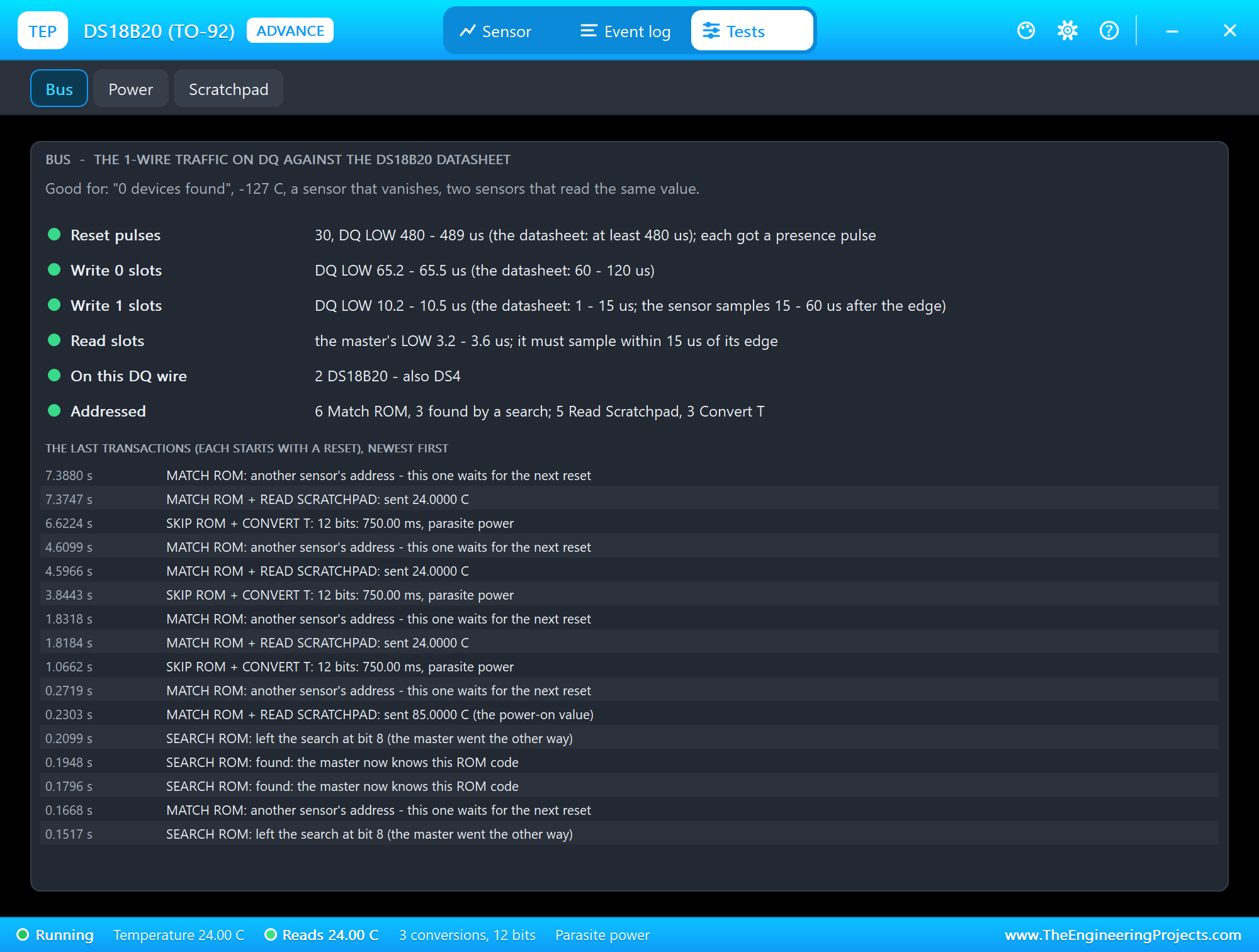
The Bus tool is the one to open for "0 devices found" or a sensor that vanishes. It measures the Arduino's timing against the datasheet: the reset pulses (480 us), the write-0 slots (60 to 120 us), the write-1 slots (1 to 15 us) and the read slots; it lists the sensors on the wire, what was addressed, the Skip ROM and pull-up warnings, and the last transactions, each with its ROM command, its function command and what came of it.
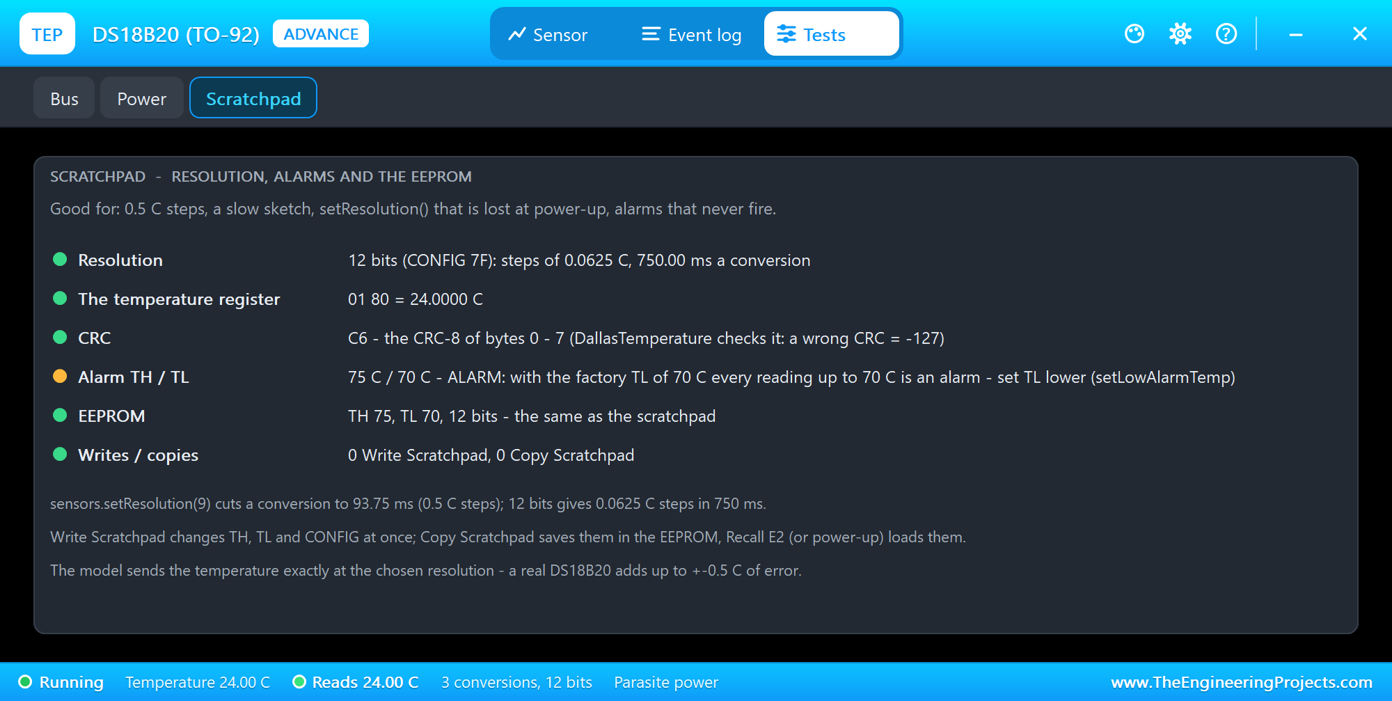
The Scratchpad tool shows the resolution with its steps and conversion time, the temperature register, the CRC, the alarm limits TH and TL, and the EEPROM. Watch the alarm row: a new DS18B20 comes with TH 75 C and TL 70 C, so every temperature up to 70 C is an alarm until you set TL lower.
The Simulation Log
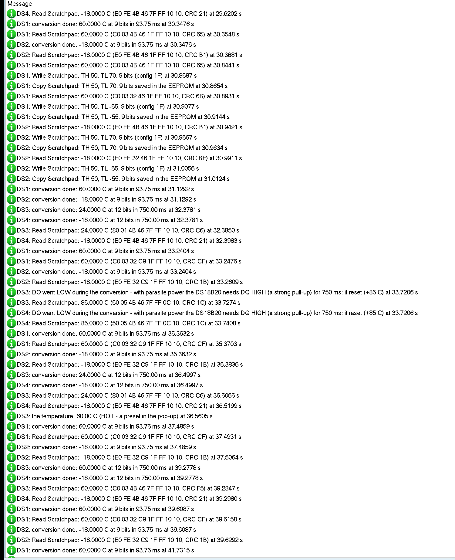
Every sensor also writes to the simulation log of Proteus, with the exact simulation time. This part shows the parasite mistake and the HOT preset on node 2:
DS3: DQ went LOW during the conversion - with parasite power the DS18B20 needs DQ HIGH (a strong pull-up)
     for 750 ms: it reset (+85 C) at 33.7206 s
DS3: Read Scratchpad: 85.0000 C (50 05 4B 46 7F FF 0C 10, CRC 1C) at 33.7274 s
DS3: the temperature: 60.00 C (HOT - a preset in the pop-up) at 36.5605 s
DS3: conversion done: 60.0000 C at 12 bits in 750.00 ms at 39.2778 s
DS3: Read Scratchpad: 60.0000 C (C0 03 4B 46 7F FF 10 10, CRC F5) at 39.2847 s
The reset of the early read cut the conversion, the next read sent the power-on 85 C, and after HOT the next conversion and read show 60 C with the scratchpad C0 03.
How the Model Works
Proteus runs the Arduino's writes to DQ as digital events, each with its exact time. The model watches the DQ line: a LOW of 480 us is a reset, and every shorter falling edge starts a time slot. In a write slot the model samples DQ 30 us after the edge, the way the chip does; in a read slot it pulls DQ LOW for a 0 and lets go at the right time. Its presence pulses and its 0s are driven from simulator callbacks at their exact times, and DQ is open drain like the real pin: LOW or released, with the 4.7 kohm on the schematic doing the pulling up.
Each part knows the other DS18B20s on its wire, so two sensors that answer at once really mix their bits on the wire, and the search really walks the ROM codes. The temperature comes from the value you set, quantized to the resolution, and the sensor's VDD and GND are real analog pins: VDD below 1.5 V means parasite power, below 3.0 V the sensor is off.
Troubleshooting
- "Found 0" or -127 everywhere: no 4.7 kohm pull-up on DQ (the panel says DQ floats), the wrong pin in
OneWire oneWire(pin), or no power. - 85.00 C: a read before the first conversion; DallasTemperature 4 turns it into -127. Call
requestTemperatures()first. - -127 now and then on parasite power: the sketch talks on DQ during a conversion. Wait the conversion time.
- -127 with several sensors: SKIP ROM and READ SCRATCHPAD in your own code. Read each sensor by its address.
- The value lags:
setWaitForConversion(false)reads the last conversion. - Steps of 0.5 C and fast readings: the resolution is 9 bits;
setResolution(12)gives 0.0625 C steps in 750 ms. - No part, no answer at all or no monitor: TEPDS18B20.DLL or TEPARDUINO.DLL is missing from MODELS and the project folder; a closed monitor opens again with a click on the UNO's USB port.
Things to Know Before Using a Real DS18B20
- The pull-up: one 4.7 kohm from DQ to VDD for the whole wire; for long cables or many sensors 2.2 to 3.3 kohm.
- Parasite power: fine for a few sensors on short wires; above about 100 C or with long cables, use VDD.
- Long probes: run the cable in a line from sensor to sensor, not as a star, and keep VDD power.
- Response time: a probe in water follows a change in seconds, in air much slower; the model follows at once.
- Clones: many cheap probes carry clone chips; the code is the same, but some details, like the power-on value, can differ.
Limitations of the Simulation
- Not modelled: the sensor's accuracy and noise (the model sends the temperature exactly at the chosen resolution), its slow response to a change, self-heating, the strong pull-up's current in parasite mode, long-cable effects and the quirks of clone chips.
- In Proteus, polling a conversion, DallasTemperature's default with VDD power, now and then ends early: about 1 read slot in 50,000 comes back as a 1 to the Arduino although the sensor holds DQ LOW, a timing effect of Proteus on the pull-up's analog node, and that reading shows the last value. The demo waits the conversion time instead, with
setCheckForConversion(false). - The strips, their LEDs and the panels are TEP additions.
- The model is our own, written from the DS18B20 datasheet. This library is not made or endorsed by Maxim, Analog Devices, the authors of OneWire or DallasTemperature, the makers of these probes or Labcenter.
- Licences: the demo sketch uses OneWire 2.3.8 and DallasTemperature 4.0.6 (both MIT), which are not shipped; install them from the Library Manager. The demo's HEX file contains them and the Arduino AVR core 1.8.6 with LGPL-licensed code; the licence texts and the source links are in the README.
- Tested in Proteus 8.5 in October 2026 (the demo as shipped on two Arduino UNO V4.0 boards with their built-in monitors: the search and the readings on both nodes, the presets and the - / + buttons with the mouse, ASYNC on both nodes, RES 9, SKIP, ALARM 50, the red X and PANEL, the pop-ups and the three tools; 43.6 s of simulation took 132 s, about 0.3 x real time with both pop-ups and both monitors open). Proteus 7 is not supported.
So, that was all about the DS18B20 Library for Proteus V1.0. I hope the 1-Wire slots, the ROM codes, the scratchpad and parasite power are clear now, so your thermometer reads the right temperature from the first run, even with several sensors on one wire. If you use the DS18B20 Library for Proteus in a project, please share it in the comments or in our forum, and if you have any questions, ask in the comments and I will help you out. Till the next tutorial, take care and have fun!