Hello friends, I hope you all are doing great. Today, I am going to share the new DS3231 RTC Module Library for Proteus V1.0. The DS3231 is the real-time clock of almost every Arduino clock, data logger, timer and alarm project: a small blue board with a coin cell that keeps the time and the date even while the Arduino is off. The Arduino reads the time over I2C whenever it needs it, sets alarms that pull a pin LOW at a given second, and stores data in the EEPROM chip next to the clock. Until now there was no DS3231 module to try all that in Proteus.
Behind the parts sits our own model, written from the DS3231 and AT24C32 datasheets. The clock counts in BCD in the same registers as the real chip, a fresh module starts at 2000-01-01 with OSF set, the two alarms pull INT / SQW LOW at their exact simulation time, the pin can give a 1 Hz square wave, the temperature is converted every 64 s, the coin cell keeps the time when VCC goes, and the AT24C32 keeps 4 KB of your data. The unmodified RTClib drives it on the Arduino. You get a Simple device with a live STATUS panel and an Advance device with a pop-up window that shows the clock, every register and every I2C transaction. The demo runs on our Arduino UNO V4.0.
NOTICE: a real-time clock is easy to fake: a part that answers the PC's time whenever it is asked. We wanted more. Our module keeps its own time from the moment the simulation starts, latches the seven time registers at the start of a read as the real chip does, refuses alarms RTClib would refuse, loses everything when both VCC and the coin cell are gone, and the EEPROM does not answer while it writes. It took our team a lot of hard work. Your feedback is the fuel that keeps us going, so please tell us what you think in the comments below or in the DS3231 RTC Module board of our forum. And if our free libraries help you, you can buy us a coffee. So, let's get started with the DS3231 RTC Module Library for Proteus V1.0:
What is the DS3231 RTC Module?
The DS3231 is a real-time clock chip with its 32.768 kHz crystal inside the package and a temperature sensor that corrects the crystal's drift: it keeps +-2 ppm from 0 to 40 C, about a minute a year. The common module, the ZS-042, puts it on a blue board together with an AT24C32 EEPROM (4 KB), the pull-up resistors of the I2C bus and a holder for a CR2032 coin cell on the back. Both chips share the I2C bus: the clock answers at 0x68, the EEPROM at 0x57.
| ZS-042 DS3231 module | |
|---|---|
| Supply | 2.3 V - 5.5 V on VCC (5 V from the Arduino) |
| Clock | seconds to year, 2000 - 2199, leap years, 12- or 24-hour mode, the day of the week |
| Accuracy | +-2 ppm from 0 to 40 C (a temperature-compensated oscillator inside the chip) |
| Interface | I2C: the DS3231 at 0x68, the AT24C32 at 0x57 (A0 - A2 pads on the board) |
| Alarms | alarm 1 (seconds, minutes, hours, day / date) and alarm 2 (minutes, hours, day / date) |
| INT / SQW | open drain: the alarm interrupt, or a square wave of 1 Hz, 1.024, 4.096 or 8.192 kHz |
| Temperature | in 0.25 C steps, converted every 64 s |
| Backup | a CR2032 / LIR2032 coin cell keeps the clock running without VCC |
| Arduino library | RTClib by Adafruit (2.1.4 in the demo) |
The Registers and BCD
The DS3231 has 19 registers, 00 to 12. The first seven hold the time in BCD - each byte two decimal digits, so 45 seconds is the byte 0x45. The sketch writes the time once, and from then on reads it whenever it needs it: it sets the register pointer to 00 and reads seven bytes. The chip copies the time into a buffer at the start of the read, so a second that rolls over in the middle of the read cannot give 12:59:00 instead of 13:00:00.
| Register | Holds |
|---|---|
| 00 - 06 | seconds, minutes, hours (bit 6: 12-hour mode), day 1 - 7, date, month (bit 7: the century), year |
| 07 - 0A | alarm 1: seconds, minutes, hours, day / date - bit 7 of each is its mask bit |
| 0B - 0D | alarm 2: minutes, hours, day / date (no seconds: it matches at 00 s) |
| 0E | control: EOSC, BBSQW, CONV, RS2, RS1, INTCN, A2IE, A1IE |
| 0F | status: OSF, EN32kHz, BSY, A2F, A1F |
| 10 | the aging offset |
| 11 / 12 | the temperature: the whole degrees, then the quarters in bits 7 - 6 |
Alarms and INT / SQW
An alarm matches when every field whose mask bit is 0 equals the time. With all masks set, alarm 1 fires every second; with only the day masked, it fires every day at the same time. A match sets the alarm's flag, A1F or A2F, and if INTCN is 1 and the alarm's interrupt is enabled, the INT / SQW pin goes LOW and stays LOW until the sketch writes the flag back to 0. With INTCN 0 the same pin gives a square wave instead - then the alarms only set their flags.
OSF and the Coin Cell
The coin cell keeps the oscillator running when VCC goes. When both are gone, the chip stops; at the next power-up the registers are cleared to 2000-01-01 00:00:00 and the oscillator stop flag, OSF, is set. That is what RTClib's lostPower() reads: a sketch checks it at the start and sets the time once with adjust(), which clears OSF again.
What's New in DS3231 RTC Module Library for Proteus V1.0
- The DS3231's registers: the time and date in BCD, 12- and 24-hour mode, the century, the day register, the time latched at the start of a read, writing the seconds restarting the second.
- Two alarms with their mask bits - every second or minute, at given seconds, minutes or hours, on a date or a day of the week - with their flags and the INT / SQW pin LOW at the exact time.
- The square wave: 1 Hz, 1.024, 4.096 or 8.192 kHz on SQW; the 32 kHz output on 32K.
- The temperature in 0.25 C steps, converted every 64 s: change the air and the chip shows it after its next conversion.
- Power as on the bench: VCC off with the coin cell in - the clock keeps running; both gone - everything lost, 2000-01-01 and OSF; EOSC stopping the oscillator on the cell.
- A clickable coin cell: click it while the simulation runs to take it out, once more to put it back.
- The AT24C32 EEPROM: 4096 bytes, 32-byte pages that wrap, 5 ms to write with no ACK meanwhile, sequential reads.
- Every I2C transaction decoded in the Advance pop-up: the time read, the register written, the EEPROM access.
- Four test tools on the Advance device: Time, Alarms, EEPROM and Power.
- A two-node demo on our Arduino UNO V4.0 with RTClib: one new module that sets its time from the sketch, one that kept the PC's time; alarms, the square wave, the temperature and the EEPROM from the serial monitor.
- A compact package: about 1.28 MB, without the C++ source code of the model.
Two Devices: Simple and Advance
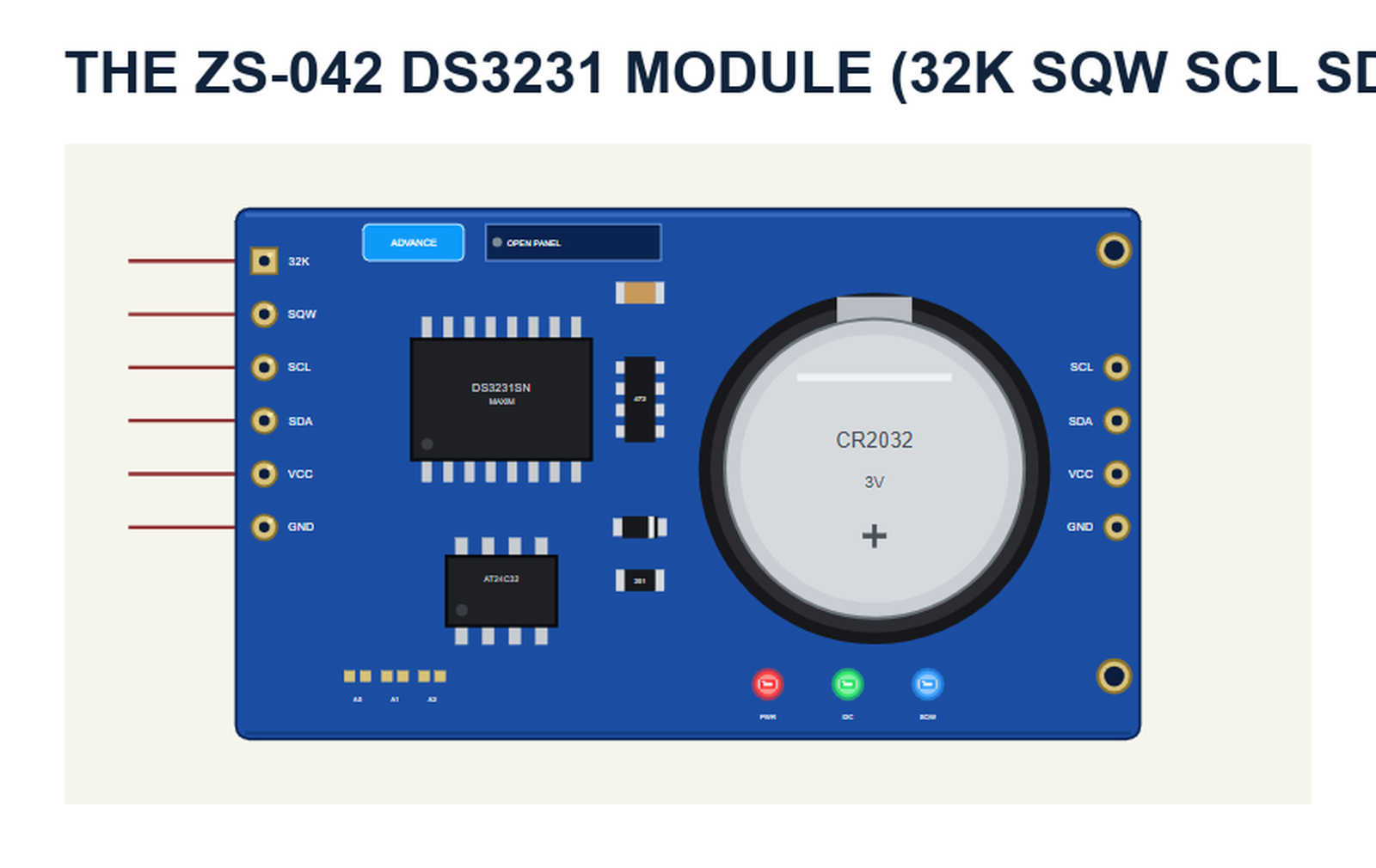
The part is the ZS-042 seen from above, drawn at about its real size next to the Arduino UNO: the DS3231SN in its SOIC-16, the AT24C32 with its three address pads, the 472 resistor network (the 4.7 kohm pull-ups of SCL, SDA, SQW and 32K), the charging diode with its 201 resistor, the 6-pin header 32K SQW SCL SDA VCC GND on the left and the 4-pin pass-through header on the right. The coin cell sits under a real board; we drew it beside the chips so you can click it. The SIMPLE / ADVANCE badge, the PWR, I2C and SQW LEDs and the panel button are TEP additions: PWR lights with VCC, I2C with every access, SQW while the pin is LOW.
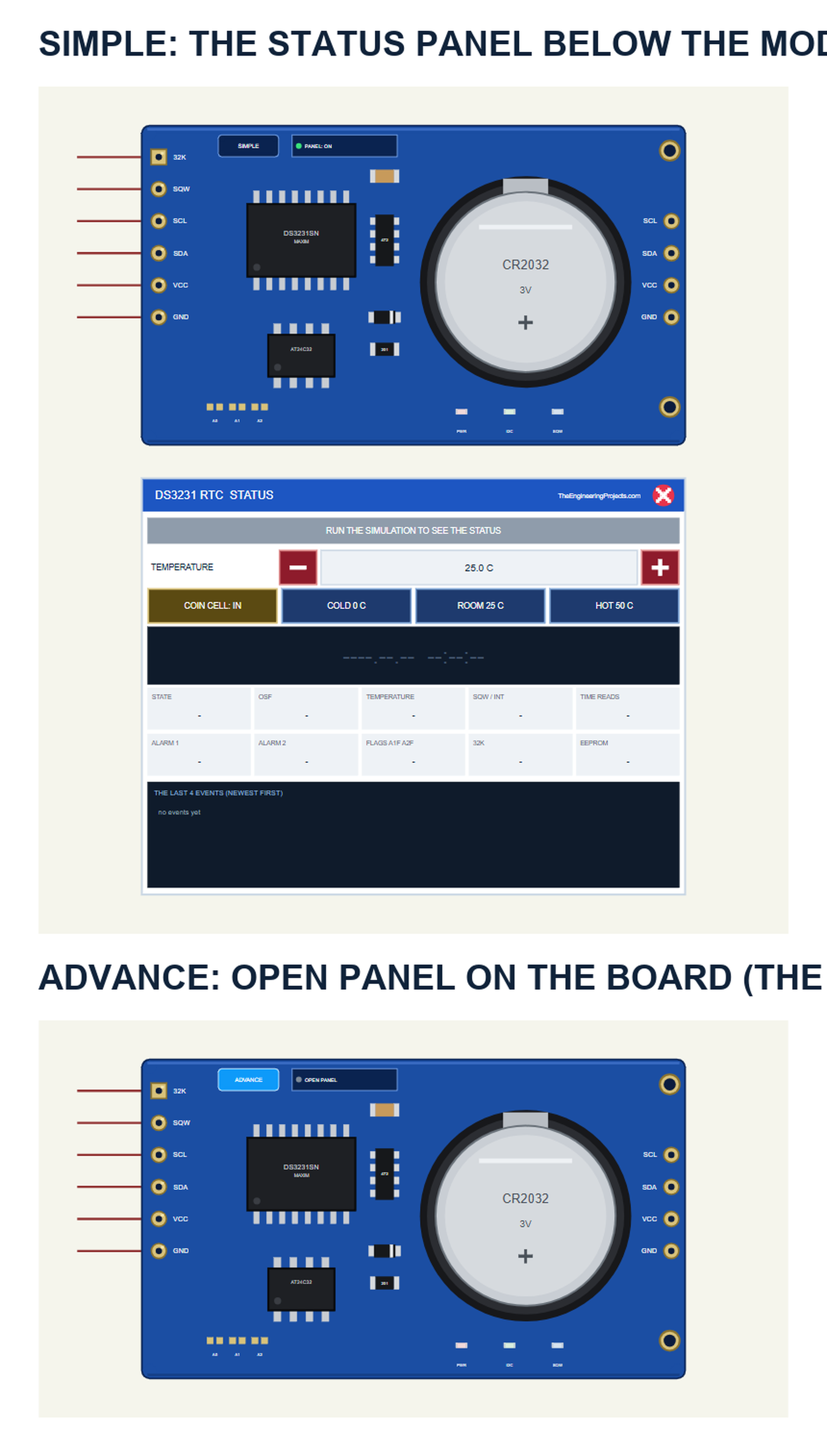
| Simple | Advance | |
|---|---|---|
| Device | DS3231TEP | DS3231ADVTEP |
| On the schematic | The module and the STATUS panel | The module |
| The coin cell | Click it on the module, or COIN CELL on the panel | Click it on the module, or COIN CELL in the pop-up |
| The temperature | TEMPERATURE - / + and COLD, ROOM, HOT on the panel | The same on the pop-up's toolbar |
| Status | Banner, the clock, 10 readouts, the last 4 events | A pop-up: Clock, Event log, Tests |
Download DS3231 RTC Module Library for Proteus
Click the button below to download DS3231-RTC-Module-Library-for-Proteus-v1.0.zip (about 1.28 MB, without the C++ source code of the model):
DS3231 RTC Module Library for Proteus V1.0- README.txt: the devices, installation, the demo, wiring, the test tools, the properties and real hardware.
- Proteus Library Files:
TEPDS3231.LIBandArduinoV4TEP.LIBfrom our Arduino Library for Proteus V4.0. - Proteus Model Files:
TEPDS3231.DLLandTEPARDUINO.DLL. - Proteus Simulation:
DS3231-RTC-ArduinoUnoV4.pdsprj,DS3231_Demo.hexand copies of the two DLLs. - Arduino Code:
DS3231_Demo.ino- it needs the RTClib library (not included; install it with the Library Manager, it brings Adafruit BusIO with it).
No Proteus yet? Read How to Download and Install Proteus 7 and 8. New to libraries? Follow How to Install a New Library in Proteus.
How to Install DS3231 RTC Module Library for Proteus
- Close Proteus and extract the whole zip file, for example to your Desktop.
- Copy the two files from Proteus Library Files into the LIBRARY folder of Proteus (usually
C:\Program Files (x86)\Labcenter Electronics\Proteus 8 Professional\LIBRARY). - Copy
TEPDS3231.DLLandTEPARDUINO.DLLfrom Proteus Model Files into the MODELS folder. - Delete
TEPDS3231.IDXfrom the LIBRARY folder if it is there. - Start Proteus, press P and search for DS3231.
Tip: keep the Proteus Simulation folder together, because the project needs its .hex file and the DLLs beside it. The library is tested in Proteus 8.5; Proteus 7 is not supported.
The DS3231 Part in Proteus
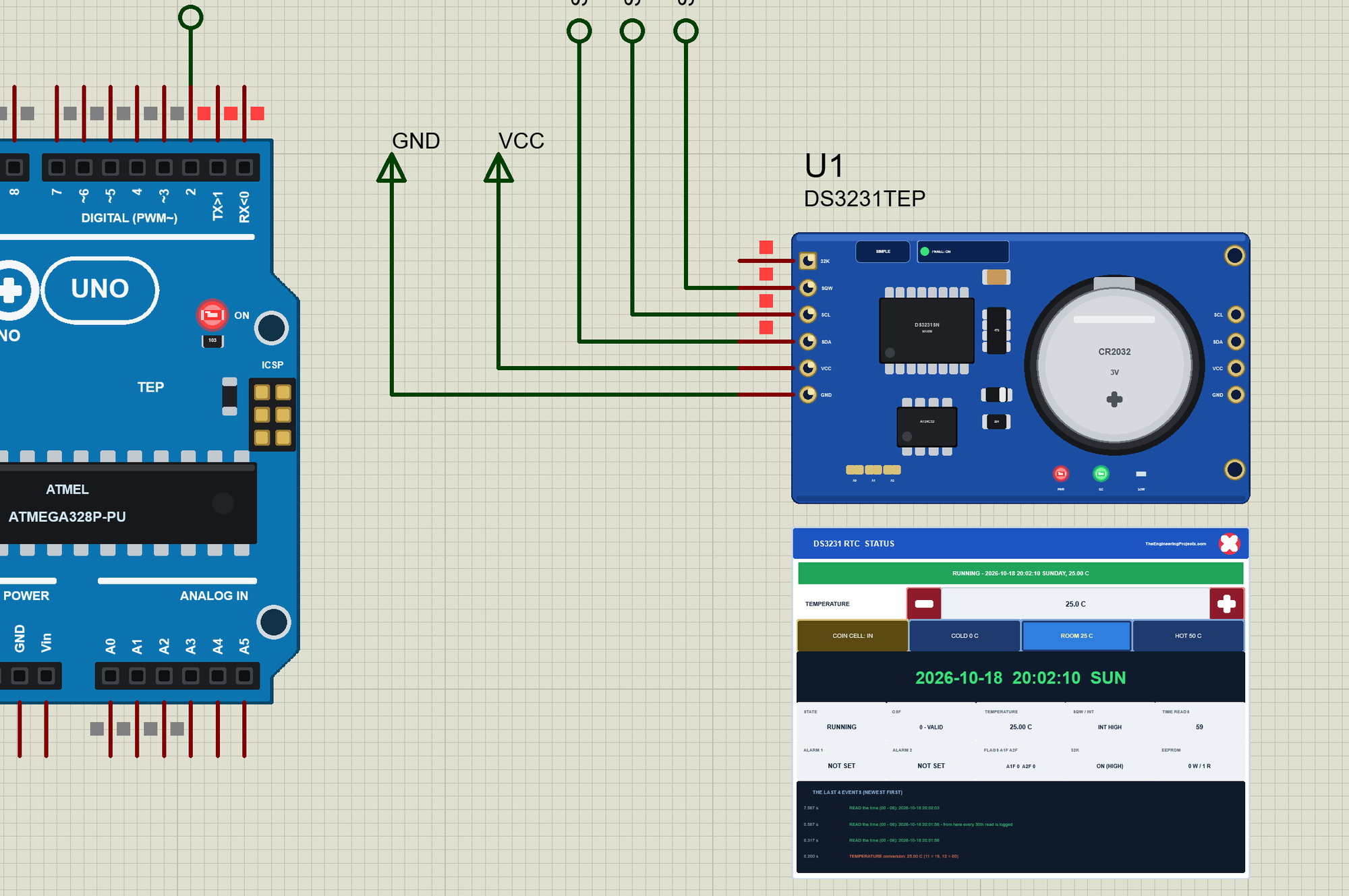
The Simple device adds the STATUS panel below the module. Its banner says what the module is doing: green while it runs, blue for a moment when the sketch sets the time, amber for OSF, an alarm, a missing coin cell or VCC off, red when it has no power at all. Below it are the temperature with its - and + buttons, the actions COIN CELL, COLD 0 C, ROOM 25 C and HOT 50 C, the clock as the chip counts it, ten readouts and the last four events.
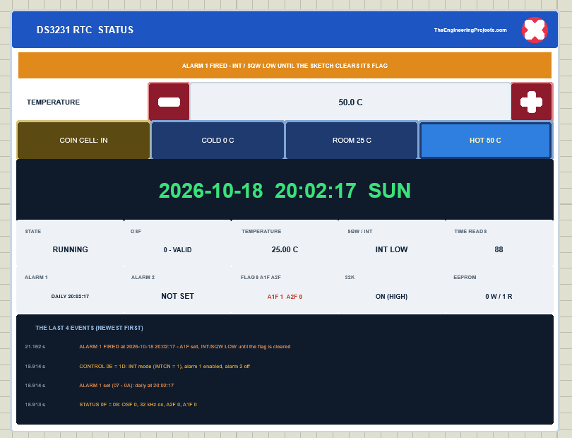
The readouts are the state, OSF, the chip's temperature, the INT / SQW pin, the time reads, alarm 1 and alarm 2 in a few words, the flags A1F and A2F, the 32K output and the EEPROM's writes and reads. The red X closes the STATUS panel, and the PANEL button on the board opens it again. The Advance device keeps the schematic clean - only the module; the live data opens in a pop-up window at Run, and the OPEN PANEL button on the board brings the window back:
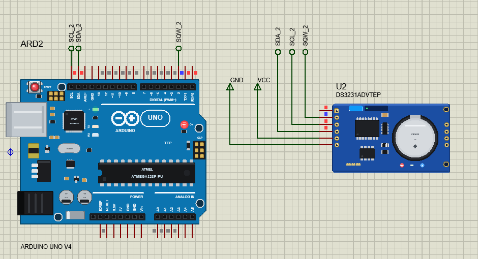
The properties set the start: TIME - PC (the PC's clock at Run, as if the coin cell had kept it), LOST (2000-01-01 with OSF set, a new module) or a time of your own -, BATTERY (the coin cell IN or OUT), TEMPERATURE, OUT32K and, on the Simple device, PANEL. Every run starts again from the properties.
The Demo Circuit
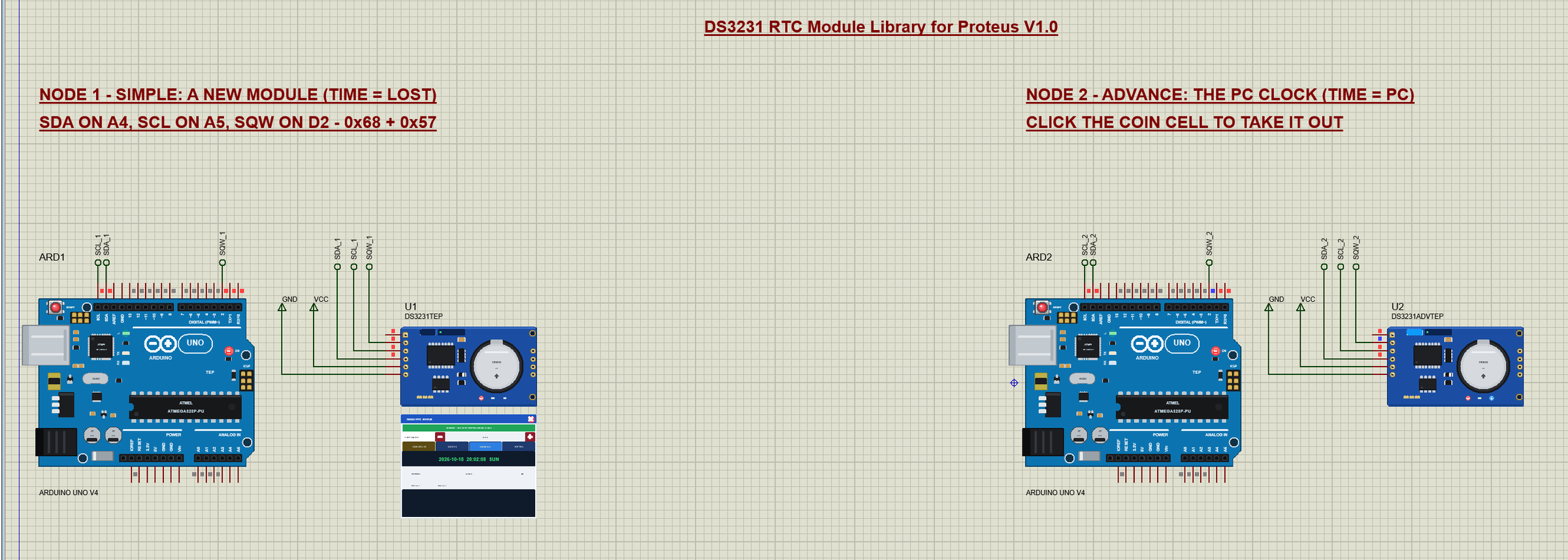
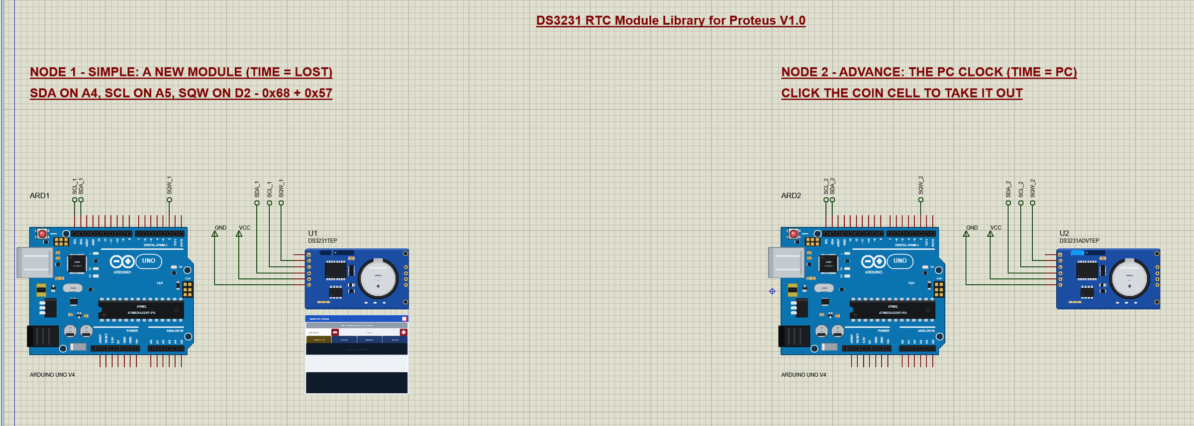
The demo project has two nodes, each an Arduino UNO V4.0 from our Arduino UNO Library for Proteus V4.0 with a ZS-042 module. Node 1 is a new module (TIME = LOST): the sketch finds OSF set and sets the time. Node 2 is a module whose coin cell kept the time (TIME = PC). Both UNOs run the same DS3231_Demo.hex.
Wiring
| Module pin | Arduino UNO (the demo) | Notes |
|---|---|---|
| VCC | 5V | 2.3 V - 5.5 V |
| GND | GND | |
| SDA | A4 (the SDA header pin) | the I2C data |
| SCL | A5 (the SCL header pin) | the I2C clock |
| SQW | D2 | interrupt 0 - open drain, the module has its pull-up |
| 32K | open | the 32.768 kHz output |
In the demo VCC and GND go to power terminals, and SDA, SCL and SQW run to labels (SDA_1, SCL_1, SQW_1 and so on) at the UNO's header. The serial monitor needs no wires at all, because it is built into the UNO V4.0.
The Arduino Code
The demo sketch uses the RTClib library 2.1.4 by Adafruit (MIT licence) - install it with the Library Manager to rebuild it. New to Arduino? Start with Arduino Tutorial for Beginners and Introduction to Arduino UNO. The sketch declares the clock, the pins and the EEPROM's address:
RTC_DS3231 rtc;
const byte SQW_PIN = 2;                          // the module's SQW (open drain, its own 4.7 kohm pull-up)
const byte EEPROM_ADDR = 0x57;                   // the AT24C32 (A0 - A2 open)
const char DAYS[7][4] = {"Sun", "Mon", "Tue", "Wed", "Thu", "Fri", "Sat"};
volatile bool sqwFell = false;
volatile unsigned long ticks = 0;
In setup(), after begin(), the sketch asks whether the clock lost its time. A new module - or one whose coin cell was out - has OSF set, and the sketch then sets the clock to the moment the sketch was compiled. After that it turns SQW into the alarm interrupt and clears both alarms:
  if (rtc.lostPower()) {
    Serial.println(F("the RTC lost power (OSF): the time is set from the sketch's compile time"));
    rtc.adjust(DateTime(F(__DATE__), F(__TIME__)));
  }
  rtc.writeSqwPinMode(DS3231_OFF);               // SQW as INT: LOW when an alarm fires
  rtc.clearAlarm(1); rtc.clearAlarm(2);
  rtc.disableAlarm(1); rtc.disableAlarm(2);
Every 250 ms the loop reads rtc.now(), and every fifth second it prints the time and the temperature:
void printTime(const DateTime& t) {
  char b[28];
  sprintf(b, "%04d-%02d-%02d %02d:%02d:%02d %s", t.year(), t.month(), t.day(), t.hour(), t.minute(), t.second(), DAYS[t.dayOfTheWeek()]);
  Serial.print(b);
}
One detail about the temperature: RTClib 2.1.4 reads the temperature's whole degrees as an unsigned byte, so -5.25 C would come back as 250.75. The sketch corrects it:
float temperature() {
  float c = rtc.getTemperature();
  if (c > 127) c -= 256;                         // RTClib 2.1.4 reads the signed MSB as unsigned: correct it below 0 C
  return c;
}
Alarms on INT / SQW
ALARM n sets alarm 1 to n seconds from now, matching the hours, minutes and seconds:
  else if (!strncmp(c, "ALARM", 5)) {
    long n = arg ? atol(arg) : 10;
    if (squareWave) { rtc.writeSqwPinMode(DS3231_OFF); squareWave = false; }
    DateTime at = now + TimeSpan(n);
    rtc.clearAlarm(1);
    rtc.setAlarm1(at, DS3231_A1_Hour);           // when the hours, minutes and seconds match
    Serial.print(F("alarm 1 at ")); printTime(at); Serial.println();
  }
When the alarm fires, SQW goes LOW and interrupt 0 sets sqwFell. The loop asks which alarm fired, prints it and clears the flag two seconds later - like a short buzzer -, which releases SQW:
  if (sqwFell && !squareWave) {                  // INT: an alarm pulled SQW LOW
    sqwFell = false;
    for (byte n = 1; n <= 2; n++) {
      if (!rtc.alarmFired(n)) continue;
      Serial.print(F("ALARM ")); Serial.print(n); Serial.print(F(" fired at ")); printTime(rtc.now()); Serial.println(F(" (SQW LOW)"));
      fired |= n; clearAt = millis() + 2000;
    }
  }
  if (fired && (long)(millis() - clearAt) >= 0) {
    for (byte n = 1; n <= 2; n++) if (fired & n) rtc.clearAlarm(n);   // SQW goes HIGH again
    Serial.println(F("alarm cleared (SQW HIGH)"));
    fired = 0;
  }
MINUTE sets alarm 2 to every minute, and SQW turns the pin into a 1 Hz square wave whose falling edges the interrupt counts:
  else if (!strcmp(c, "SQW")) {
    rtc.writeSqwPinMode(DS3231_SquareWave1Hz);
    squareWave = true; ticks = 0;
    Serial.println(F("SQW: 1 Hz square wave (the alarms cannot pull it LOW now)"));
  }
The EEPROM
SAVE text writes a note to the AT24C32 at address 000 - two address bytes, then the text - and then polls the EEPROM until it acknowledges again, which measures its write cycle. LOAD reads it back:
void save(const char* text) {
  byte n = strlen(text);
  if (n > 29) n = 29;
  Wire.beginTransmission(EEPROM_ADDR);
  Wire.write(0); Wire.write(0);
  Wire.write((const uint8_t*)text, n);
  Wire.write(0);                                 // the end of the note
  Wire.endTransmission();
  unsigned long t0 = micros();
  byte polls = 0;
do { Wire.beginTransmission(EEPROM_ADDR); polls++; } while (Wire.endTransmission() != 0 && polls < 100); // ACK pollingTIME, SET YYYY-MM-DD HH:MM:SS, OFF, TEMP, STATUS and HELP complete the list. The HEX file is in the package, so you do not need the Arduino IDE to run the demo. To change the sketch, open it in the Arduino IDE and export the compiled binary, as in How to get the HEX file from Arduino. It needs 18,622 bytes of flash and 637 bytes of RAM.
The Start: a New Module and a Module that Kept its Time
At Run both UNOs start the sketch. ARD1's module is new: lostPower() is true, and the sketch sets the time from its compile time:
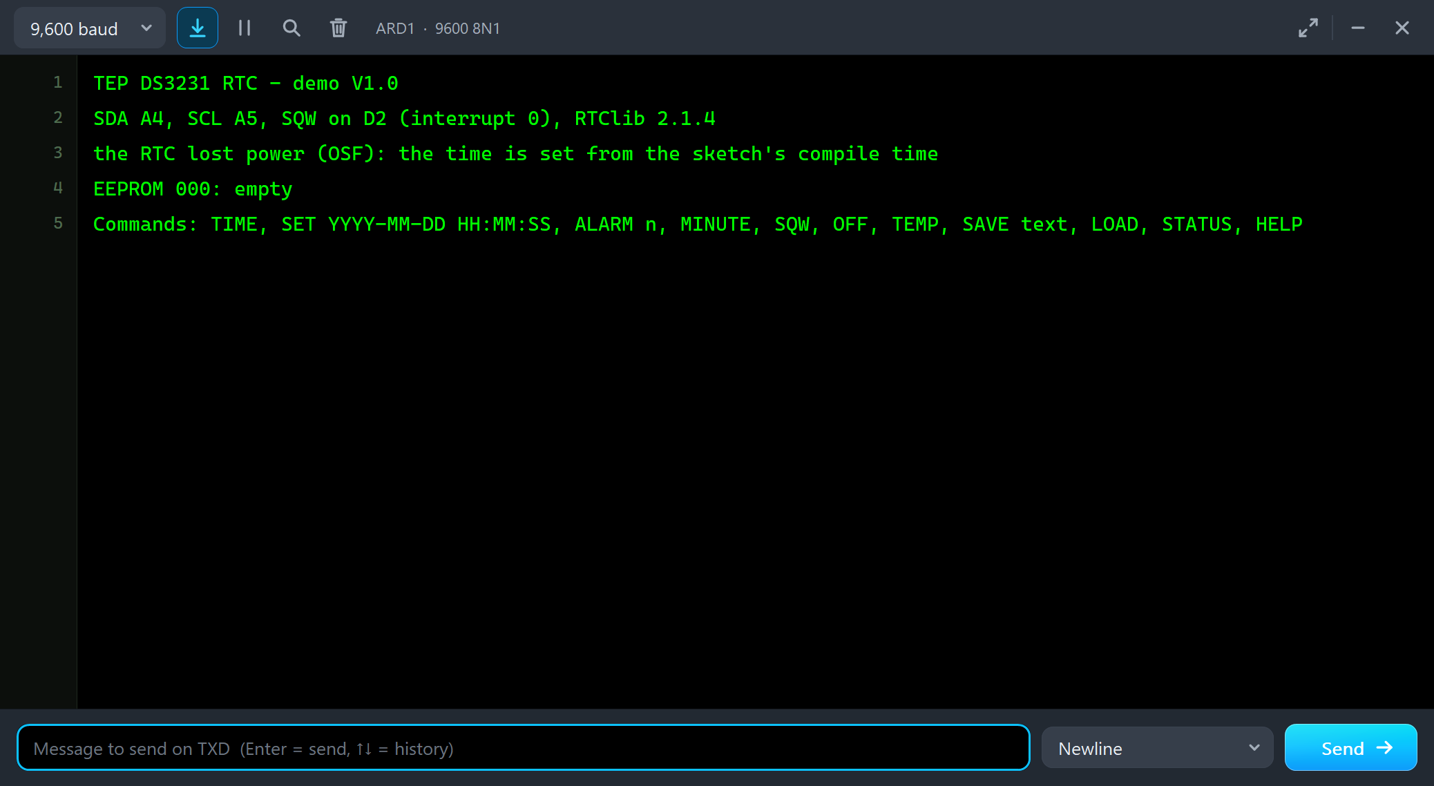
TEP DS3231 RTC - demo V1.0
SDA A4, SCL A5, SQW on D2 (interrupt 0), RTClib 2.1.4
the RTC lost power (OSF): the time is set from the sketch's compile time
EEPROM 000: empty
Commands: TIME, SET YYYY-MM-DD HH:MM:SS, ALARM n, MINUTE, SQW, OFF, TEMP, SAVE text, LOAD, STATUS, HELP
U2 opens its own window, DS3231 RTC Module, with the look of our TEP Serial Monitor Advance for Proteus. It has three tabs, Clock, Event log and Tests, plus Settings and Help behind the gear and question mark icons:
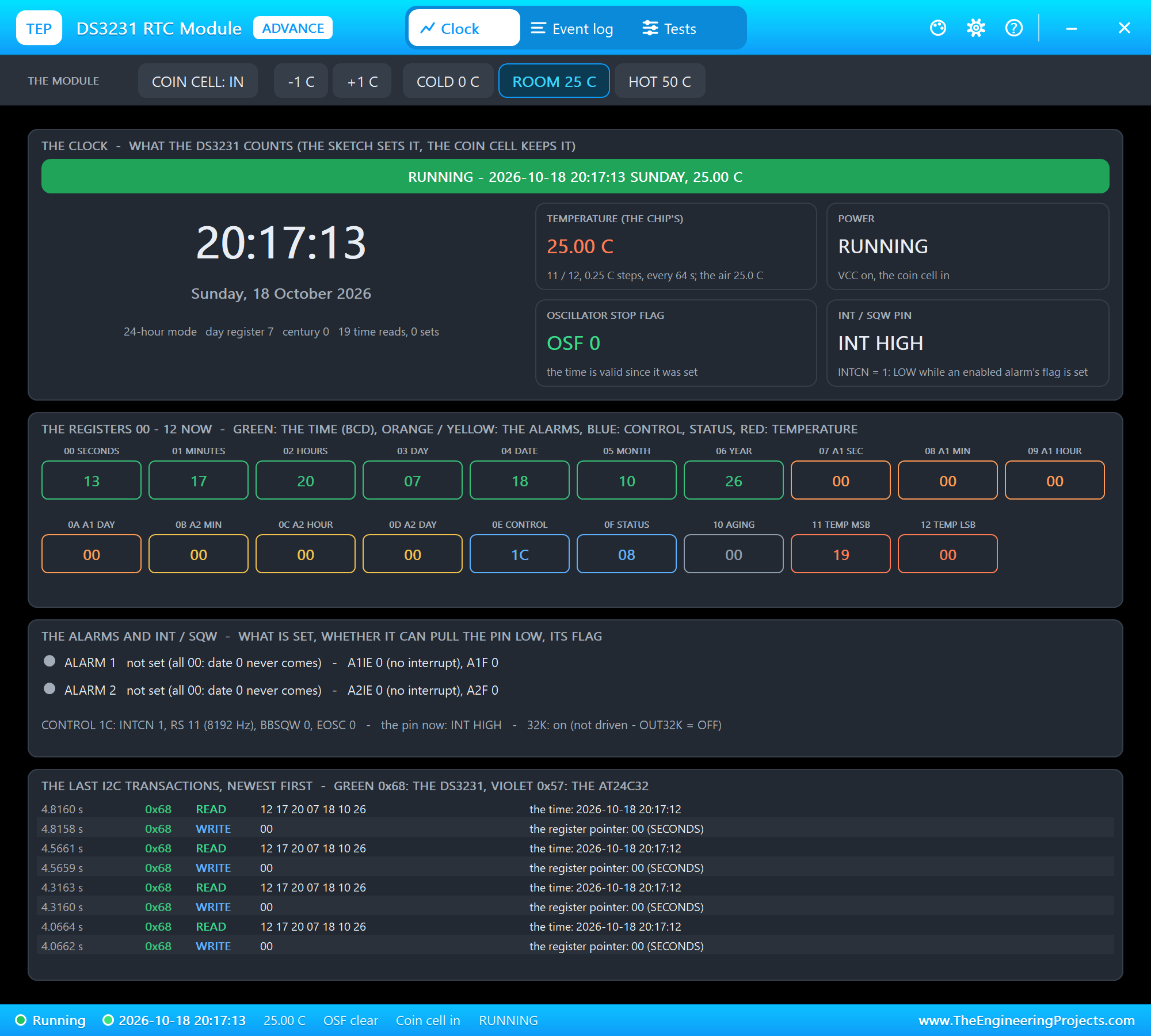
The Clock page shows the time as the chip counts it with the date and the day of the week, four tiles - the chip's temperature, power, OSF and the INT / SQW pin -, the registers 00 - 12 exactly as the sketch would read them now, the alarms and the control register in words, and the last I2C transactions, decoded. Most of them are the sketch's time reads: the pointer 00, then seven bytes - 0x12, 0x17, 0x20 is 20:17:12 in BCD.
Alarm 1: ALARM 5
We typed TEMP, STATUS and ALARM 5 in ARD2's monitor:
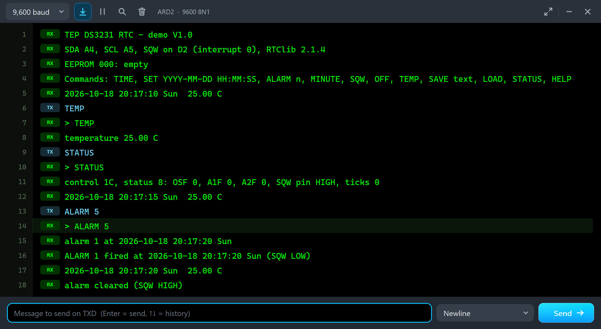
2026-10-18 20:17:10 Sun  25.00 C
TEMP
> TEMP
temperature 25.00 C
STATUS
> STATUS
control 1C, status 8: OSF 0, A1F 0, A2F 0, SQW pin HIGH, ticks 0
2026-10-18 20:17:15 Sun  25.00 C
ALARM 5
> ALARM 5
alarm 1 at 2026-10-18 20:17:20 Sun
ALARM 1 fired at 2026-10-18 20:17:20 Sun (SQW LOW)
2026-10-18 20:17:20 Sun  25.00 C
alarm cleared (SQW HIGH)
RTClib wrote the alarm into 07 - 0A and enabled its interrupt: the control register went from 1C to 1D. Five seconds later the seconds matched, A1F went to 1 and INT / SQW went LOW - the pop-up at that moment:
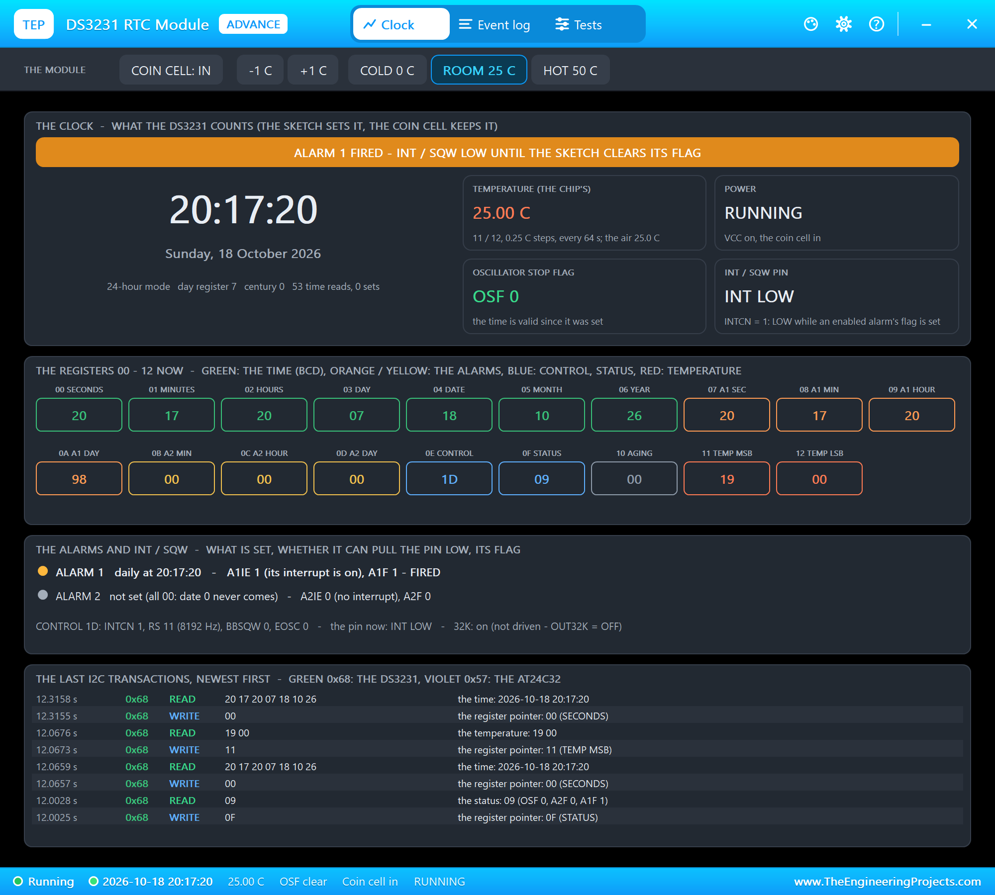
The status register shows 09: the 32 kHz bit and A1F. The pin stays LOW until the sketch writes A1F back to 0 - in the demo two seconds later, and the SQW LED on the board goes out.
The EEPROM and the Square Wave
Then SAVE Hello from TEP, LOAD, SQW and STATUS:
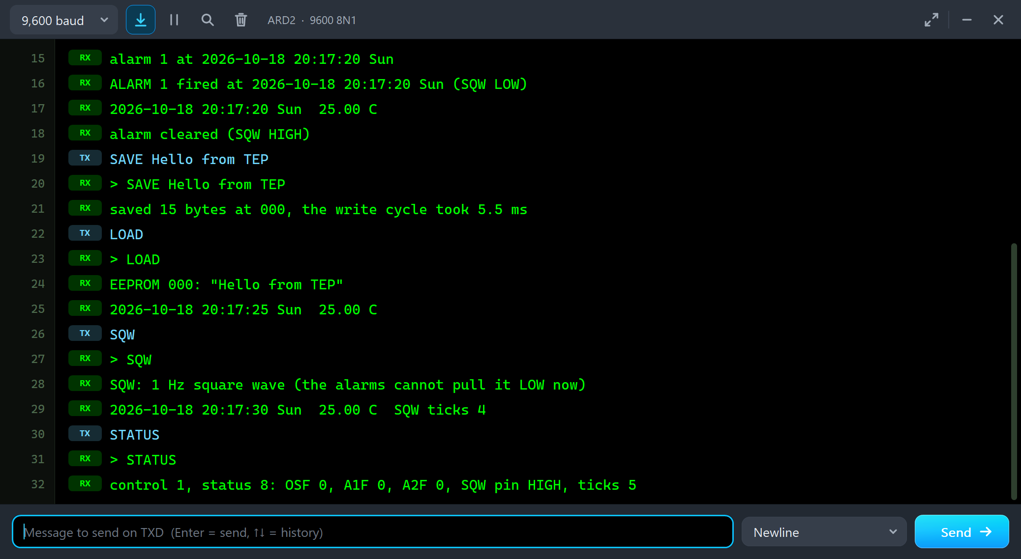
SAVE Hello from TEP
> SAVE Hello from TEP
saved 15 bytes at 000, the write cycle took 5.5 ms
LOAD
> LOAD
EEPROM 000: "Hello from TEP"
2026-10-18 20:17:25 Sun  25.00 C
SQW
> SQW
SQW: 1 Hz square wave (the alarms cannot pull it LOW now)
2026-10-18 20:17:30 Sun  25.00 C  SQW ticks 4
STATUS
> STATUS
control 1, status 8: OSF 0, A1F 0, A2F 0, SQW pin HIGH, ticks 5
The note took one page write. After the STOP the AT24C32 needs 5 ms to write it, and it does not acknowledge its address meanwhile - the sketch polled it until it answered and measured 5.5 ms. The EEPROM tool shows the same from the module's side:
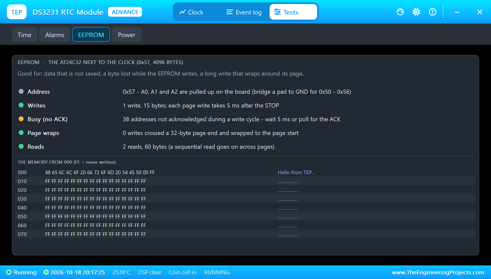
The 38 refused addresses are the sketch's polls during those 5 ms. A write that crosses a 32-byte page end would wrap to the start of its page - the tool counts that too. With SQW the control register became 01: INTCN 0 and RS 00, the 1 Hz square wave:
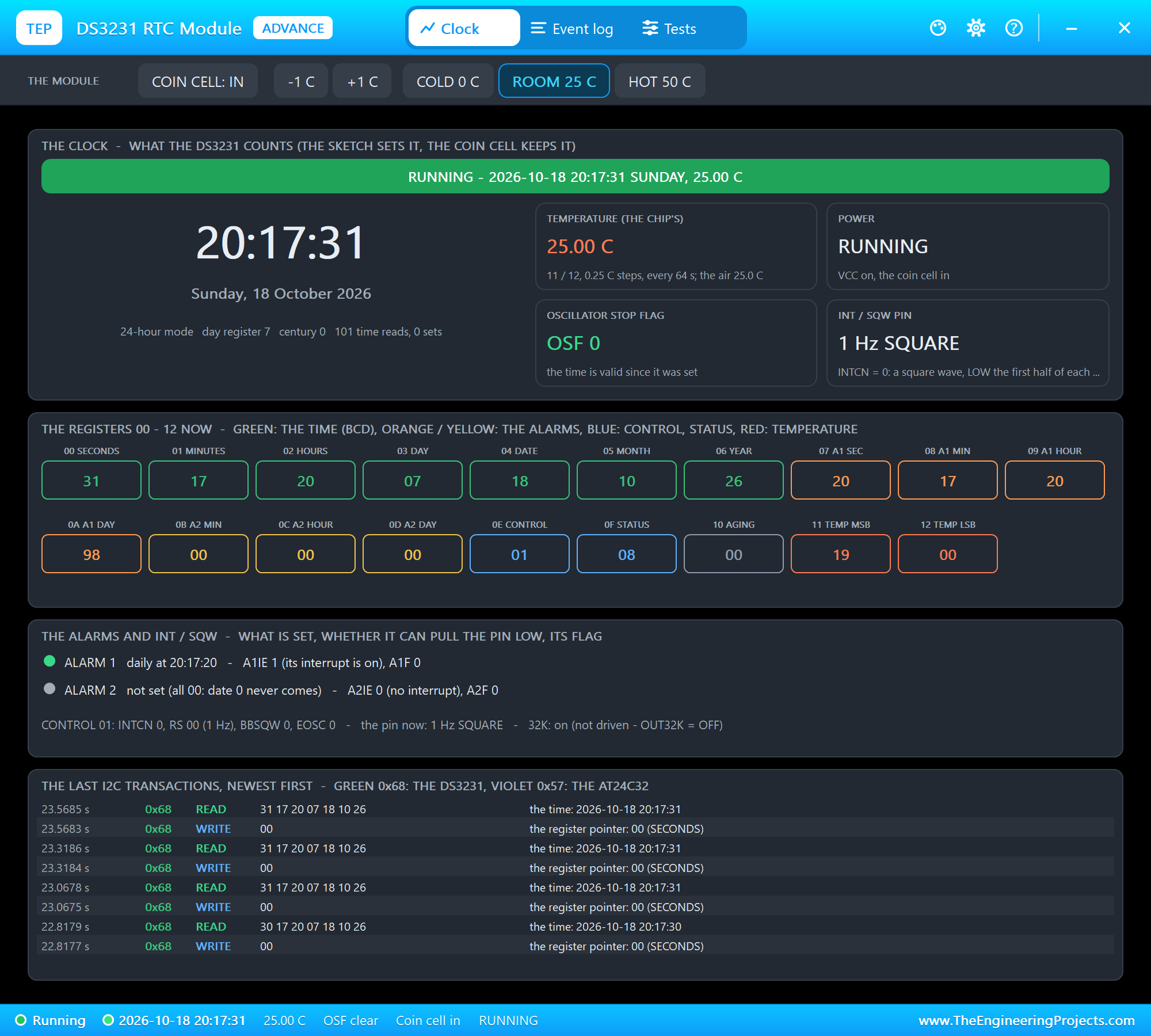
The pin goes LOW at the start of every second and HIGH half a second later, and the SQW LED on the board blinks with it. The alarms still set their flags, but they cannot pull the pin LOW now - OFF turns it back into INT.
The Coin Cell, Alarm 2 and the Temperature
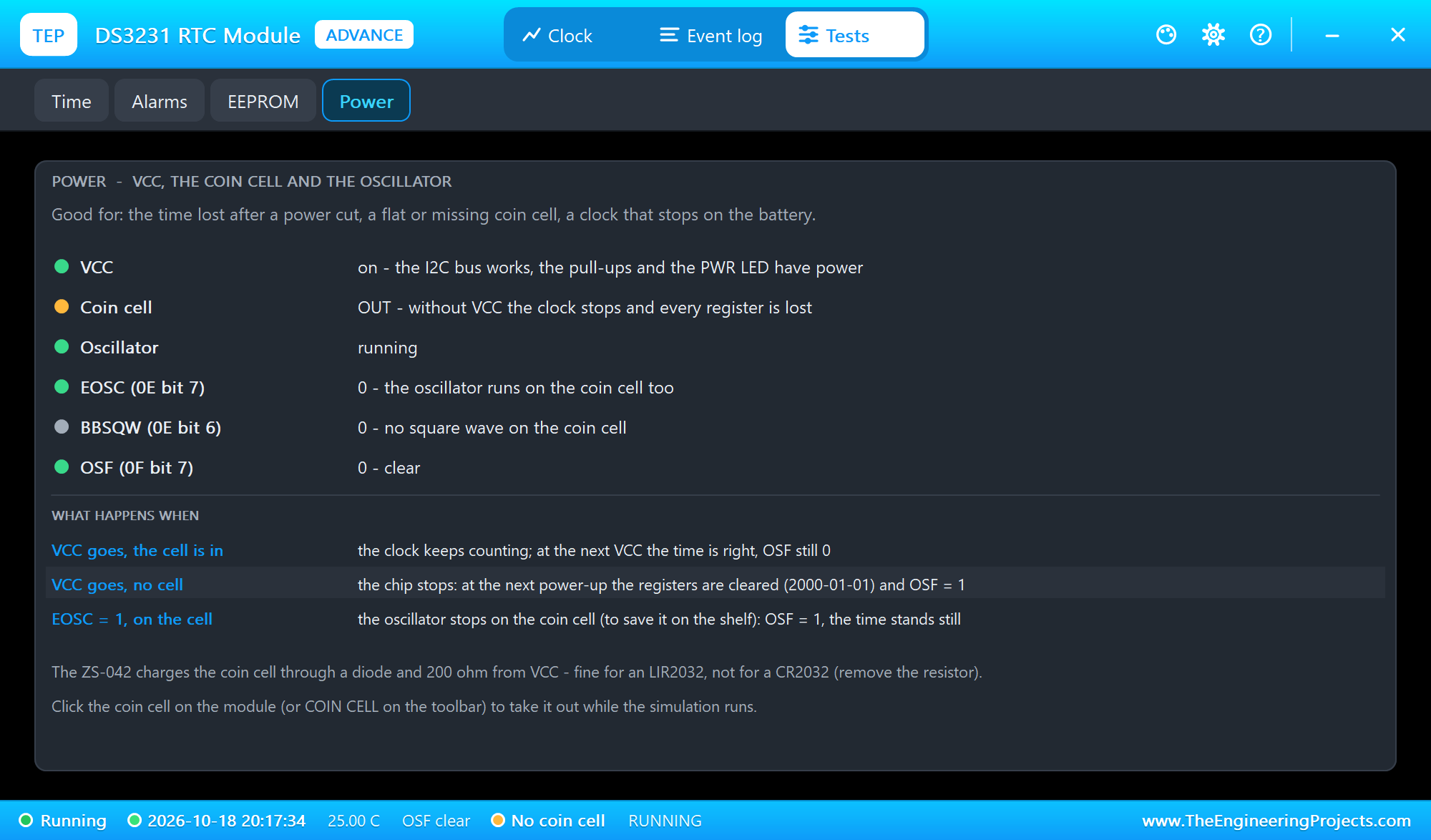
We clicked COIN CELL on the pop-up's toolbar to take the cell out:
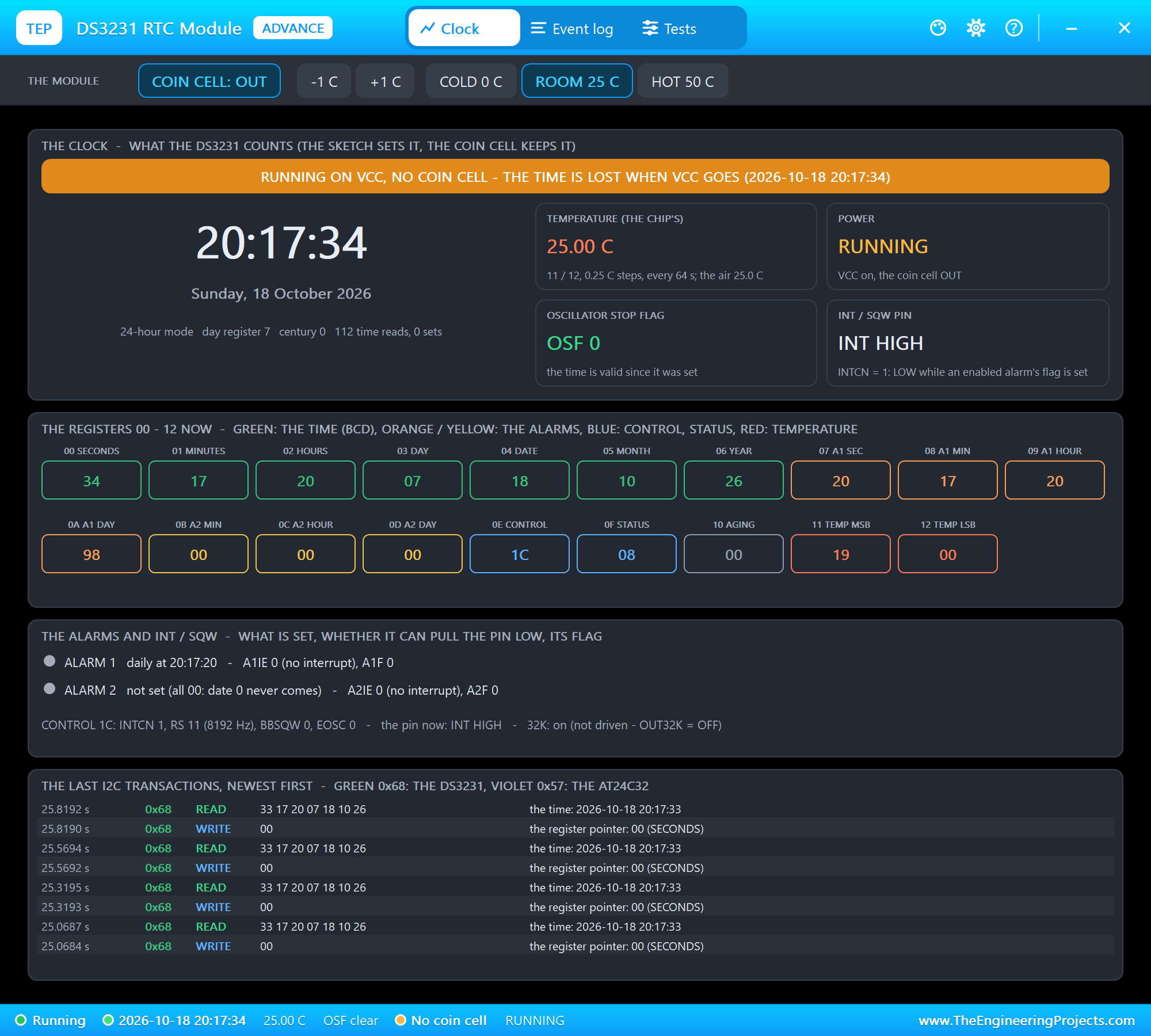
The clock runs on, but now nothing would keep it when VCC goes. The Power tool explains what happens in each case:
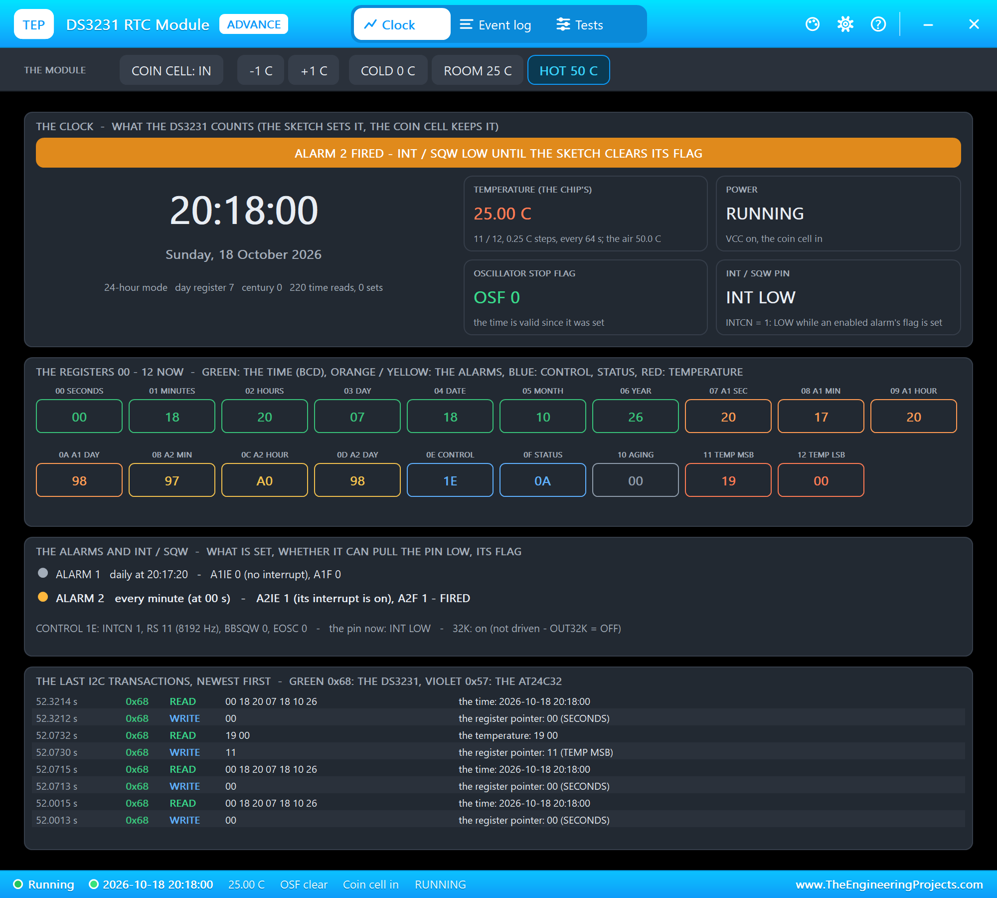
With the cell back in, we clicked HOT 50 C and typed MINUTE. Alarm 2 fired at the next full minute:
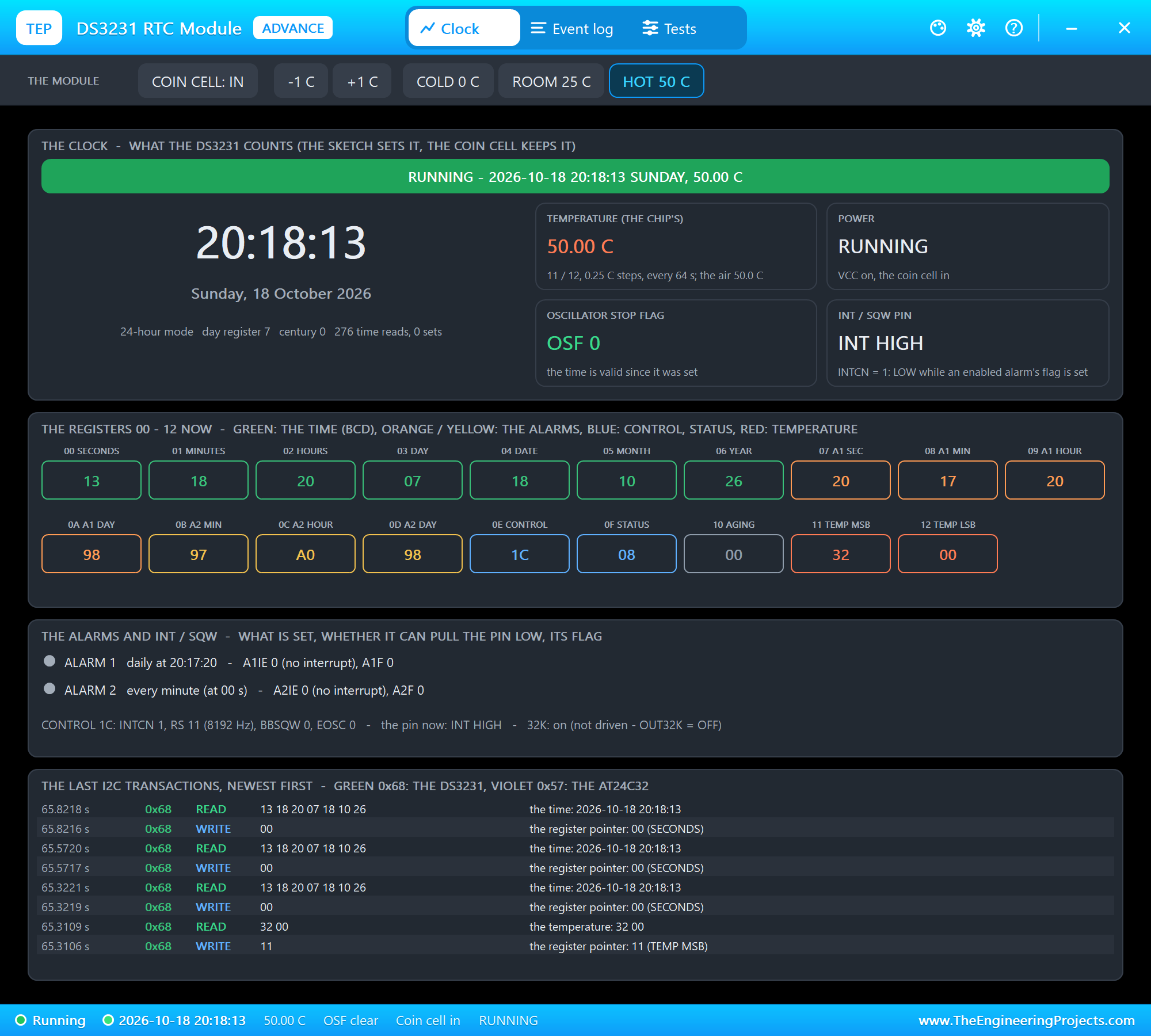
And the temperature? The air was 50 C at once, but the chip converts only every 64 s - until then registers 11 and 12 still said 25.00. After the conversion they read 0x32, 0x00 - 50.00 C:
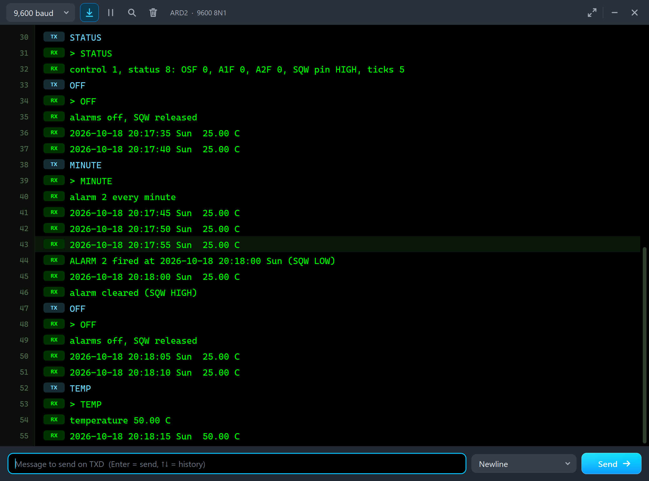
MINUTE
> MINUTE
alarm 2 every minute
2026-10-18 20:17:45 Sun  25.00 C
2026-10-18 20:17:50 Sun  25.00 C
2026-10-18 20:17:55 Sun  25.00 C
ALARM 2 fired at 2026-10-18 20:18:00 Sun (SQW LOW)
2026-10-18 20:18:00 Sun  25.00 C
alarm cleared (SQW HIGH)
OFF
> OFF
alarms off, SQW released
2026-10-18 20:18:05 Sun  25.00 C
2026-10-18 20:18:10 Sun  25.00 C
TEMP
> TEMP
temperature 50.00 C
2026-10-18 20:18:15 Sun  50.00 C
The Test Tools
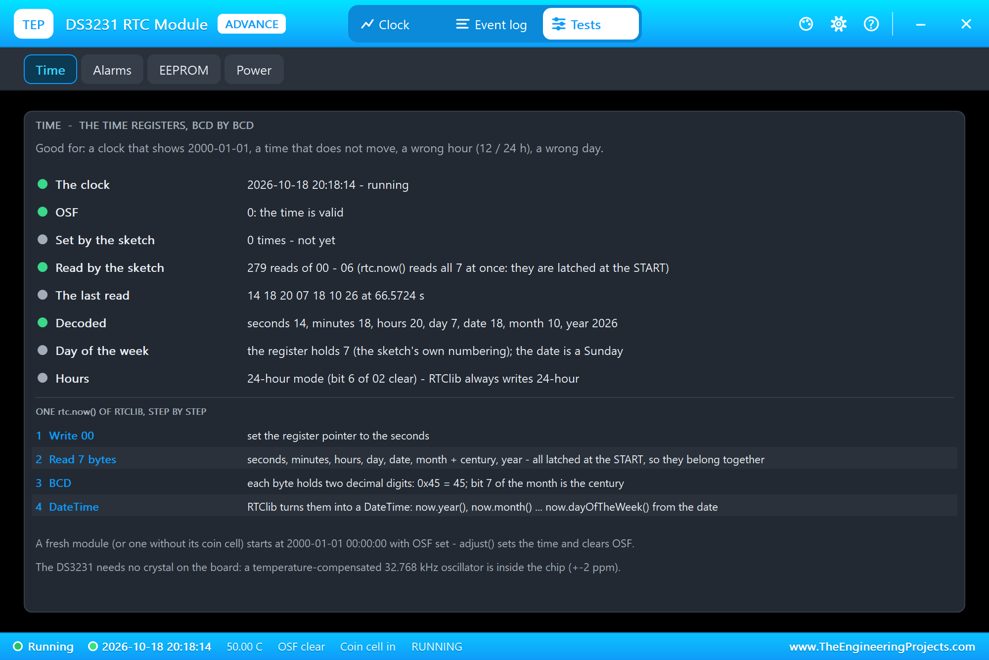
The Time tool is good for a clock that shows 2000-01-01, a time that does not move, a wrong hour or a wrong day. It shows whether the clock runs, OSF, how often the sketch set and read the time, and the last read byte by byte in BCD.
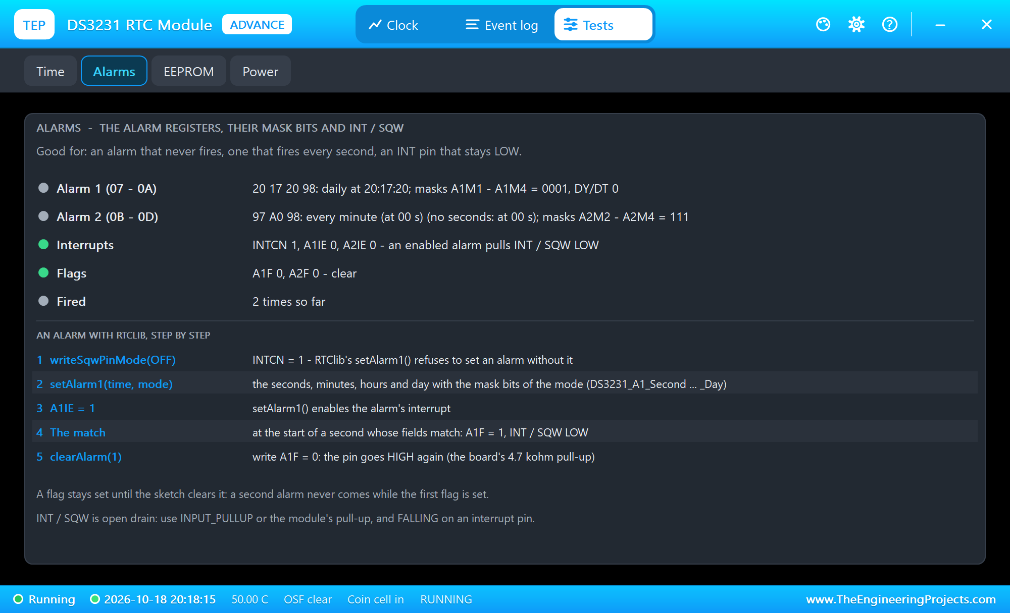
The Alarms tool is good for an alarm that never fires, one that fires every second, or an INT pin that stays LOW: both alarms' registers with their mask bits, INTCN and the interrupt enables, the flags, and how RTClib sets an alarm step by step. The EEPROM and Power tools are shown above.
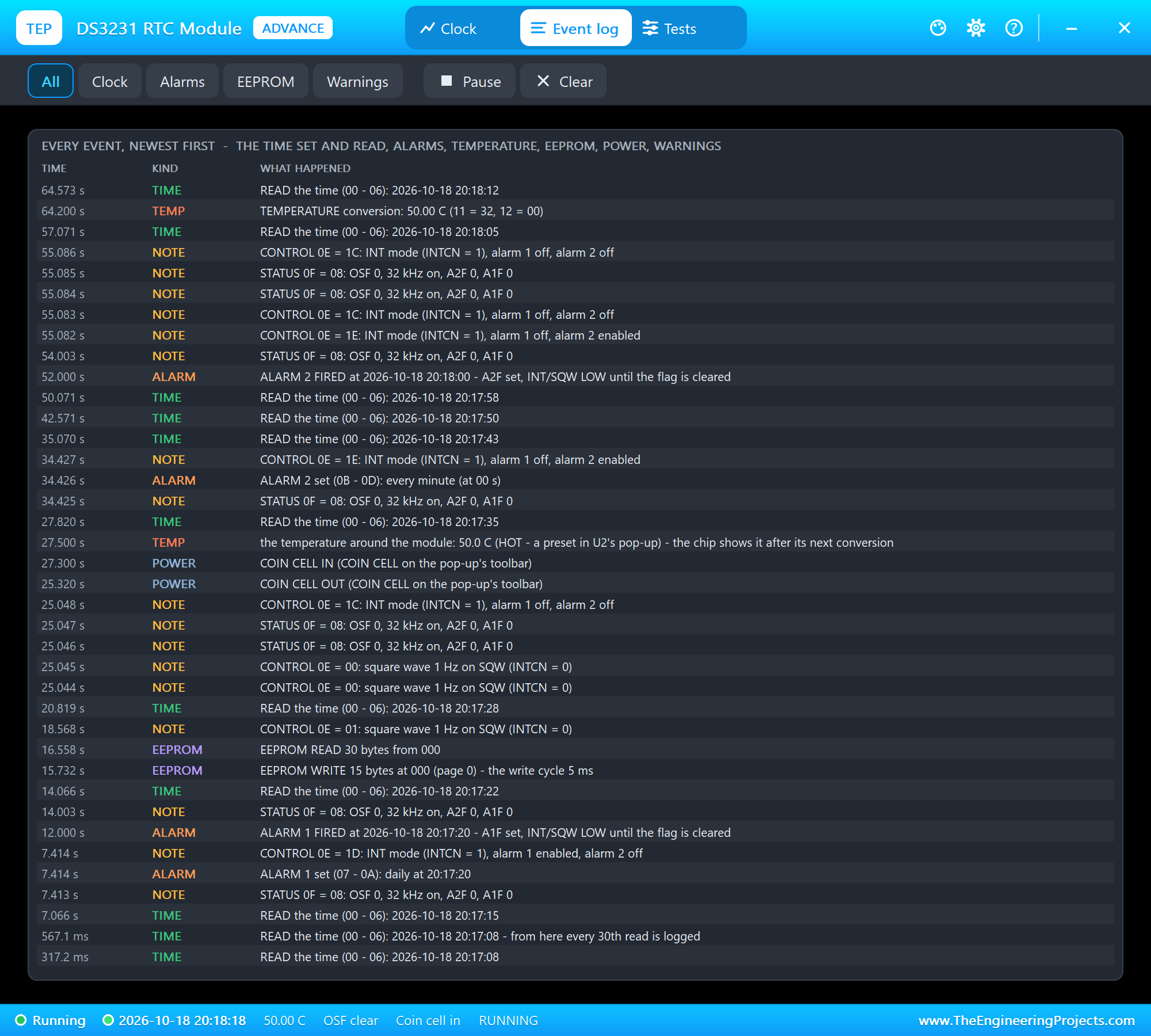
The Event log lists everything that happened, newest first: the time set and read (the first reads, then every 30th), the alarms, the temperature conversions, the EEPROM, power and warnings. Filter it, pause it, or clear it.
The Coin Cell and an Alarm with the Mouse
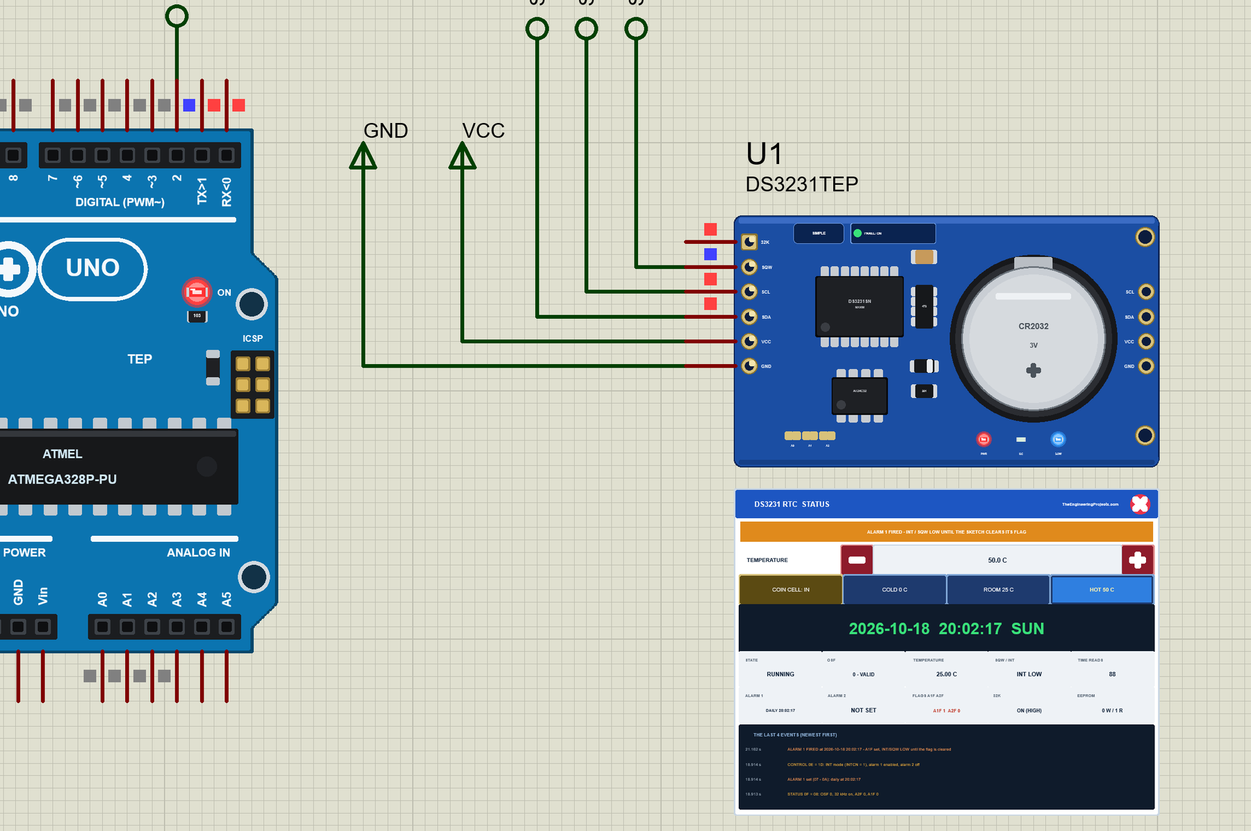
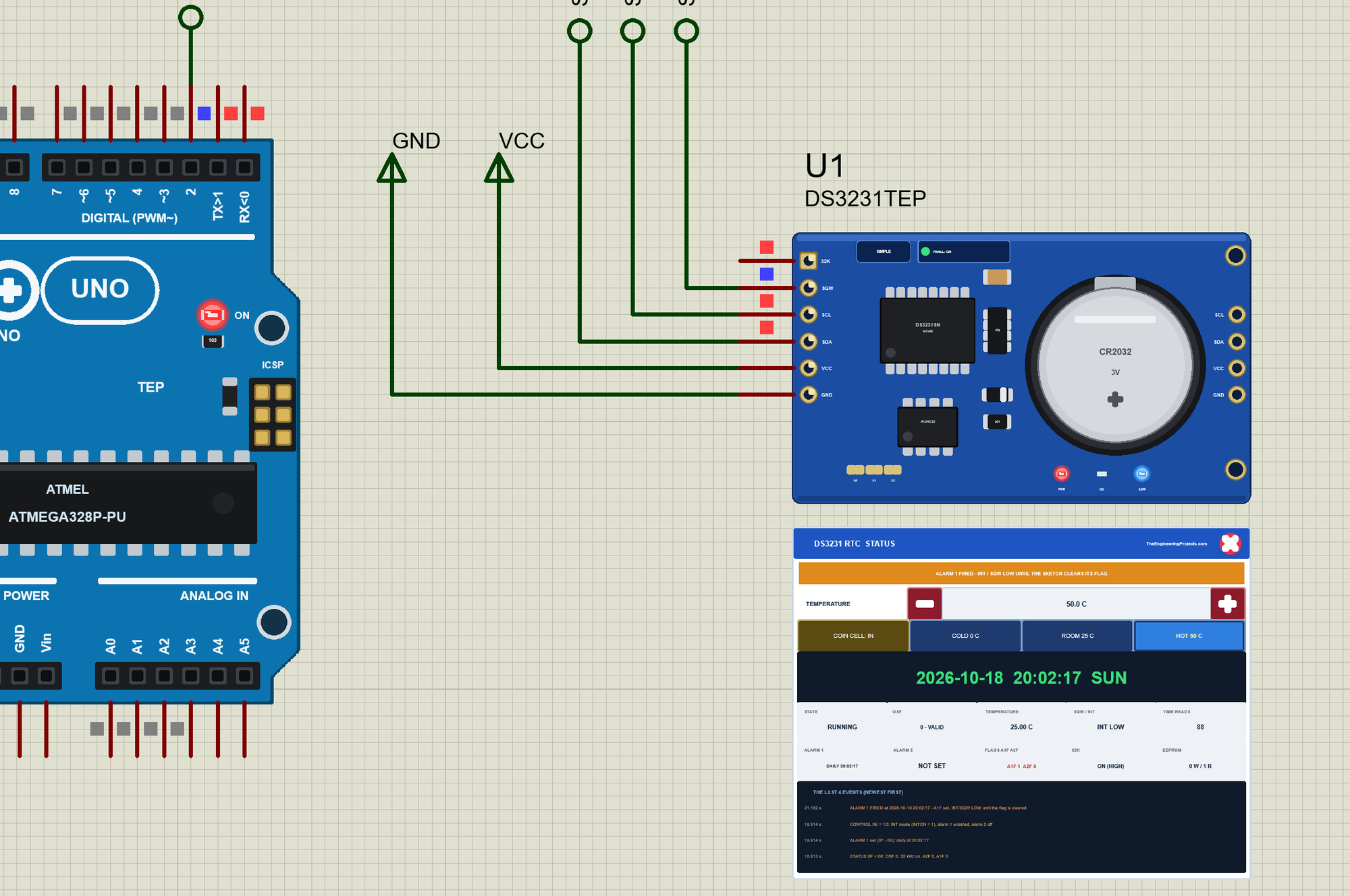
Back to node 1, the Simple part. We clicked the coin cell on the module while the simulation ran - it came out of its holder:
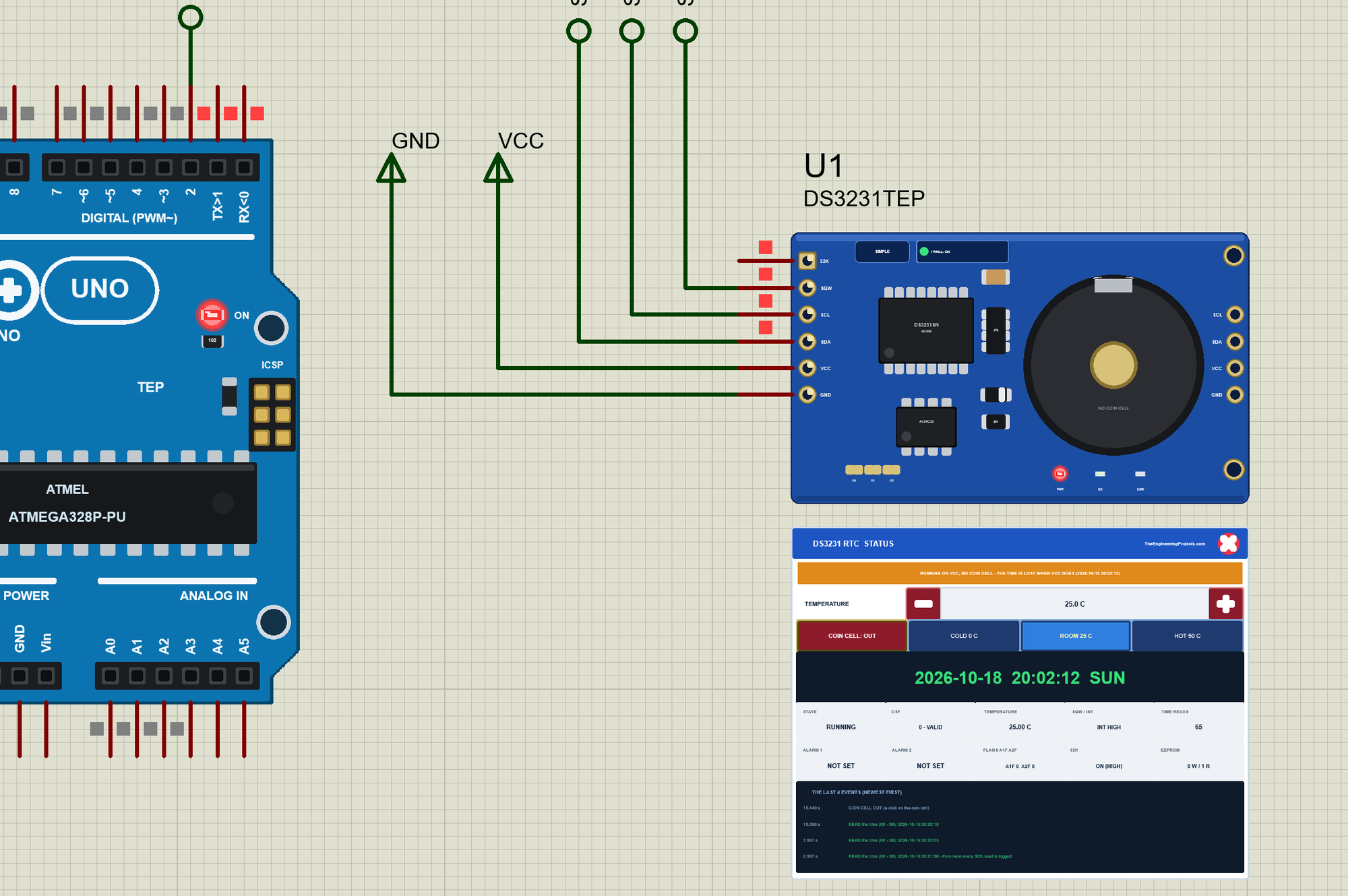
COIN CELL on the panel put it back, + and HOT 50 C changed the temperature, and ALARM 3 in ARD1's monitor set an alarm three seconds ahead:
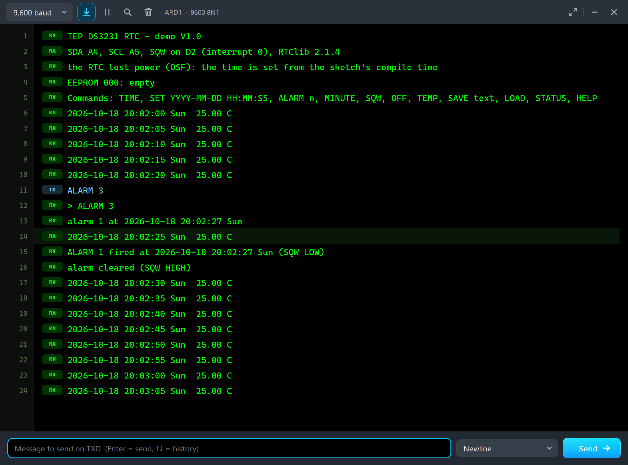
2026-10-18 20:02:00 Sun  25.00 C
2026-10-18 20:02:05 Sun  25.00 C
2026-10-18 20:02:10 Sun  25.00 C
2026-10-18 20:02:15 Sun  25.00 C
2026-10-18 20:02:20 Sun  25.00 C
ALARM 3
> ALARM 3
alarm 1 at 2026-10-18 20:02:27 Sun
2026-10-18 20:02:25 Sun  25.00 C
ALARM 1 fired at 2026-10-18 20:02:27 Sun (SQW LOW)
alarm cleared (SQW HIGH)
Note the time on node 1: it started at the sketch's compile time, not at the PC's time - exactly what a new module does with this sketch. Every click on the coin cell and on the panel was read back from the model on the first try.
The Simulation Log
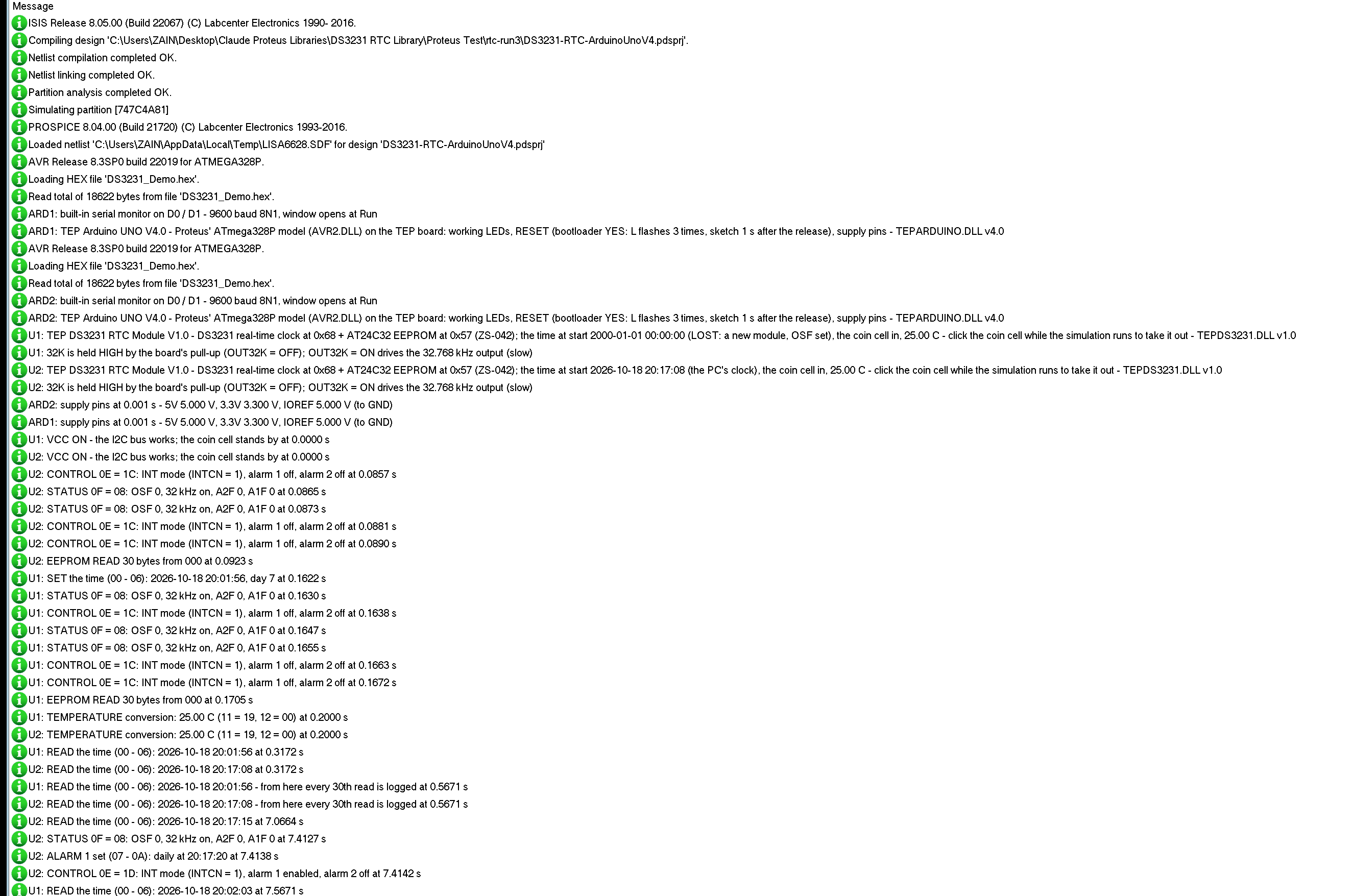
The parts also write to the simulation log of Proteus, with the exact simulation time. These lines show node 1 setting its time, the first conversion and reads, and alarm 1 on node 2:
U1: VCC ON - the I2C bus works; the coin cell stands by at 0.0000 s
U1: SET the time (00 - 06): 2026-10-18 20:01:56, day 7 at 0.1622 s
U1: TEMPERATURE conversion: 25.00 C (11 = 19, 12 = 00) at 0.2000 s
U1: READ the time (00 - 06): 2026-10-18 20:01:56 at 0.3172 s
U2: READ the time (00 - 06): 2026-10-18 20:17:08 at 0.3172 s
U2: ALARM 1 set (07 - 0A): daily at 20:17:20 at 7.4138 s
U2: CONTROL 0E = 1D: INT mode (INTCN = 1), alarm 1 enabled, alarm 2 off at 7.4142 s
U2: ALARM 1 FIRED at 2026-10-18 20:17:20 - A1F set, INT/SQW LOW until the flag is cleared at 12.0000 s
The DS3231's times are the simulation's. Its clock started from the property: 2000-01-01 on U1 until the sketch set it, the PC's time on U2.
How the Model Works
The model counts seconds from a base time and the simulation time at which that second began - the countdown chain of the real chip. A read of the time copies all seven registers at the START condition, in BCD, with the 12-hour bit, the century and the day register. A write of the seconds restarts the second. At every new second the model checks both alarms against their mask bits, and a model callback lands exactly on the next second, the end of a conversion and the next edge of the square wave, so INT / SQW changes at its exact time. VCC and the coin cell decide whether the chip runs; with neither, the registers go back to their power-on values and OSF is set. The AT24C32 keeps its 4096 bytes in pages of 32, writes a page 5 ms after the STOP and does not acknowledge its address meanwhile.
Troubleshooting
- "no DS3231 at 0x68": SDA and SCL swapped, VCC missing (the PWR LED), or the part has no model - TEPDS3231.DLL in MODELS and beside the project.
- The time is 2000-01-01 after every Run: TIME = LOST or BATTERY = OUT - the sketch must set it with lostPower() and adjust().
- An alarm never fires: INTCN is 0 (the square wave is on), the alarm's interrupt is off, or the flag of the last alarm was never cleared - Alarms shows each bit.
- SQW stays LOW: an alarm flag is set - clearAlarm() releases it.
- The EEPROM loses bytes: the next access came during the 5 ms write cycle, or the write crossed a 32-byte page end - EEPROM shows both.
- The temperature does not change: the chip converts every 64 s - wait for the next conversion.
- No part or no monitor: TEPDS3231.DLL or TEPARDUINO.DLL is missing; a closed monitor opens again with a click on the UNO's USB port.
Things to Know Before Using a Real DS3231 Module
- The coin cell: the ZS-042 charges it from VCC through a diode and a 200 ohm resistor - fine for a rechargeable LIR2032, not for a CR2032: remove the resistor (or the diode) when you use a CR2032.
- A new module: it starts with OSF set - check lostPower() and set the time once with adjust().
- The pull-ups: the module has its own 4.7 kohm pull-ups on SDA, SCL, SQW and 32K; with several I2C modules on one bus, too many pull-ups in parallel can be too strong.
- INT / SQW: it is open drain - use FALLING on an interrupt pin and keep the pull-up.
- The accuracy: +-2 ppm from 0 to 40 C, about a minute a year; the aging register can trim it.
Limitations of the Simulation
- Not modelled: the aging offset's effect and the oscillator's ppm error (the clock is exact; the aging register is stored), the current, the coin cell's voltage and charging, the EEPROM's A0 - A2 pads (always 0x57), the 400 kHz timing limits.
- The model's own choices: a conversion takes 0.2 s, the EEPROM's write cycle 5 ms, the 1 Hz square wave goes LOW at each new second and HIGH half a second later, 32K is driven only with OUT32K = ON (65,536 edges a second slow the simulation).
- The badge, the LEDs, the coin cell drawn beside the chips, the panel button and the panels are TEP additions.
- The model is our own implementation written from the DS3231 and AT24C32 datasheets. This library is not made or endorsed by Analog Devices / Maxim Integrated, Microchip / Atmel, Adafruit or Labcenter.
- Licences: the HEX file contains RTClib 2.1.4 and Adafruit BusIO 1.17.4 (both MIT licence - the notices are in the README) and the Arduino AVR core 1.8.6 with LGPL-licensed code - the source link is in the README.
- Tested in Proteus 8.5 in October 2026 (the demo as shipped on two Arduino UNO V4.0 boards with their built-in monitors: the time set on a new module, alarm 1 and alarm 2, the EEPROM, the square wave, the coin cell out and in, the temperature after a conversion and the four tools on the Advance part; the coin cell and the panel with the mouse on the Simple one; 71.6 s of simulation took 246 s with the pop-up and both monitors open, about 0.29 x real time). Proteus 7 is not supported.
So, that was all about the DS3231 RTC Module Library for Proteus V1.0. I hope the registers, the alarms, OSF and the coin cell of the DS3231 are clear now, and that your clock or data logger keeps the right time from the first run. If you use the DS3231 RTC Module Library for Proteus in a project, please share it in the comments or in our forum, and if you have any questions, ask in the comments and I will help you out. Till the next tutorial, take care and have fun!