Hello friends, I hope you all are doing great. Today, I am going to share the new Micro SD Card Module Library for Proteus V1.0. The micro SD card module is how an Arduino keeps data: a data logger writes its readings to a CSV file, a game loads its levels, a clock keeps a record of every event, and you take the card to your PC afterwards. The Arduino talks to the card over SPI with four wires, and the SD library does the rest. Until now there was no SD card module in Proteus that the real SD library could read and write.
Behind the parts sits our own model, written from the SD card specification. The card wakes up in SD mode and enters SPI mode on CMD0, answers CMD8, needs ACMD41 until it has finished its power-up, reports itself as a standard-capacity card with CMD58, then reads and writes blocks of 512 bytes with the data tokens, the CRC and the busy time of a real card. On the card is a real FAT16 file system - a 64 MB card partitioned as a PC formats it - so the unmodified SD library mounts it, lists its folders, reads files and writes new ones. You get a Simple device with a STATUS panel that is a file browser, and an Advance device with a pop-up window that also shows every SPI command. The demo runs on our Arduino UNO V4.0.
NOTICE: an SD card is easy to fake: a part that hands the sketch a file when it asks for one. We wanted more. Our card does not know what a file is - it only knows blocks, like the real one. The SD library on the Arduino finds the partition, the FAT and the folders on its own, and every file it writes goes through the same commands as on your bench. Pull the card out and the sketch gets no answer; put it back and it must start the card again. It took our team a lot of hard work. Your feedback is the fuel that keeps us going, so please tell us what you think in the comments below or in the Micro SD Card Module board of our forum. And if our free libraries help you, you can buy us a coffee. So, let's get started with the Micro SD Card Module Library for Proteus V1.0:
What is the Micro SD Card Module?
The common micro SD card module is a small blue board with a push-push socket for a micro SD card, an AMS1117 regulator that makes the card's 3.3 V from the Arduino's 5 V, and a 74LVC125A buffer that turns the Arduino's 5 V signals into 3.3 V ones. It has six pins: GND, VCC, MISO, MOSI, SCK and CS. An SD card itself has two bus modes: the fast 4-bit SD mode of cameras and phones, and the simpler SPI mode that every microcontroller can use. The Arduino uses SPI mode.
| Micro SD card module | |
|---|---|
| Supply | 5 V on VCC (the AMS1117 makes 3.3 V for the card) |
| Interface | SPI mode 0: MOSI, MISO, SCK and CS (any free pin) |
| Level shifter | 74LVC125A: the 5 V signals to 3.3 V |
| Cards | micro SD (SDSC up to 2 GB) and micro SDHC (up to 32 GB), FAT16 or FAT32 |
| Blocks | 512 bytes: every read and write is a whole block |
| SPI clock | up to 25 MHz; 100 - 400 kHz while the card initialises |
| Arduino library | the SD library that comes with the Arduino IDE (1.3.0 in the demo) |
| Our model | a 64 MB SDSC card with one FAT16 partition |
SPI Mode: How the Card Wakes Up
A card starts in SD mode. The sketch first sends at least 74 clocks with CS HIGH, then CMD0 with CS LOW: the card switches to SPI mode and answers R1 01 - idle. CMD8 asks whether the card is a version 2.00 card that accepts the voltage, and the card echoes the pattern 1AA back. Then the sketch repeats CMD55 + ACMD41 until the card has finished its power-up and answers R1 00. CMD58 reads the OCR, which tells a standard-capacity card (byte addresses) from an SDHC card (block addresses). From then on the card reads and writes blocks.
| Command | What it does |
|---|---|
| CMD0 | GO_IDLE_STATE: SD mode to SPI mode (with CS LOW and the CRC 95) |
| CMD8 | SEND_IF_COND: the version 2.00 check (CRC 87, the R7 echo of 1AA) |
| CMD55 + ACMD41 | SD_SEND_OP_COND: repeated until the card is ready (R1 00) |
| CMD58 | READ_OCR: powered up? SDSC or SDHC? |
| CMD9 / CMD10 | the CSD (the card's size) and the CID (who made it) |
| CMD17 / CMD18 | read one block / read blocks until CMD12 |
| CMD24 / CMD25 | write one block / write blocks until the stop token |
| CMD13 | SEND_STATUS: the R2 status after a write |
Every command is 6 bytes: the command, a 32-bit argument and a CRC. The answer comes one byte later (one FF byte, called NCR). A block read answers R1 00, then the data token FE, 512 bytes and a 16-bit CRC. A block write sends FE, 512 bytes and a CRC; the card answers 05 (accepted) and then keeps MISO LOW while it programs the block.
FAT16: What is on the Card
The card only knows blocks. The file system is a convention on top of them. Block 0 is the MBR with the partition table; our partition starts at block 2048, as a PC places it. Its first block is the boot sector with the layout of the volume, then come two copies of the FAT (the table that links the clusters of each file), the root folder with 512 entries of 32 bytes, and the data area, cut into clusters of 2 KB. A file is a folder entry - its 8.3 name, size, date and first cluster - and a chain of clusters in the FAT.
What's New in Micro SD Card Module Library for Proteus V1.0
- SPI mode at the bit level: MOSI read on every rising edge of SCK, MISO changed on the falling edges - the SPI clock measured on every byte.
- The card's start-up: SD mode until CMD0, CMD8, ACMD41 until the card is ready after 50 ms, CMD58 - with R1 and its error bits.
- Blocks as on the bench: the data token, the CRC16, the data response 05 and the busy time after every write.
- A 64 MB card with FAT16: the MBR, the boot sector, two FATs, the root folder and 2 KB clusters - the SD library mounts it as it is.
- Four cards at start: DEMO (files and folders to read), EMPTY (formatted), RAW (never formatted) and NONE.
- A file browser: click a folder to open it, a file to see its first lines - or its first bytes in hex.
- A clickable card: pull it out while the simulation runs, put it back - the sketch must start it again.
- Every SPI command decoded in the Advance pop-up, with the block and the file it belongs to.
- Three test tools on the Advance device: Init and SPI, Commands, File system.
- A two-node demo on our Arduino UNO V4.0 with the SD library: a data logger, DIR, CAT, WRITE, DEL, MKDIR, RMDIR, INFO and INIT from the serial monitor.
- A compact package: about 1.28 MB, without the C++ source code of the model.
Two Devices: Simple and Advance
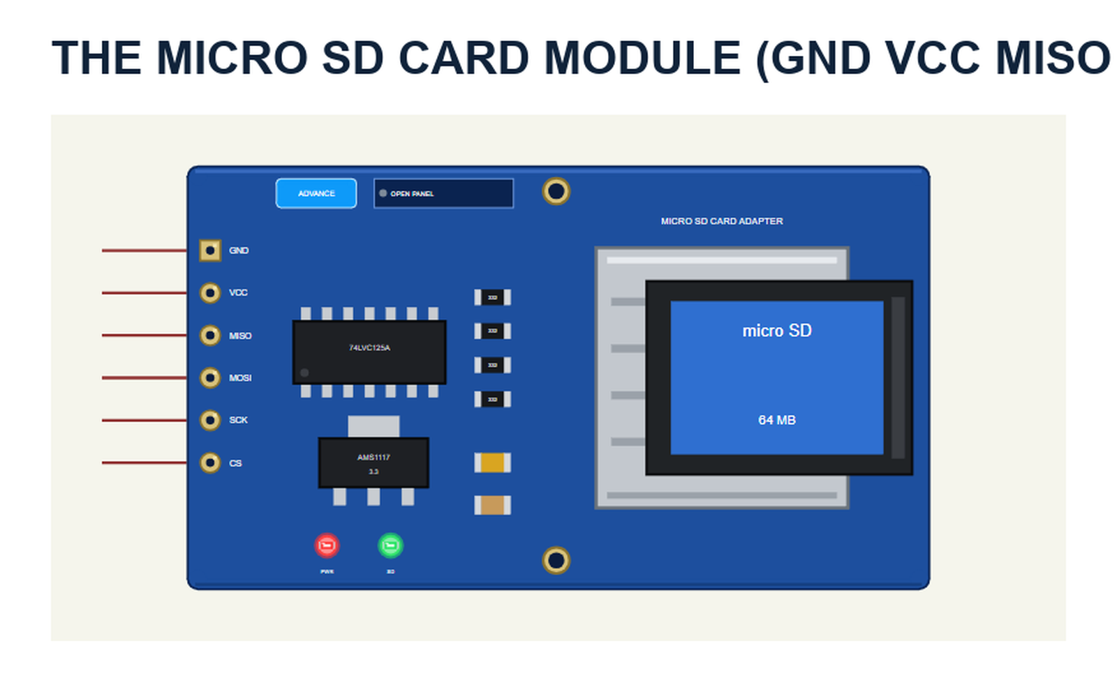
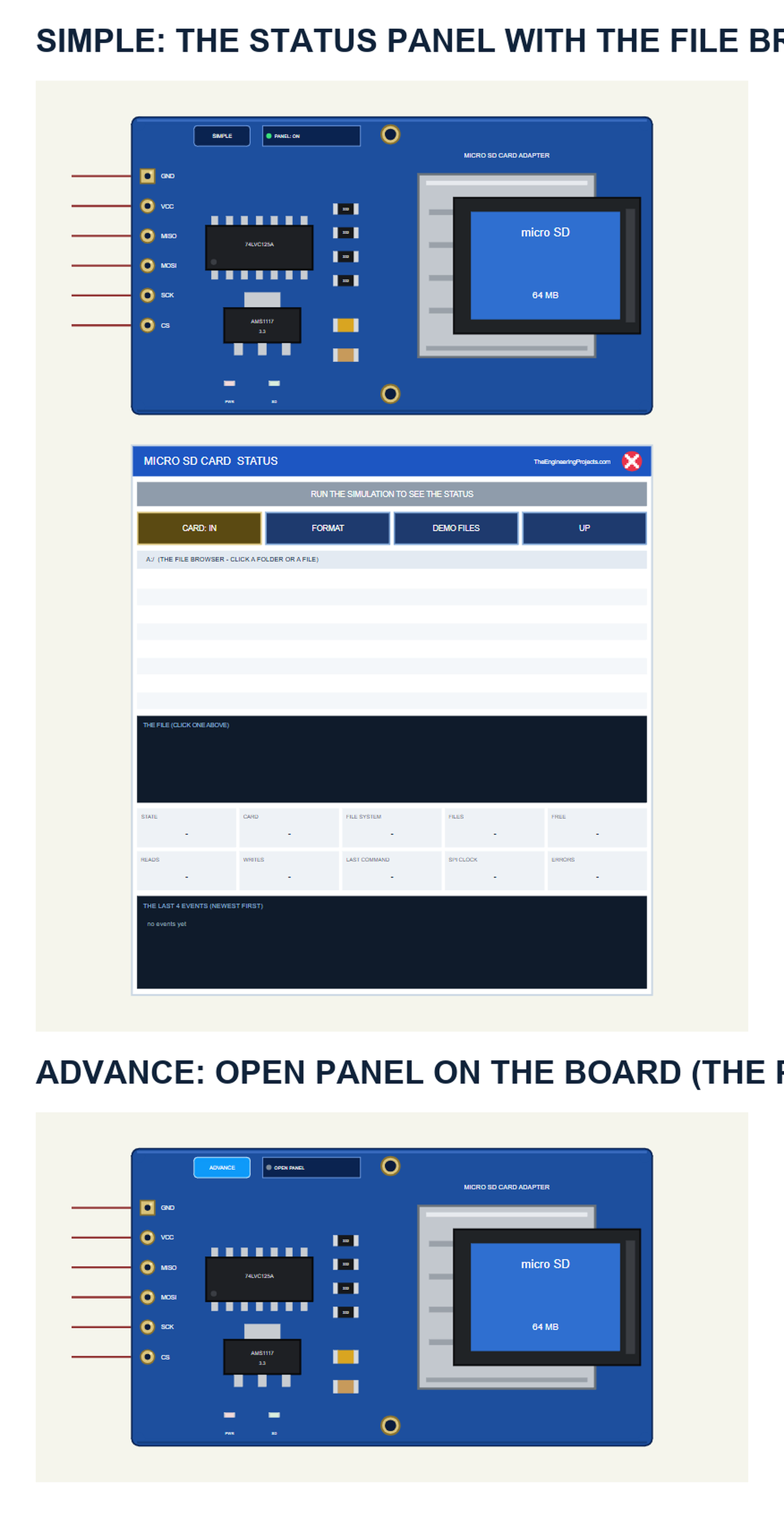
The part is the module seen from above, drawn at about its real size next to the Arduino UNO: the 74LVC125A level shifter, the AMS1117 regulator, the four 332 resistors and the two capacitors, the 6-pin header GND VCC MISO MOSI SCK CS on the left and the socket with the card on the right. The SIMPLE / ADVANCE badge, the PWR and SD LEDs and the panel button are TEP additions: PWR lights with VCC, SD while the sketch talks to the card. Click the card while the simulation runs, and it comes out of the socket:

| Simple | Advance | |
|---|---|---|
| Device | MICROSDTEP | MICROSDADVTEP |
| On the schematic | The module and the STATUS panel | The module |
| The card | Click it on the module, or CARD on the panel | Click it on the module, or CARD in the pop-up |
| The files | The file browser on the panel (8 rows) | The file browser in the pop-up |
| Status | Banner, 10 readouts, the last 4 events | A pop-up: Card, Event log, Tests |
Download Micro SD Card Module Library for Proteus
Click the button below to download Micro-SD-Card-Module-Library-for-Proteus-v1.0.zip (about 1.28 MB, without the C++ source code of the model):
Micro SD Card Module Library for Proteus V1.0- README.txt: the devices, the cards, installation, the demo, wiring, the test tools and real hardware.
- Proteus Library Files:
TEPMICROSD.LIBandArduinoV4TEP.LIBfrom our Arduino Library for Proteus V4.0. - Proteus Model Files:
TEPMICROSD.DLLandTEPARDUINO.DLL. - Proteus Simulation:
MicroSD-Card-ArduinoUnoV4.pdsprj,SD_Demo.hexand copies of the two DLLs. - Arduino Code:
SD_Demo.ino- it uses the SD library that comes with the Arduino IDE, nothing to install.
No Proteus yet? Read How to Download and Install Proteus 7 and 8. New to libraries? Follow How to Install a New Library in Proteus.
How to Install Micro SD Card Module Library for Proteus
- Close Proteus and extract the whole zip file, for example to your Desktop.
- Copy the two files from Proteus Library Files into the LIBRARY folder of Proteus (usually
C:\Program Files (x86)\Labcenter Electronics\Proteus 8 Professional\LIBRARY). - Copy
TEPMICROSD.DLLandTEPARDUINO.DLLfrom Proteus Model Files into the MODELS folder. - Delete
TEPMICROSD.IDXfrom the LIBRARY folder if it is there. - Start Proteus, press P and search for SD card.
Tip: keep the Proteus Simulation folder together, because the project needs its .hex file and the DLLs beside it. The library is tested in Proteus 8.5; Proteus 7 is not supported.
The Micro SD Card Part in Proteus
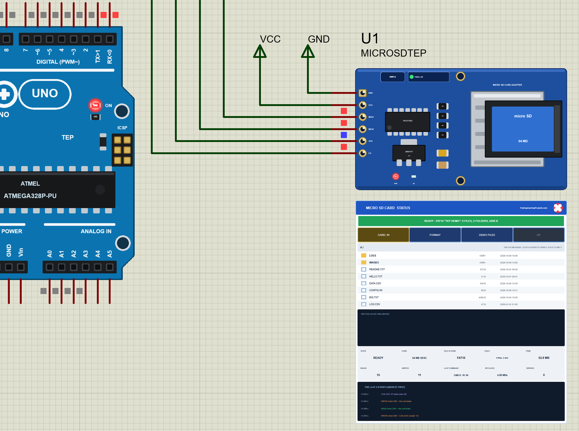
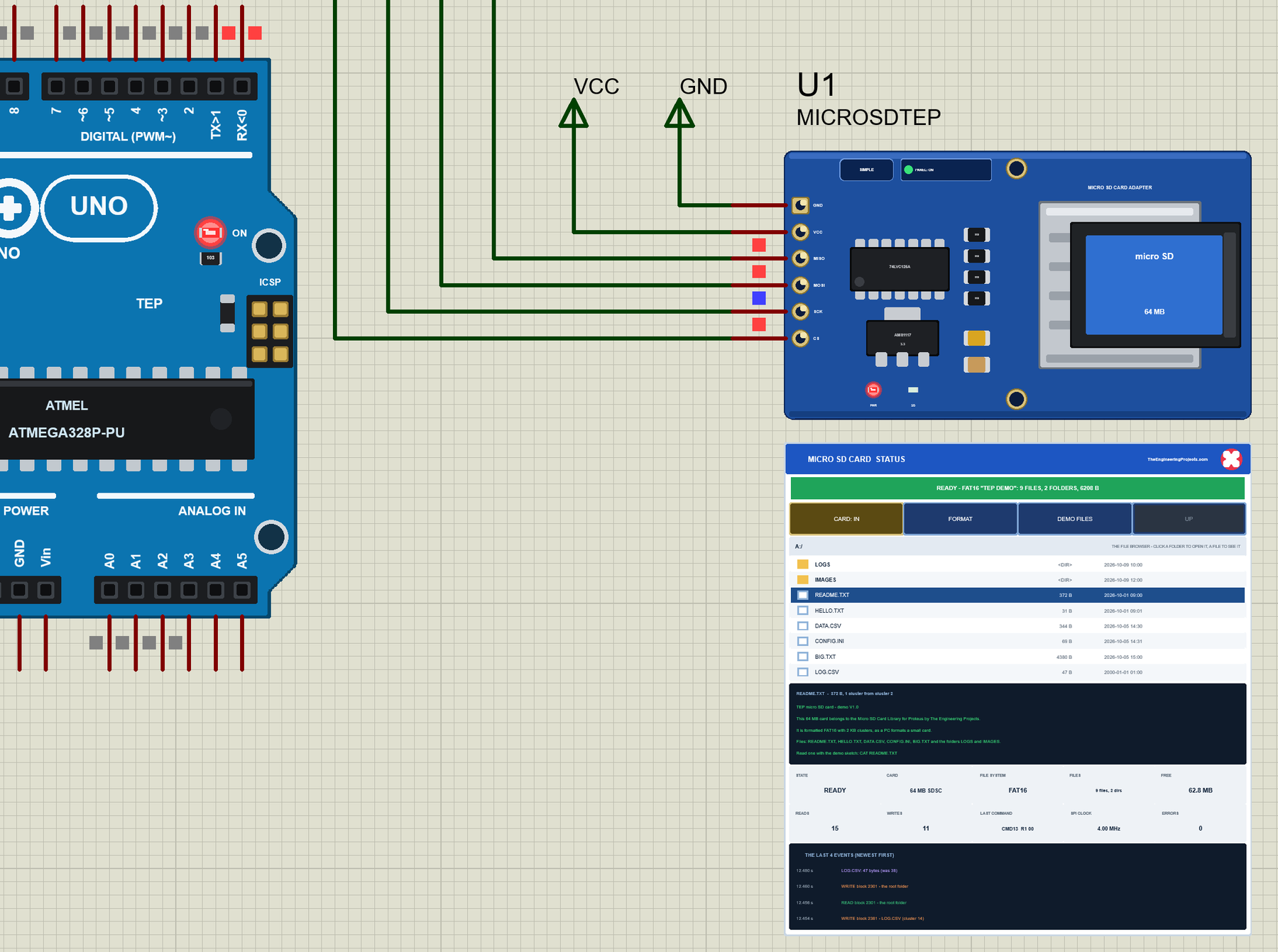
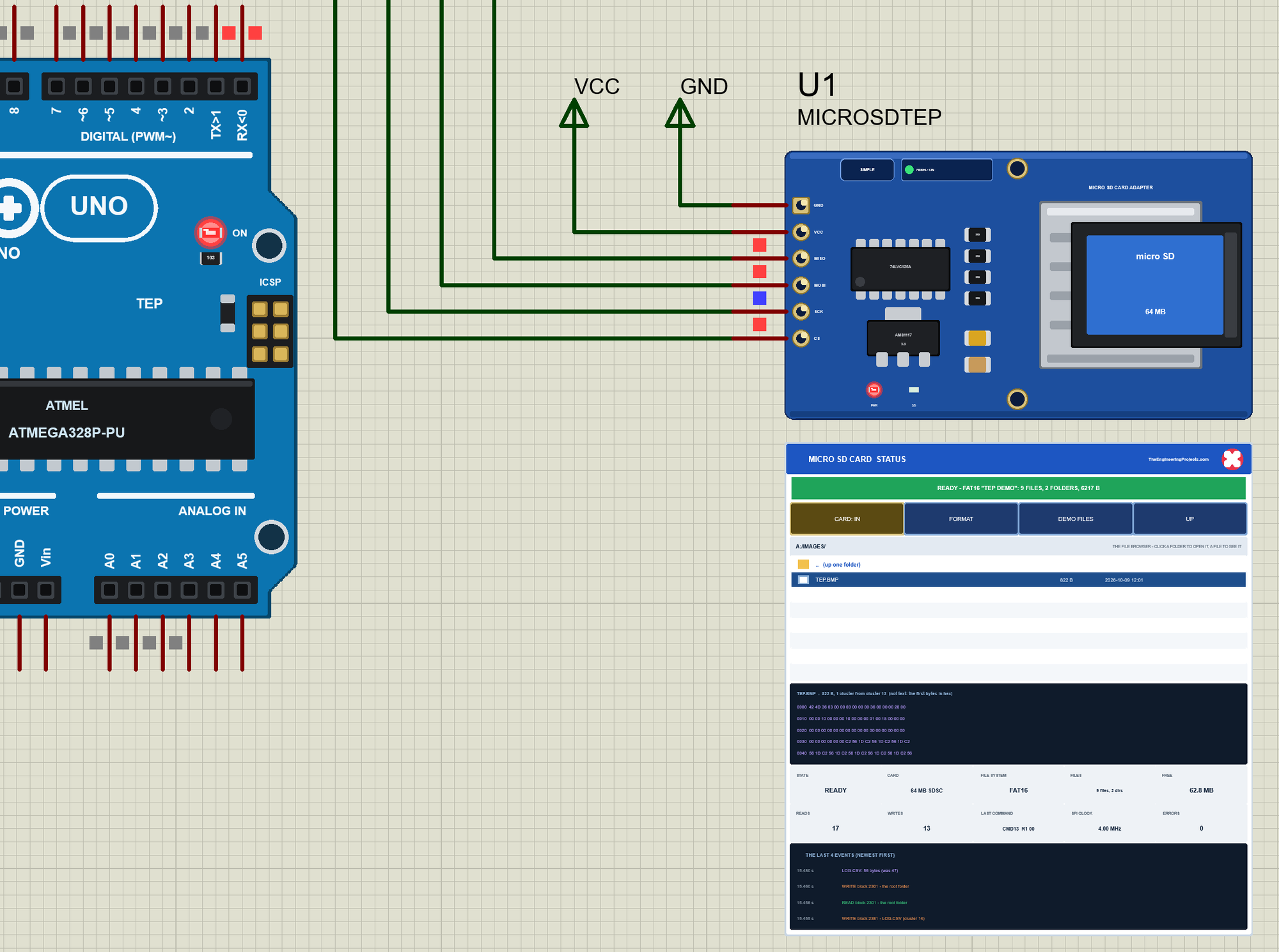
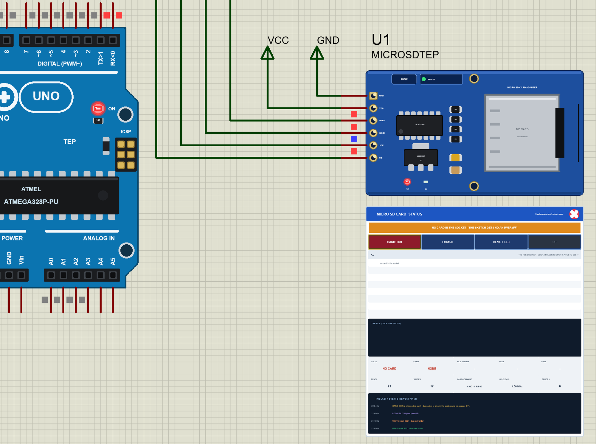
The Simple device adds the STATUS panel below the module. Its banner says what the card is doing: grey in SD mode, blue while it initialises, green when it is ready, amber for no card or no file system, red without power. Below it are the actions CARD: IN, FORMAT, DEMO FILES and UP, the path, the file browser with eight rows, the file you clicked, ten readouts and the last four events.
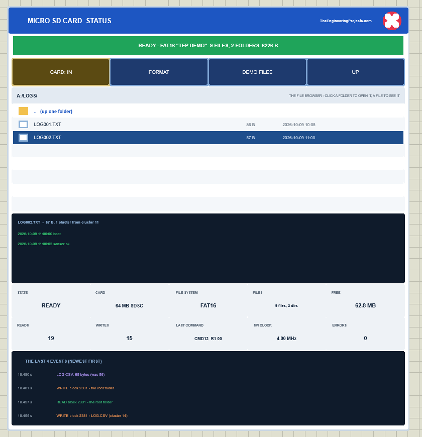
The readouts are the state, the card, the file system, the files and folders, the free space, the blocks read and written, the last command with its R1, the SPI clock and the errors. The red X closes the panel, and the PANEL button on the board opens it again. The Advance device keeps the schematic clean - only the module; the live data opens in a pop-up window at Run, and the OPEN PANEL button on the board brings the window back.
The CARD property sets the card at the start: DEMO (README.TXT, HELLO.TXT, DATA.CSV, CONFIG.INI, BIG.TXT and the folders LOGS and IMAGES), EMPTY (formatted, no files), RAW (never formatted - the card answers, but SD.begin() finds no file system) or NONE (an empty socket). The Simple device also has PANEL. Every run starts again from the properties: what the sketch wrote is gone after Stop.
The Demo Circuit
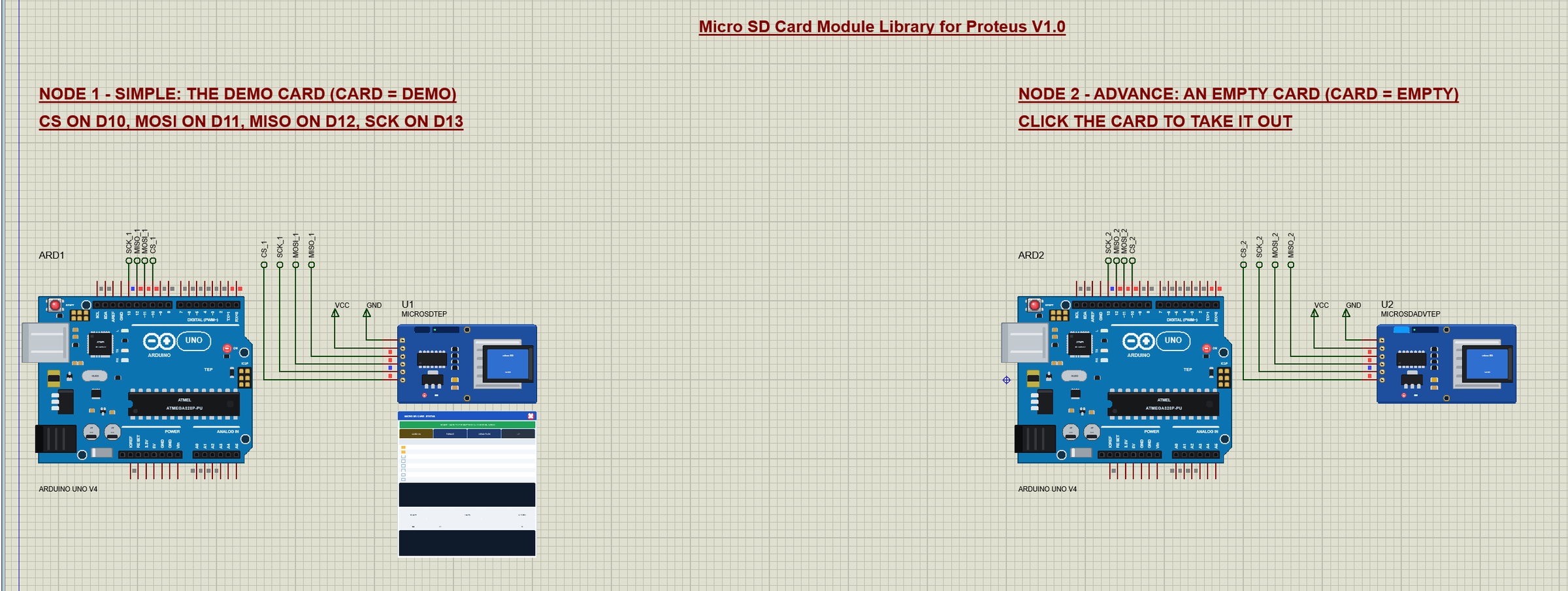
The demo project has two nodes, each an Arduino UNO V4.0 from our Arduino UNO Library for Proteus V4.0 with a micro SD card module. Node 1 has the demo card (CARD = DEMO) with files to read. Node 2 has an empty card (CARD = EMPTY) for the sketch to fill. Both UNOs run the same SD_Demo.hex.
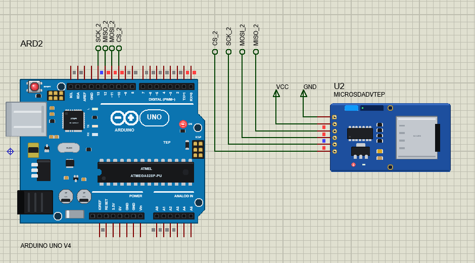
Wiring
| Module pin | Arduino UNO (the demo) | Notes |
|---|---|---|
| VCC | 5V | the AMS1117 makes 3.3 V |
| GND | GND | |
| MISO | D12 | the card to the Arduino |
| MOSI | D11 | the Arduino to the card |
| SCK | D13 | the SPI clock |
| CS | D10 | any free pin - SD.begin(pin) |
In the demo VCC and GND go to power terminals, and the four SPI lines run to labels (CS_1, MOSI_1, MISO_1, SCK_1 and so on) at the UNO's header. The serial monitor needs no wires at all, because it is built into the UNO V4.0. On an Arduino Mega the SPI pins are D50 (MISO), D51 (MOSI) and D52 (SCK).
The Arduino Code
The demo sketch uses the SD library 1.3.0 - it comes with the Arduino IDE. New to Arduino? Start with Arduino Tutorial for Beginners and Introduction to Arduino UNO. start() calls SD.begin() with the CS pin; the library initialises the card and mounts its first FAT partition:
bool start() {
  Serial.print(F("SD.begin("));
  Serial.print(CS_PIN);
  Serial.print(F("): "));
  cardOk = SD.begin(CS_PIN);
  if (cardOk) Serial.println(F("OK - the card is ready"));
  else Serial.println(F("FAILED - no card, no FAT file system or wrong wiring"));
  return cardOk;
}
dir() lists a folder. openNextFile() returns each entry in turn - its 8.3 name, whether it is a folder, and its size:
  for (File e = d.openNextFile(); e; e = d.openNextFile()) {
    Serial.print(F("  "));
    Serial.print(e.name());
    for (byte k = strlen(e.name()); k < 14; k++) Serial.print(' ');
    if (e.isDirectory()) { Serial.println(F("<DIR>")); folders++; }
    else { Serial.println(e.size()); files++; bytes += e.size(); }
    e.close();
  }
The data logger appends a line to LOG.CSV every 3 seconds. FILE_WRITE opens the file at its end and makes it if there is none, so a new file gets the header first:
void logLine() {
  File f = SD.open("LOG.CSV", FILE_WRITE);
  if (!f) {
    Serial.println(F("LOG.CSV: cannot open - is the card in? (INIT after putting it back)"));
    return;
  }
  if (f.size() == 0) f.println(F("line,time_ms"));   // a new file: the header first
  logLines++;
  unsigned long ms = millis();
  f.print(logLines);
  f.print(',');
  f.println(ms);
  bool failed = f.getWriteError();                   // the block could not be written: no card?
  unsigned long size = f.size();
close() is important: only then does the library write the last block and the file's new size to the folder entry. A sketch that never closes its file loses the data that was still in the library's 512-byte buffer.
The Commands
The loop reads a line from the serial monitor and hands it to command(): DIR [folder], CAT file, WRITE file text, DEL file, MKDIR folder, RMDIR folder, LOG n, INFO, INIT and HELP:
  else if (!strcmp(c, "DEL")) { Serial.print(arg); Serial.println(SD.remove(arg) ? F(" deleted") : F(": not deleted (no such file?)")); }
  else if (!strcmp(c, "MKDIR")) { Serial.print(arg); Serial.println(SD.mkdir(arg) ? F(": folder made") : F(": not made")); }
  else if (!strcmp(c, "RMDIR")) { Serial.print(arg); Serial.println(SD.rmdir(arg) ? F(": folder removed") : F(": not removed (not empty?)")); }
INFO reads the card and its volume directly with Sd2Card and SdVolume, as the CardInfo example of the SD library does:
  Serial.print(F("Volume: FAT"));
  Serial.print(volume.fatType());
  Serial.print(F(", "));
  Serial.print(volume.blocksPerCluster() * 512UL);
  Serial.print(F(" bytes a cluster, "));
  Serial.print(volume.clusterCount());
  Serial.print(F(" clusters = "));
  Serial.print(volume.clusterCount() * volume.blocksPerCluster() / 2048);
  Serial.println(F(" MB"));
One detail cost us a crash during testing: SdVolume keeps its block buffer in one shared place. When INFO mounts its own volume, the SD library's volume points to INFO's card object - which is gone when INFO returns. So INFO gives the buffer back with SD.end() and SD.begin():
void info() {
  Sd2Card card;                                    // the CardInfo example's way: the card and its volume, read directly
  SdVolume volume;
  cardInfo(card, volume);
  SD.end();                                        // SdVolume's block buffer is shared: give it back to SD
  cardOk = SD.begin(CS_PIN);
}
The HEX file is in the package, so you do not need the Arduino IDE to run the demo. To change the sketch, open it in the Arduino IDE and export the compiled binary, as in How to get the HEX file from Arduino. It needs 22,930 bytes of flash and 1,201 bytes of RAM - the SD library's 512-byte block buffer is the biggest part of it.
The Start: SD.begin() on Two Cards
At Run both UNOs start the sketch. ARD1's card is the demo card - SD.begin() works, and the root folder has five files and two folders:
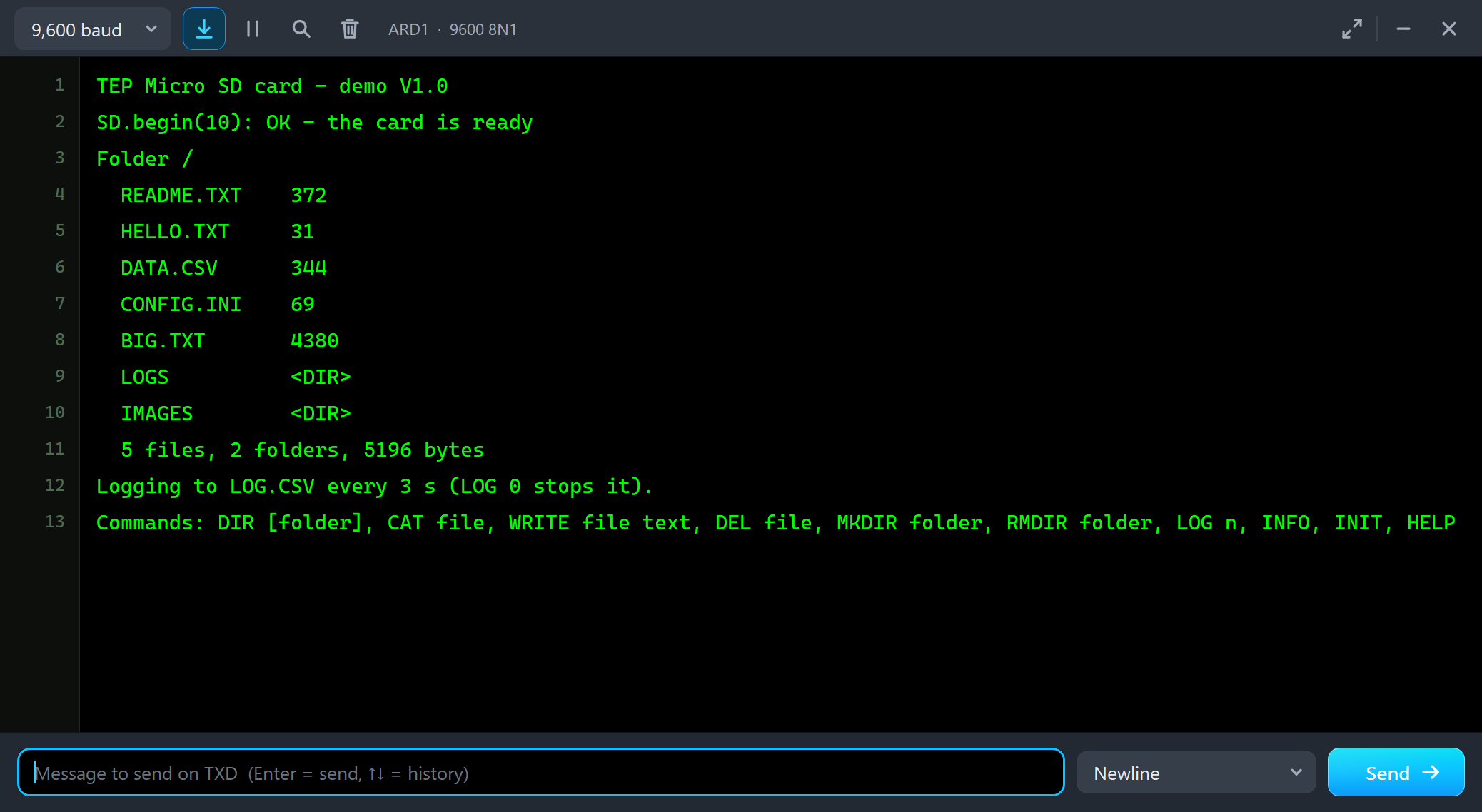
TEP Micro SD card - demo V1.0
SD.begin(10): OK - the card is ready
Folder /
  README.TXT    372
  HELLO.TXT     31
  DATA.CSV      344
  CONFIG.INI    69
  BIG.TXT       4380
  LOGS          <DIR>
  IMAGES        <DIR>
  5 files, 2 folders, 5196 bytes
Logging to LOG.CSV every 3 s (LOG 0 stops it).
Commands: DIR [folder], CAT file, WRITE file text, DEL file, MKDIR folder, RMDIR folder, LOG n, INFO, INIT, HELP
ARD2's card is empty - formatted, but without a single file:
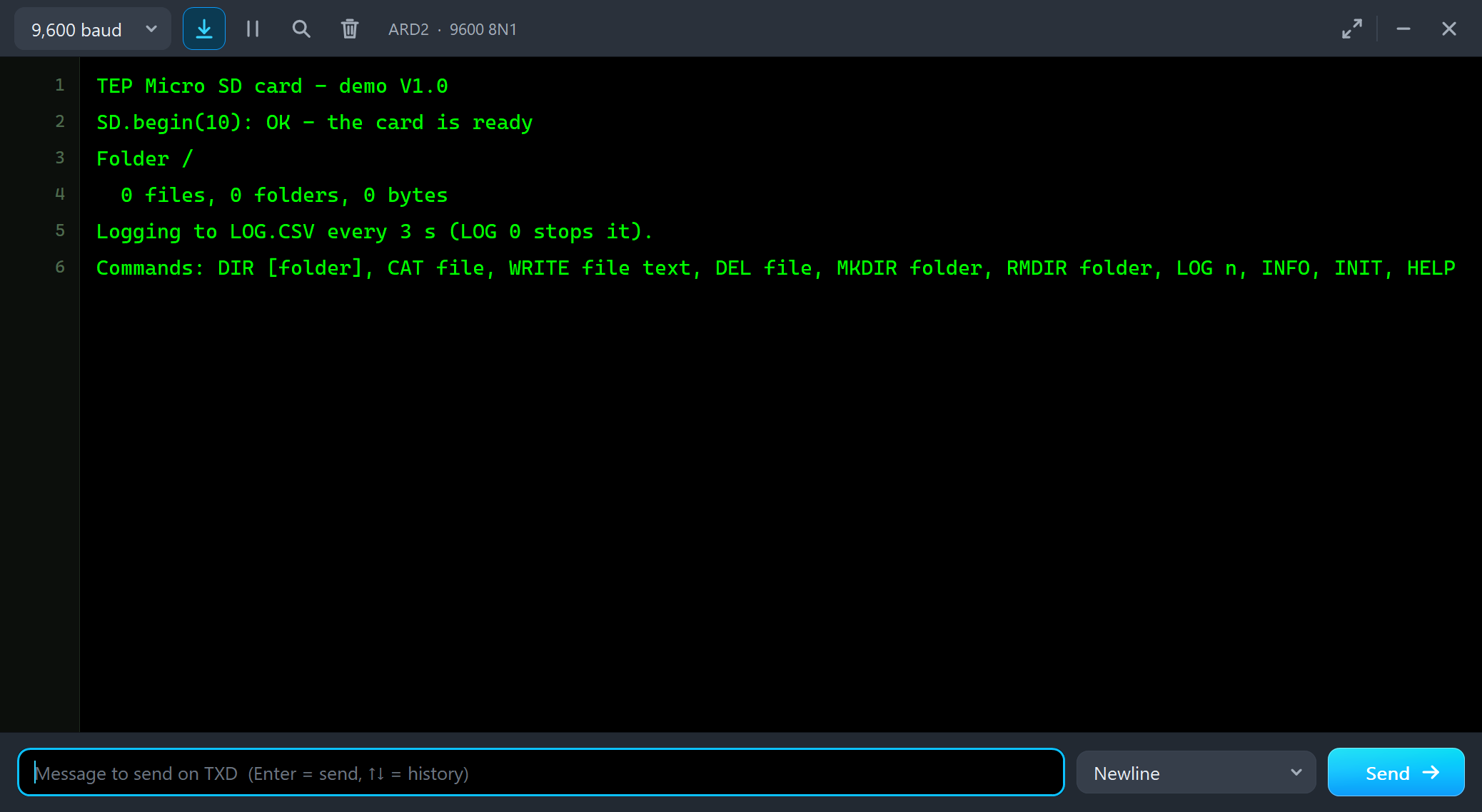
TEP Micro SD card - demo V1.0
SD.begin(10): OK - the card is ready
Folder /
  0 files, 0 folders, 0 bytes
Logging to LOG.CSV every 3 s (LOG 0 stops it).
Commands: DIR [folder], CAT file, WRITE file text, DEL file, MKDIR folder, RMDIR folder, LOG n, INFO, INIT, HELP
U2 opens its own window, Micro SD Card Module, with the look of our TEP Serial Monitor Advance for Proteus. It has three tabs, Card, Event log and Tests, plus Settings and Help behind the gear and question mark icons:
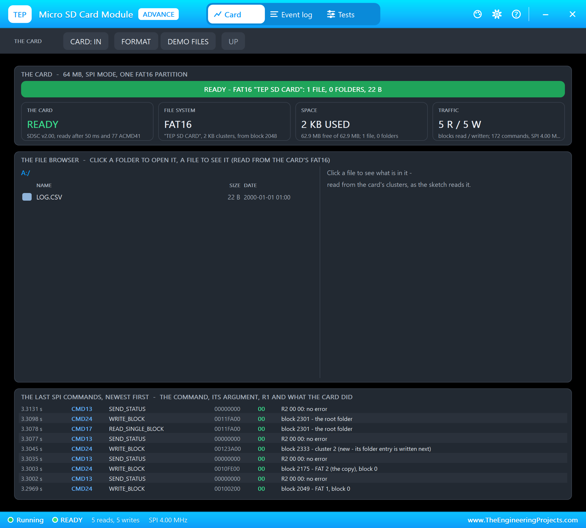
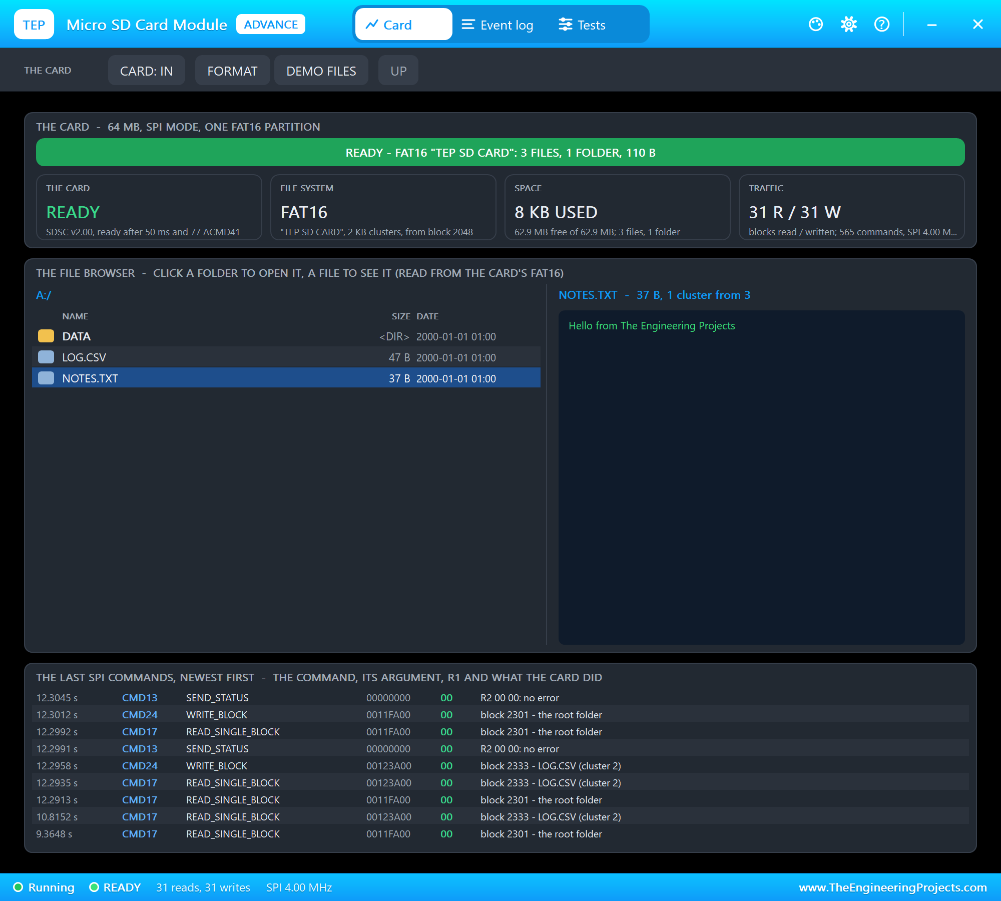
The Card page shows the banner, four tiles - the card, the file system, the space and the traffic -, the file browser with the file you clicked beside it, and the last SPI commands, each with its argument, its R1 and what the card did: which block, and which file the block belongs to.
Writing Files on the Empty Card
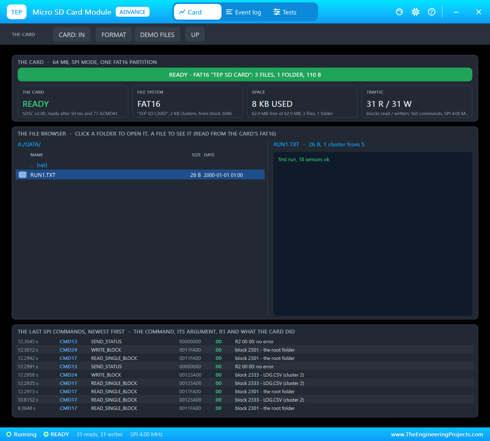
We typed INFO, WRITE NOTES.TXT Hello from The Engineering Projects, MKDIR DATA, WRITE DATA/RUN1.TXT first run, 18 sensors ok, DIR and CAT LOG.CSV in ARD2's monitor:
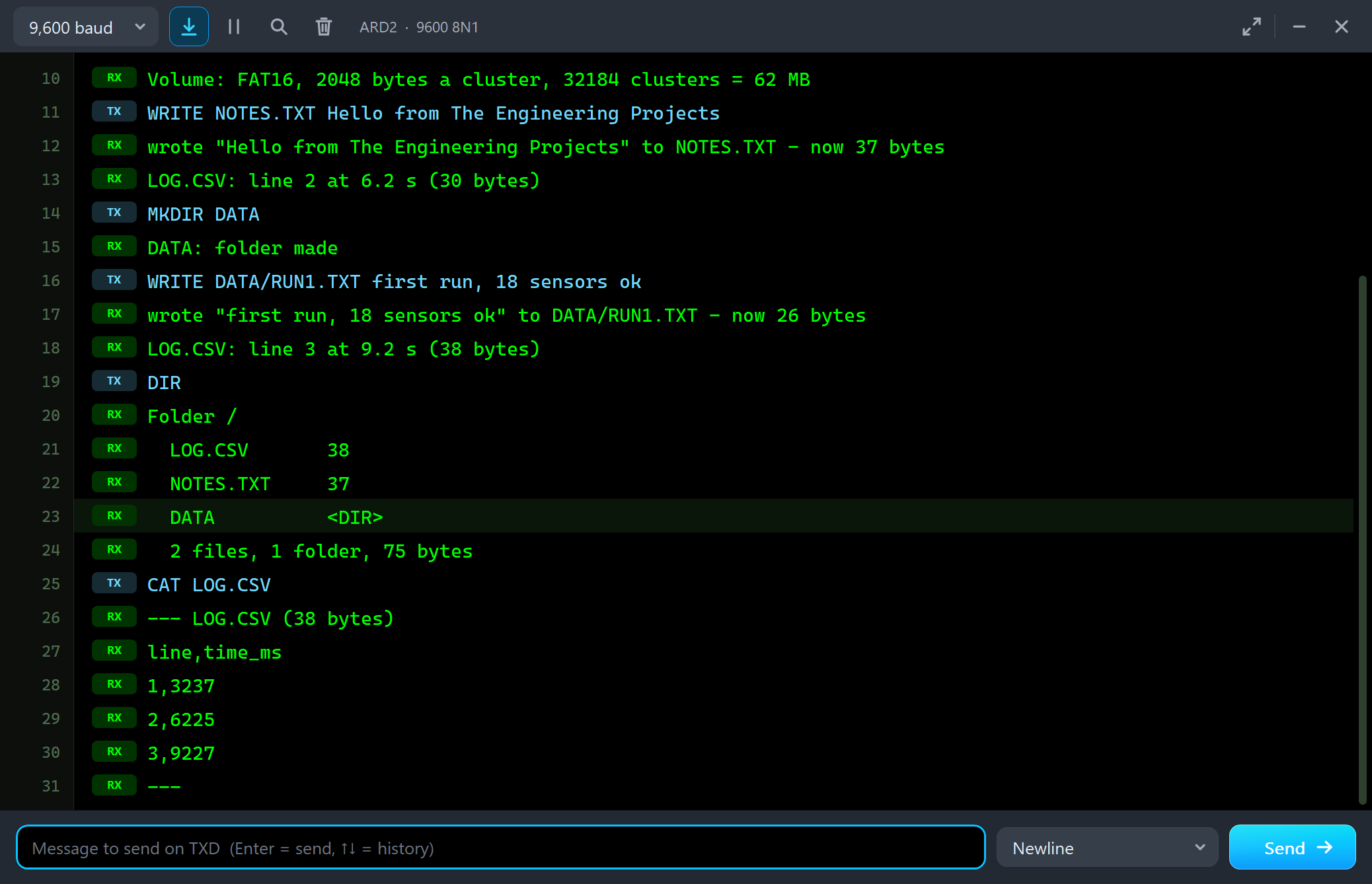
Volume: FAT16, 2048 bytes a cluster, 32184 clusters = 62 MB
WRITE NOTES.TXT Hello from The Engineering Projects
wrote "Hello from The Engineering Projects" to NOTES.TXT - now 37 bytes
LOG.CSV: line 2 at 6.2 s (30 bytes)
MKDIR DATA
DATA: folder made
WRITE DATA/RUN1.TXT first run, 18 sensors ok
wrote "first run, 18 sensors ok" to DATA/RUN1.TXT - now 26 bytes
LOG.CSV: line 3 at 9.2 s (38 bytes)
DIR
Folder /
  LOG.CSV       38
  NOTES.TXT     37
  DATA          <DIR>
  2 files, 1 folder, 75 bytes
CAT LOG.CSV
--- LOG.CSV (38 bytes)
line,time_ms
1,3237
2,6225
3,9227
---
INFO shows the card as the SD library sees it: an SD2 card (version 2.00, standard capacity), 64 MB, FAT16 with 2048-byte clusters. The files the sketch made are dated 2000-01-01 01:00 - the SD library's default, because the sketch has no clock. A clock module such as our DS3231 RTC Module Library for Proteus and SdFile::dateTimeCallback() give them the real time. The pop-up at that moment:
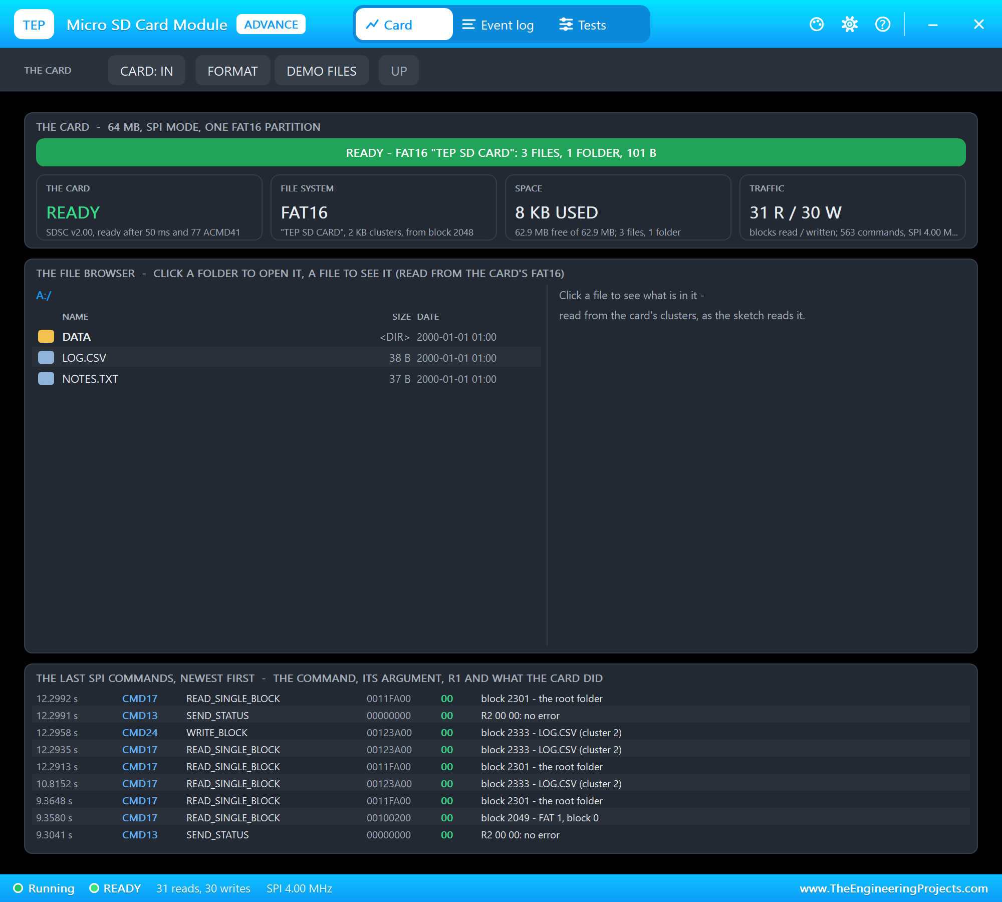
We clicked NOTES.TXT in the browser - the model reads it from the card's clusters, as the sketch would:
And the folder DATA, then the file in it:
Pulling the Card Out
Then we clicked CARD: IN on the pop-up's toolbar - the card came out of the socket:
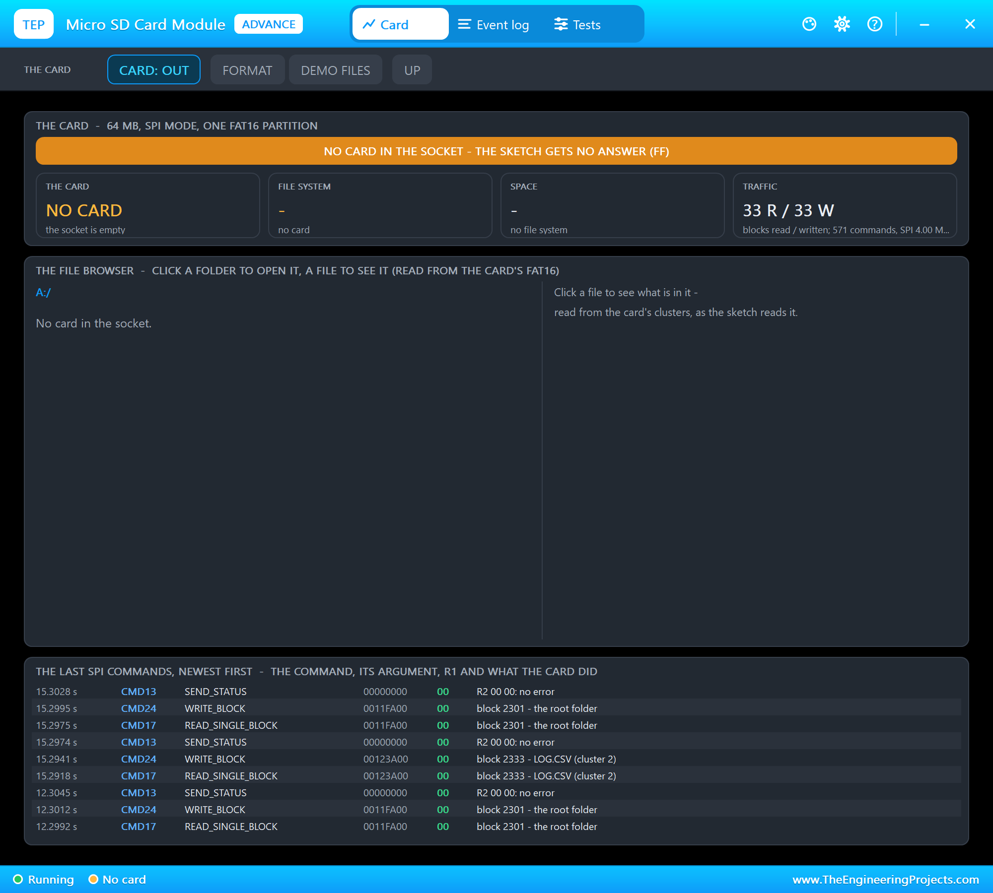
The next time the logger wanted to write, it got no answer - the socket was empty:
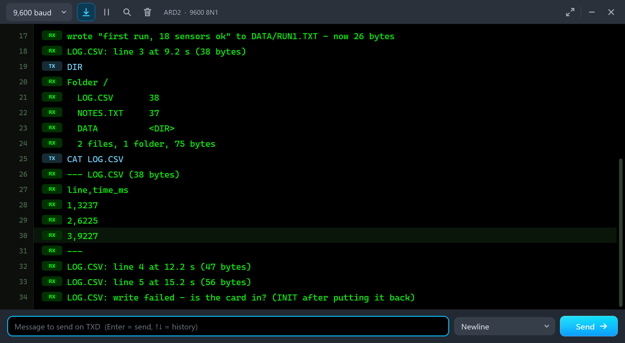
LOG.CSV: line 4 at 12.2 s (47 bytes)
LOG.CSV: line 5 at 15.2 s (56 bytes)
LOG.CSV: write failed - is the card in? (INIT after putting it back)
We clicked CARD: OUT to put it back. A card that comes back is in SD mode again, just like a new one, so the sketch must start it again: INIT calls SD.end() and SD.begin(). Then we deleted NOTES.TXT, tried to remove DATA while RUN1.TXT was still in it, deleted RUN1.TXT and removed the folder:
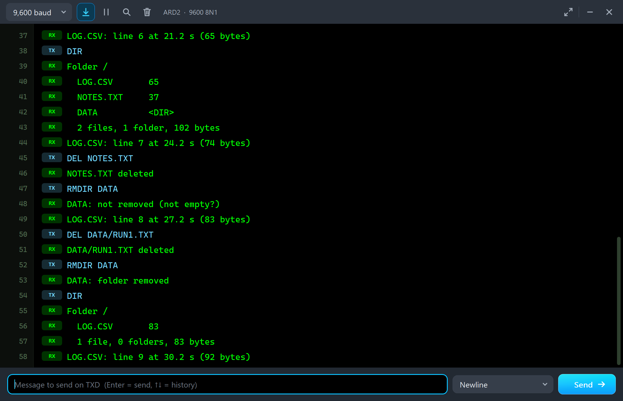
LOG.CSV: line 6 at 21.2 s (65 bytes)
DIR
Folder /
  LOG.CSV       65
  NOTES.TXT     37
  DATA          <DIR>
  2 files, 1 folder, 102 bytes
LOG.CSV: line 7 at 24.2 s (74 bytes)
DEL NOTES.TXT
NOTES.TXT deleted
RMDIR DATA
DATA: not removed (not empty?)
LOG.CSV: line 8 at 27.2 s (83 bytes)
DEL DATA/RUN1.TXT
DATA/RUN1.TXT deleted
RMDIR DATA
DATA: folder removed
DIR
Folder /
  LOG.CSV       83
  1 file, 0 folders, 83 bytes
LOG.CSV: line 9 at 30.2 s (92 bytes)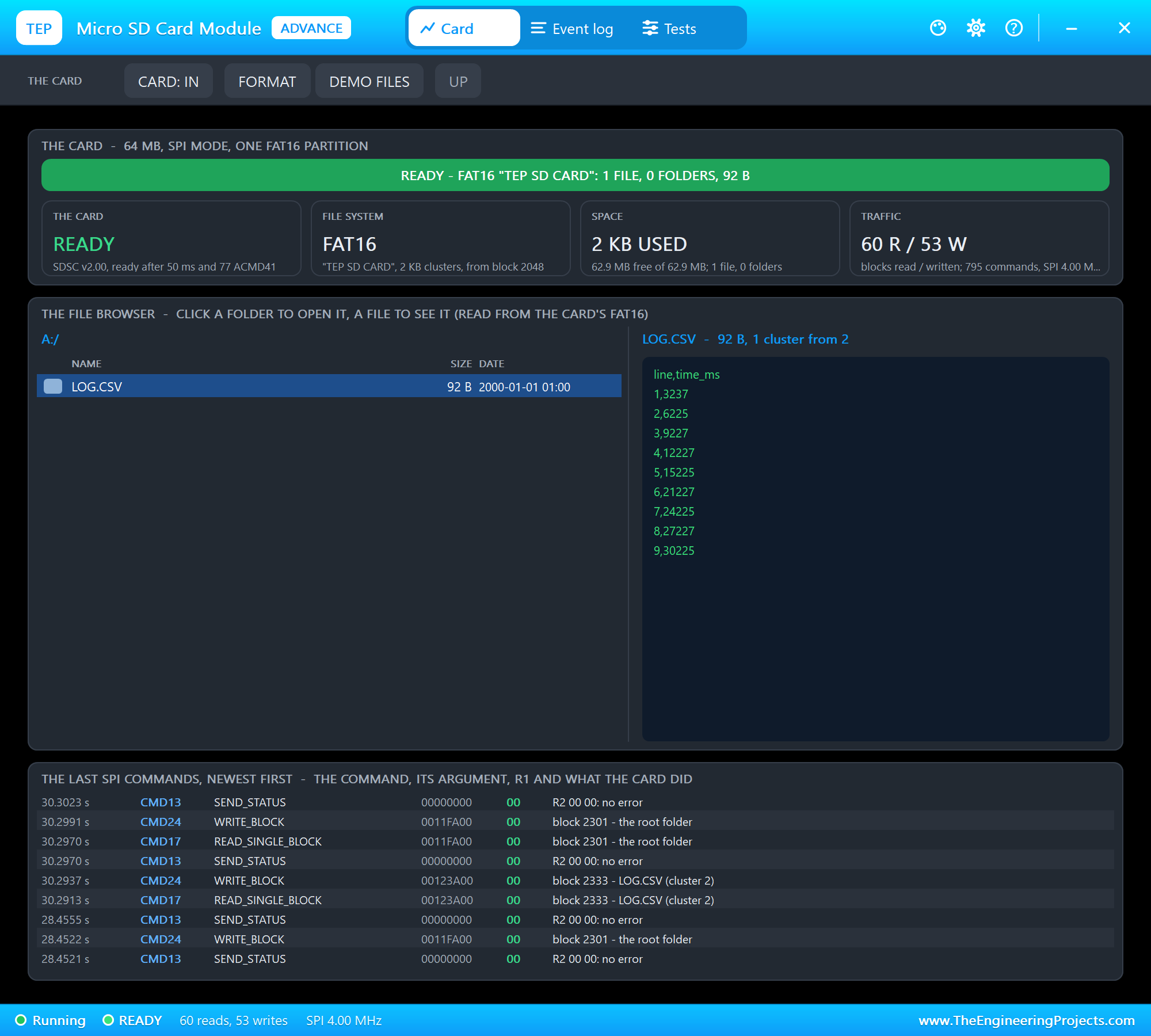
Look at the SPI commands of one logger line: the file's block 2333 read and written, the status (CMD13) after the write, then the root folder (block 2301) read and written again with the file's new size. One line in a CSV file costs several blocks - that is why a data logger should keep its file open and write many lines before it closes it.
Reading the Demo Card
On node 1 we typed CAT README.TXT, DIR LOGS, CAT LOGS/LOG002.TXT and INFO:
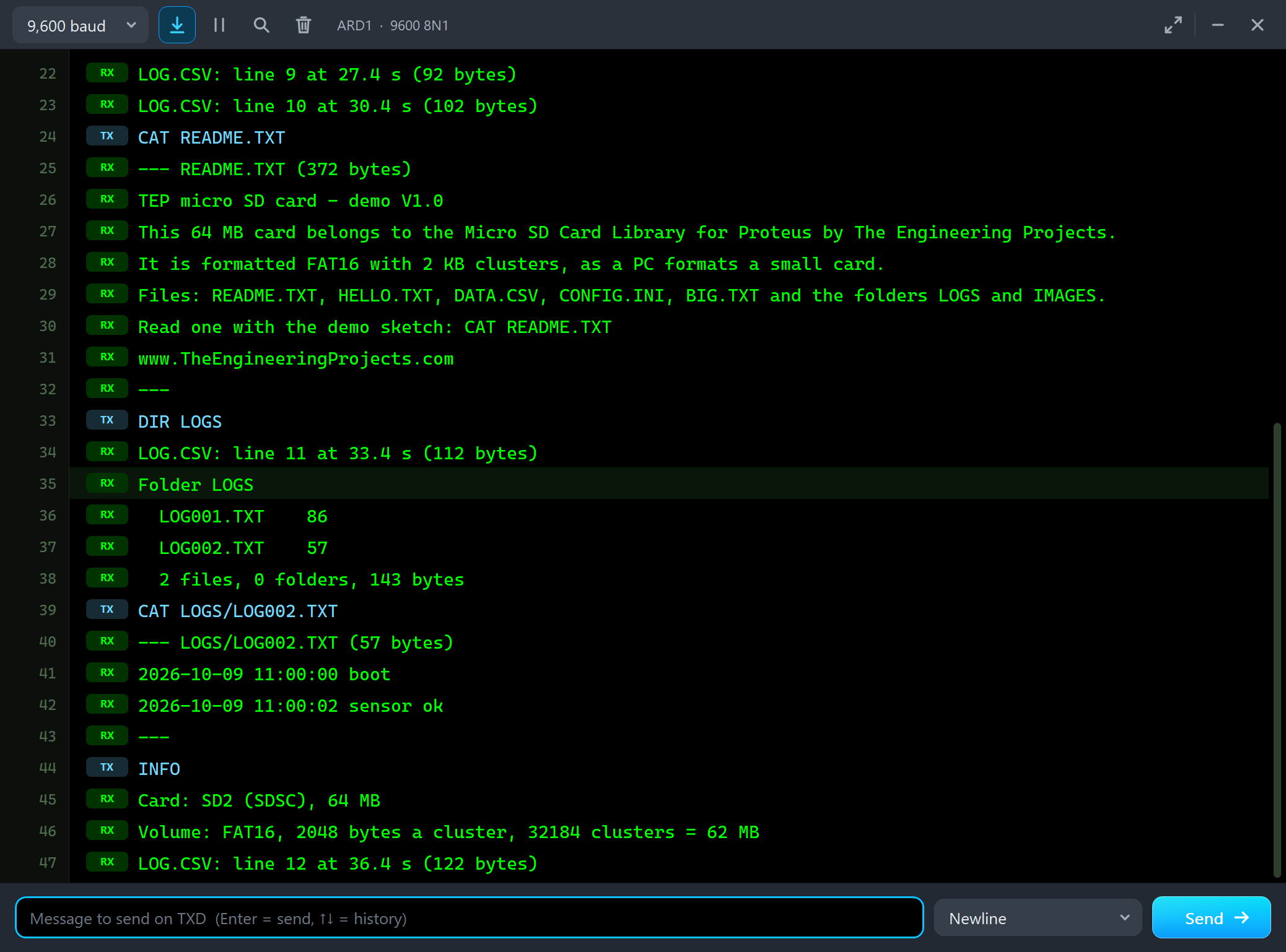
CAT README.TXT
--- README.TXT (372 bytes)
TEP micro SD card - demo V1.0
This 64 MB card belongs to the Micro SD Card Library for Proteus by The Engineering Projects.
It is formatted FAT16 with 2 KB clusters, as a PC formats a small card.
Files: README.TXT, HELLO.TXT, DATA.CSV, CONFIG.INI, BIG.TXT and the folders LOGS and IMAGES.
Read one with the demo sketch: CAT README.TXT
www.TheEngineeringProjects.com
---
DIR LOGS
LOG.CSV: line 11 at 33.4 s (112 bytes)
Folder LOGS
  LOG001.TXT    86
  LOG002.TXT    57
  2 files, 0 folders, 143 bytes
CAT LOGS/LOG002.TXT
--- LOGS/LOG002.TXT (57 bytes)
2026-10-09 11:00:00 boot
2026-10-09 11:00:02 sensor ok
---
INFO
Card: SD2 (SDSC), 64 MB
Volume: FAT16, 2048 bytes a cluster, 32184 clusters = 62 MB
The File Browser with the Mouse
Back to node 1, the Simple part. We clicked README.TXT on its STATUS panel - its first lines appeared below the browser, as in the first picture of this post. Then the folder IMAGES and the bitmap in it. A file that is not text shows its first bytes in hex:
UP went back to the root, and LOGS and LOG002.TXT gave the close-up of the panel above. Then we clicked the card itself, and it came out of the socket:
CARD: OUT on the panel put it back, and INIT in ARD1's monitor started it again. Every click on the card, a folder or a file was read back from the model; two clicks that landed on the thin line between two rows did nothing - click a row in its middle.
DEMO FILES: a Card Swap
FORMAT and DEMO FILES change the whole card while the simulation runs - like taking the card to a PC and back. We clicked DEMO FILES on U2 and typed INIT and DIR; then we clicked README.TXT:
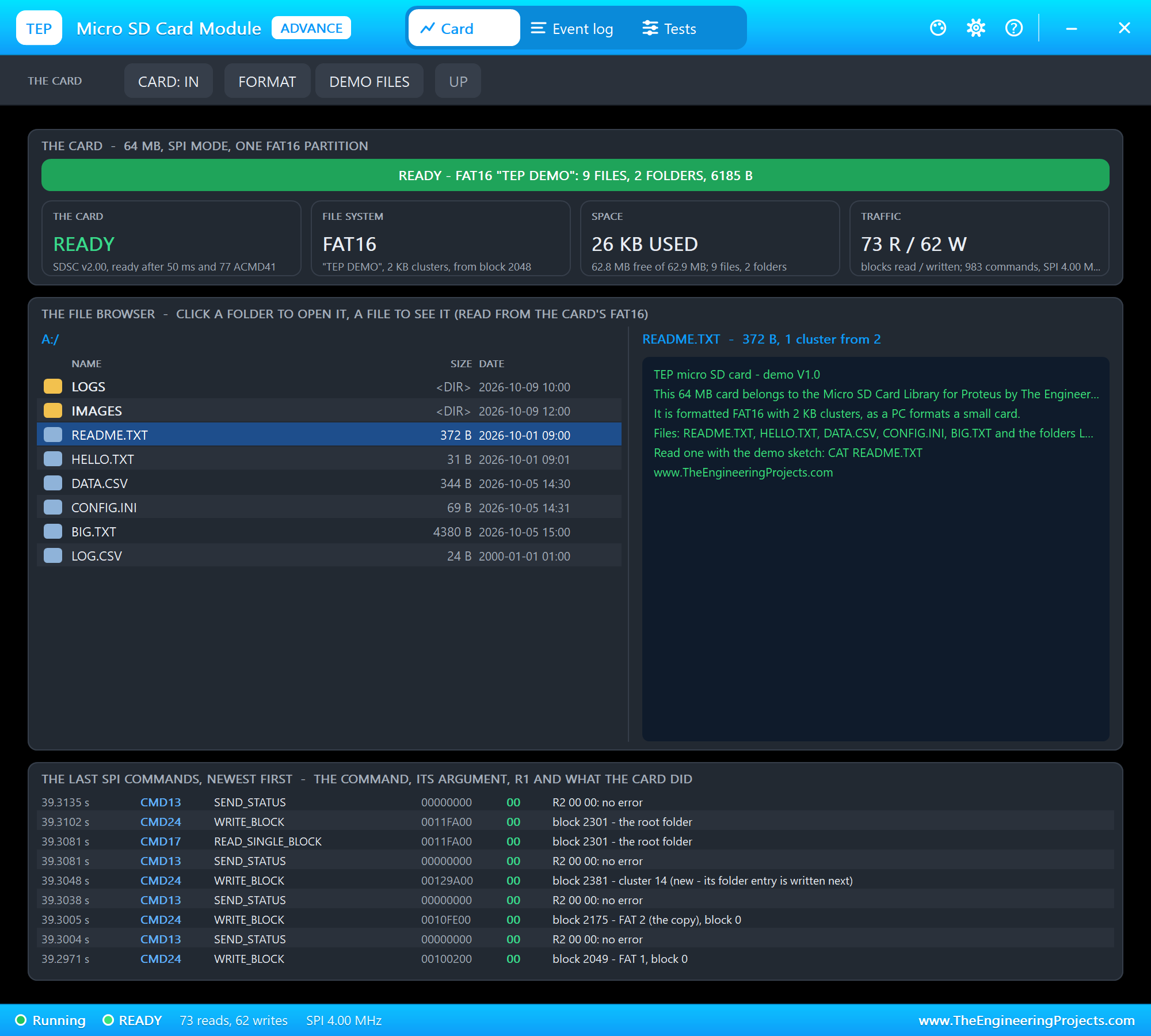
Why INIT? Because a card that comes back starts in SD mode, so the sketch must initialise it again. The SD library also keeps one block of the old card in its buffer; if the card answered right away, the library could write that old block over the new file system. In our first tests it did exactly that - LOG.CSV landed in README.TXT's cluster. Now the card gives no answer until SD.begin(), as a real card that was swapped.
The Test Tools
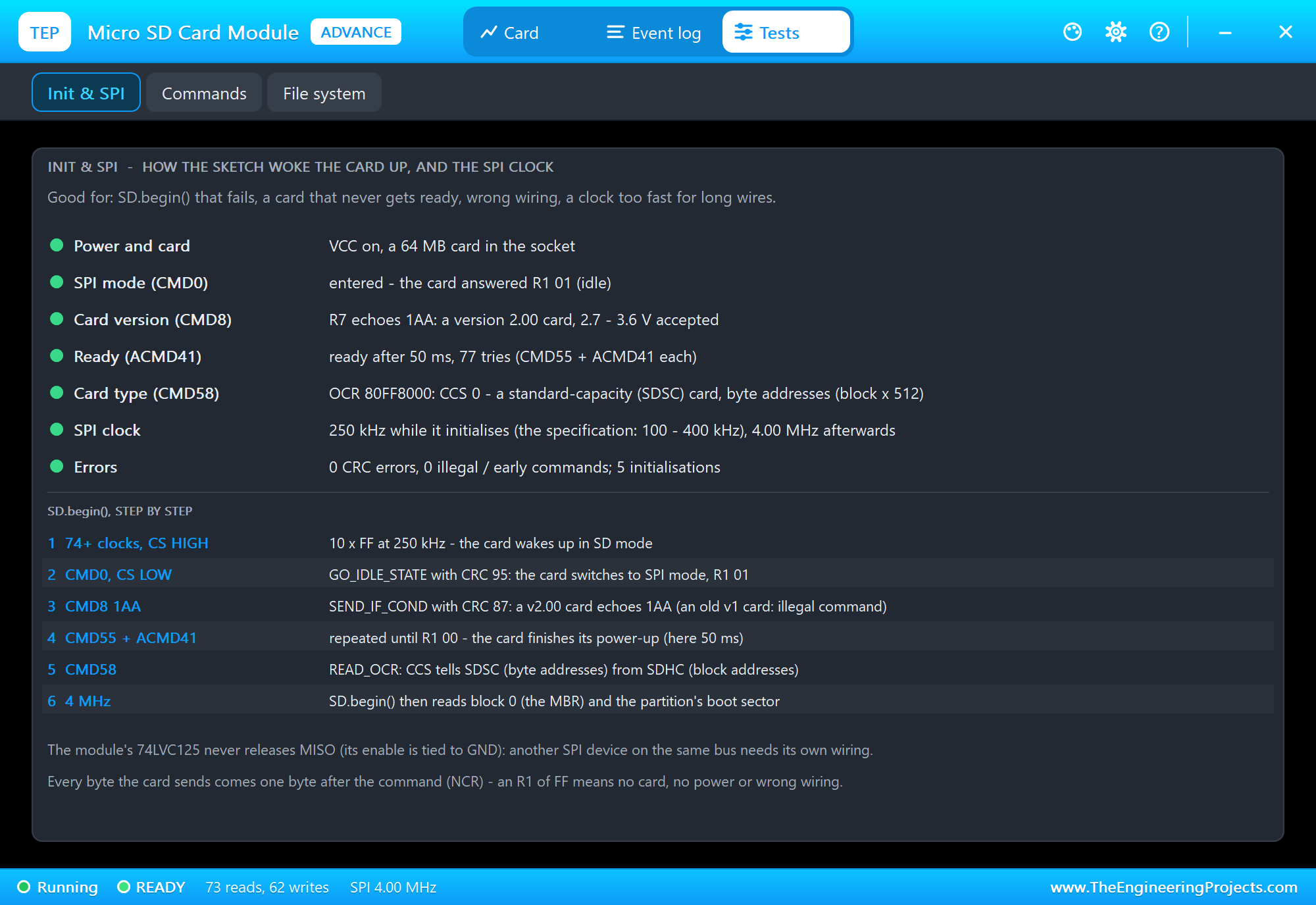
Init and SPI is good for an SD.begin() that fails, a card that never gets ready, wrong wiring or a clock that is too fast. It shows each step of the start-up with a verdict - power and the card, SPI mode, the card version, how long ACMD41 took and how many tries, the card type - and the SPI clock: 250 kHz while the card initialises, 4 MHz after.
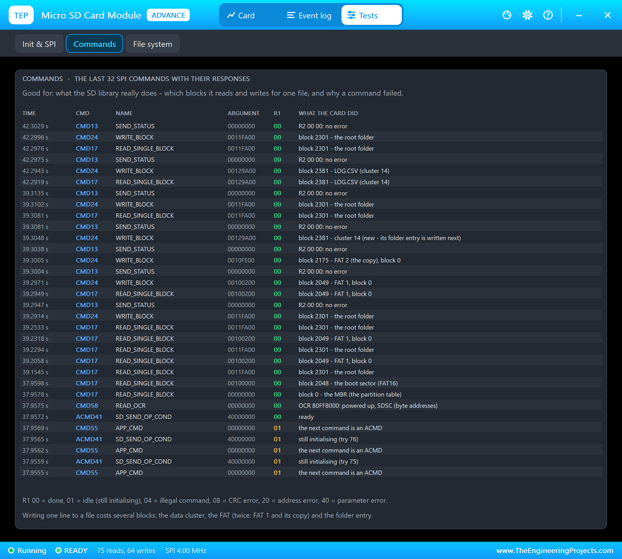
Commands lists the last 32 SPI commands: the time, the command and its name, the argument, R1 and what the card did. It is good for seeing what the SD library really does - which blocks one file costs - and why a command failed.
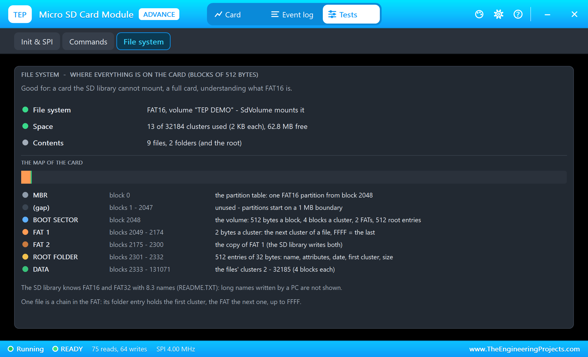
File system is good for a card the SD library cannot mount, a full card, or just to understand FAT16: the volume, the space, the files and folders, and the map of the card from the MBR to the data area.
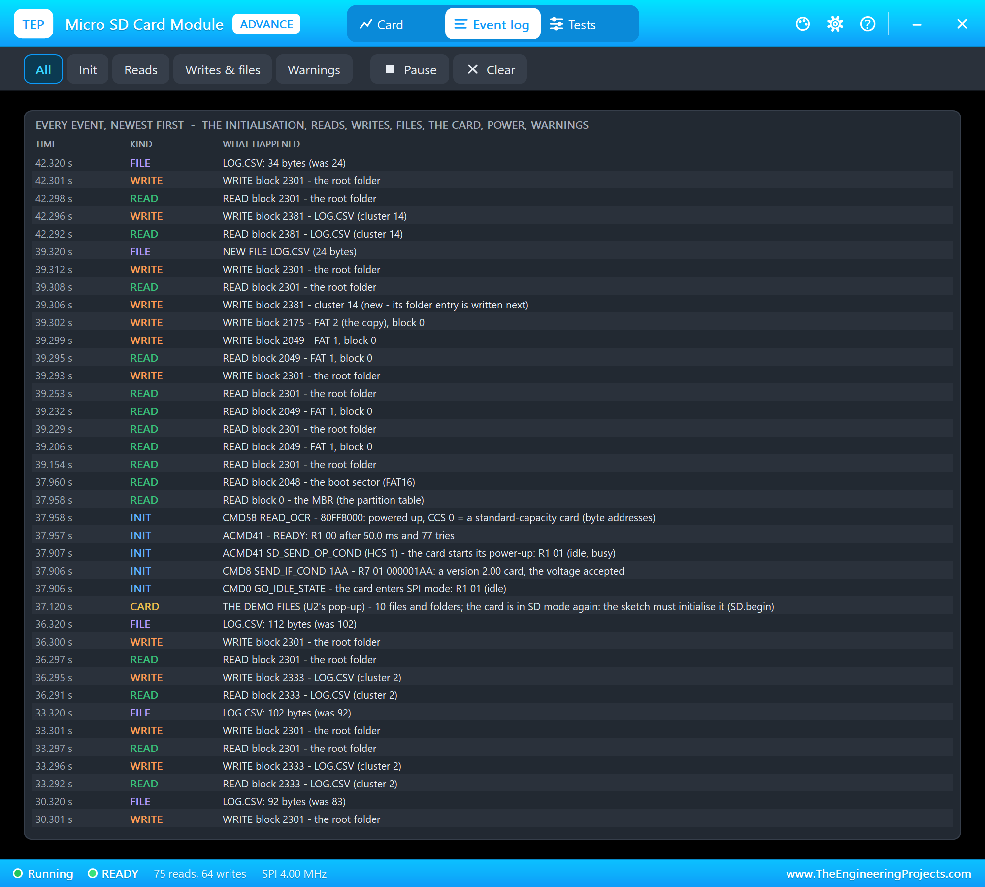
The Event log lists everything that happened, newest first: the initialisation, the blocks read and written with the file they belong to, new and deleted files and folders, the card out and in, power and warnings. Filter it, pause it, or clear it.
The Simulation Log
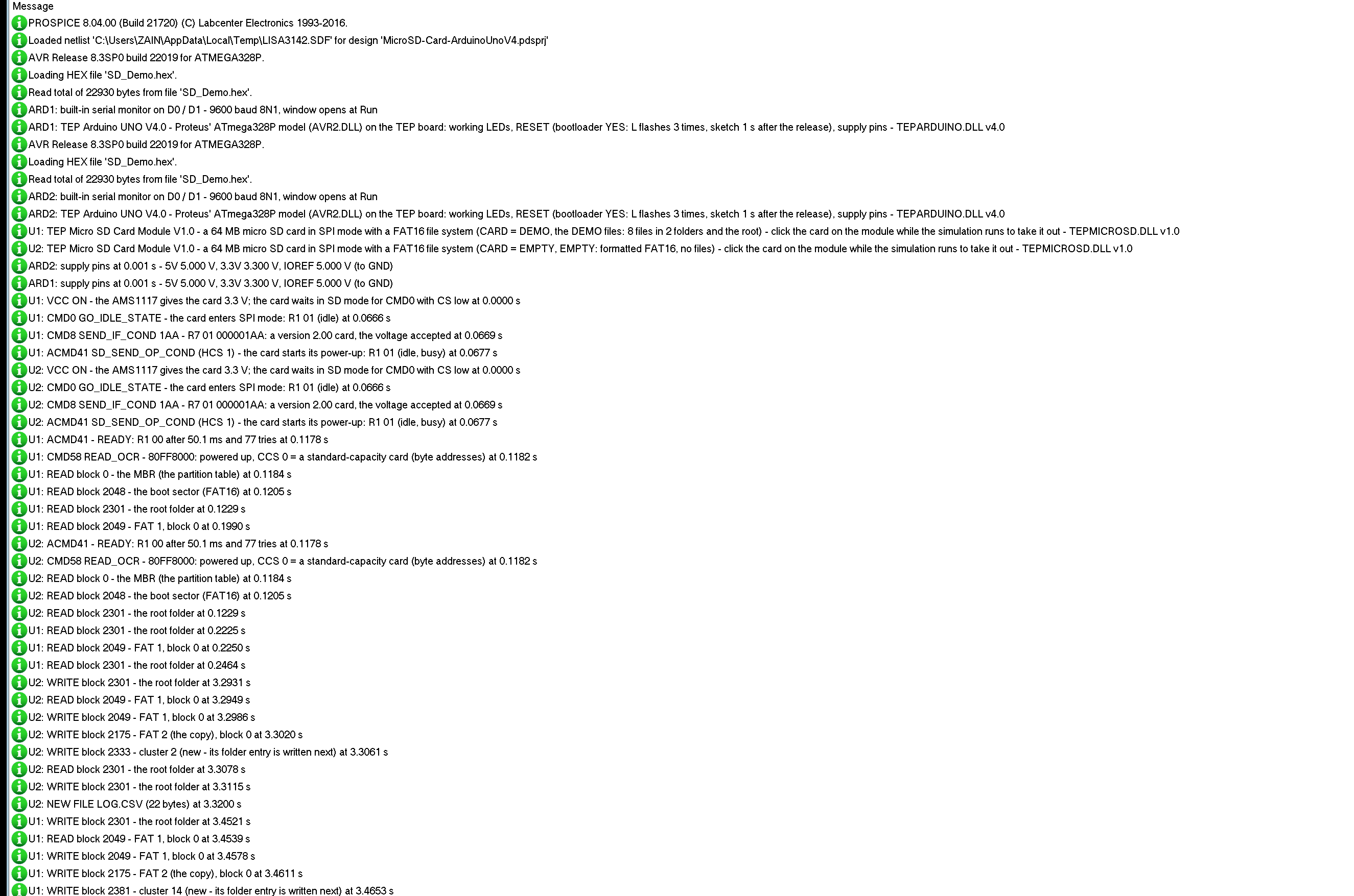
The parts also write to the simulation log of Proteus, with the exact simulation time. These lines show the start of node 1 and the first file on node 2:
U1: VCC ON - the AMS1117 gives the card 3.3 V; the card waits in SD mode for CMD0 with CS low at 0.0000 s
U1: CMD0 GO_IDLE_STATE - the card enters SPI mode: R1 01 (idle) at 0.0666 s
U1: CMD8 SEND_IF_COND 1AA - R7 01 000001AA: a version 2.00 card, the voltage accepted at 0.0669 s
U1: ACMD41 SD_SEND_OP_COND (HCS 1) - the card starts its power-up: R1 01 (idle, busy) at 0.0677 s
U1: ACMD41 - READY: R1 00 after 50.1 ms and 77 tries at 0.1178 s
U1: CMD58 READ_OCR - 80FF8000: powered up, CCS 0 = a standard-capacity card (byte addresses) at 0.1182 s
U1: READ block 0 - the MBR (the partition table) at 0.1184 s
U1: READ block 2048 - the boot sector (FAT16) at 0.1205 s
U1: READ block 2301 - the root folder at 0.1229 s
U1: READ block 2049 - FAT 1, block 0 at 0.1990 s
U2: WRITE block 2301 - the root folder at 3.2931 s
U2: READ block 2049 - FAT 1, block 0 at 3.2949 s
U2: WRITE block 2049 - FAT 1, block 0 at 3.2986 s
U2: WRITE block 2175 - FAT 2 (the copy), block 0 at 3.3020 s
U2: WRITE block 2333 - cluster 2 (new - its folder entry is written next) at 3.3061 s
U2: READ block 2301 - the root folder at 3.3078 s
U2: WRITE block 2301 - the root folder at 3.3115 s
U2: NEW FILE LOG.CSV (22 bytes) at 3.3200 s
How the Model Works
The model watches the pins: when CS goes LOW it puts the first bit of its next byte on MISO; on every rising edge of SCK it reads one bit of MOSI, on every falling edge it puts its next bit on MISO. After eight bits the byte goes to the card: six bytes make a command, the card queues its answer - one FF, then R1 and the rest -, and the next byte out comes from that queue. The time between the first and the eighth rising edge gives the SPI clock. The card keeps only the blocks that were ever written; every other block reads 00. A FAT16 reader walks the same blocks for the file browser and the tools, and 5 ms after the last write it compares the files with the ones before - that is how the log knows about a new file or folder.
Troubleshooting
- "SD.begin(10): FAILED": no card (click the socket), CARD = RAW (FORMAT on the panel or toolbar), MISO and MOSI swapped, CS on another pin than the sketch's, VCC missing (the PWR LED), or the part has no model - TEPMICROSD.DLL in MODELS and beside the project.
- Every command answers FF: the card is out, unpowered, or still in SD mode because CMD0 never came with CS LOW - Init and SPI shows which.
- After the card was out, or after FORMAT or DEMO FILES: the card is in SD mode again - the sketch must call SD.begin() again (INIT in the demo).
- A file is missing: the SD library shows 8.3 names only, and a folder needs DIR folder.
- The simulation is slow while the sketch reads: each byte is 16 SCK edges - 4 MHz SPI is a lot of edges for Proteus.
- No part or no monitor: TEPMICROSD.DLL or TEPARDUINO.DLL is missing; a closed monitor opens again with a click on the UNO's USB port.
Things to Know Before Using a Real Micro SD Card Module
- MISO: on most of these modules the 74LVC125A drives MISO all the time, even while CS is HIGH. Another SPI device on the same bus may need a resistor or its own pins.
- The card: format it FAT16 or FAT32 (cards up to 32 GB); exFAT cards (64 GB and more) do not work with the SD library.
- Names: the SD library uses 8.3 names (README.TXT); long file names written by a PC are not shown.
- Power: feed the module from 5V - the AMS1117 needs more than 3.3 V at its input.
- Close your files: data that is still in the library's buffer is lost when the power goes.
Limitations of the Simulation
- Not modelled: SD mode (the 4-bit bus), SDHC and SDXC cards (block addresses), the CRC7 of commands after CMD8, write protection, the card's current, the 25 MHz limit (any clock works), timing errors inside a byte.
- The model's own choices: ACMD41 finishes 50 ms after the first one, a block is programmed in 1.5 ms, an erase takes 0.5 ms a block, blocks never written read 00, and what the sketch writes lasts until Stop.
- The badge, the LEDs, the clickable card, the panel button and the panels are TEP additions.
- The model is our own implementation written from the SD Physical Layer Simplified Specification and the FAT file system. This library is not made or endorsed by the SD Association, SD-3C, Microchip / Atmel, Arduino, SparkFun or Labcenter.
- Licences: the HEX file contains the SD library 1.3.0 (GNU GPL v3 - its source is on GitHub, the link is in the README) and the Arduino AVR core 1.8.6 with LGPL-licensed code - the source link is in the README.
- Tested in Proteus 8.5 in October 2026 (the demo as shipped on two Arduino UNO V4.0 boards with their built-in monitors: SD.begin on the demo and the empty card, the logger, INFO, WRITE, MKDIR, DIR, CAT, DEL and RMDIR, the card out and in with INIT, DEMO FILES and the three tools on the Advance part; the browser and the card with the mouse on the Simple one; 46.4 s of simulation took 163 s with the pop-up and both monitors open, about 0.28 x real time). Proteus 7 is not supported.
So, that was all about the Micro SD Card Module Library for Proteus V1.0. I hope SPI mode, the start-up of the card and FAT16 are clear now, and that your data logger writes its first file in Proteus before you solder anything. If you use the Micro SD Card Module Library for Proteus in a project, please share it in the comments or in our forum, and if you have any questions, ask in the comments and I will help you out. Till the next tutorial, take care and have fun!