Hello friends, I hope you are doing well. This is the seventeenth tutorial in our series on how to create a Proteus library. In the previous tutorial, How to Design a User Interactive Library in Proteus, we added a Push Button Module to our library and used it to switch the red lamp of our Traffic Light Module. Both parts were built entirely from Proteus's own primitives. Today, we write a model in C++ instead. Our topic is how to create a Proteus simulation model DLL in C++.
A model DLL can do things a drawn model cannot. Our Traffic Light Module still has the LOGIC property from the eighth tutorial, the one that says whether a lamp lights on a HIGH or on a LOW pin, and in the fifteenth tutorial we left it unused because a schematic model cannot honour it. A few lines of C++ can. We will look at what a VSM model DLL is, write one for our module, compile it with Visual Studio, link it to a new version of the part and test it in a simulation.
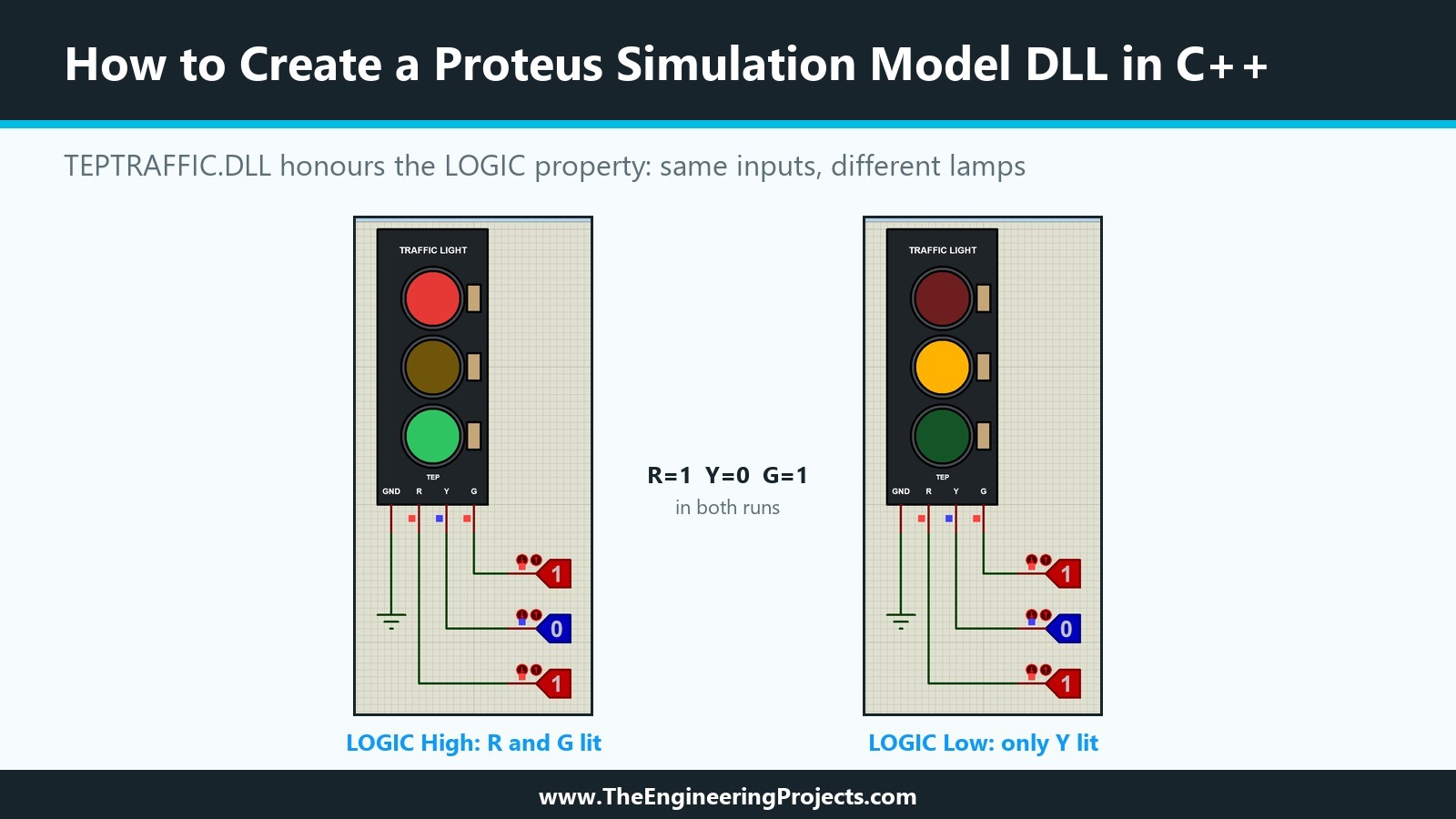
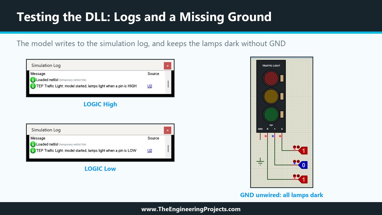
Everything shown here was done in Proteus 8.5 Professional and Visual Studio 2026 Community on our PC. The picture below shows the result: the same module with the same inputs, R and G high and Y low, once with LOGIC set to High and once set to Low. The lamps follow the property, and the only thing that changed is one value in the part's properties.
What Is a Proteus Simulation Model DLL?
In the twelfth tutorial, we met the four kinds of simulation model the Proteus help describes: primitive models built into the simulator, schematic models, SPICE models and VSM models. The help calls VSM models primitive models that are implemented in external DLLs instead of inside PROSPICE, and says that they let you simulate a device in the programming language of your choice, although C++ is generally the easiest.
PRIMITIVE and MODDLL
Because the schematic editor and the simulator treat a VSM model as a primitive, the part carries a PRIMITIVE property, and a MODDLL property names the DLL that holds the code. The help's example is the 8052 microcontroller, with PRIMITIVE=DIGITAL,8052 and MODDLL=MCS8051, and it adds that one DLL can implement several primitive types: MCS8051.DLL serves a number of 8051 variants. Our own TEP libraries use the same trick; the RFM95 and SX1262 parts, for example, both point to TEPSX1278.DLL.
Animation from the Same DLL
The help also says that a VSM model can implement the animation of a part, so that its electrical and graphical behaviour are combined. That is the Link to DLL option in the Active Component Properties of Make Device, which we left unticked in the fifteenth and sixteenth tutorials. With it ticked, the same DLL that simulates the part also draws it.
Where Proteus Looks for the DLL
According to the troubleshooting section of the help, a model DLL must be in the current folder or in the module path, which is the Simulation Model and Module Folders setting in System Settings. On our installation, that is the MODELS folder, where our MDF files from the fourteenth and sixteenth tutorials already sit. The help lists Model DLL not found as the error for a DLL outside these folders.
What You Need Before You Start
A VSM model is ordinary C++ code, but it needs three things from outside.
The VSM SDK Header
The interfaces between Proteus and a model are C++ classes declared in Labcenter's header file vsm.hpp, part of the VSM SDK. The SDK is not installed with Proteus 8.5: the VSM SDK entry of the installed help only asks you to contact Labcenter, sign an NDA and have a valid Update Service Contract. We built our model against the header from Labcenter's SDK; we describe our own code here, not the contents of the header, so you need your own copy from Labcenter to compile it.
A 32-Bit C++ Compiler
Proteus 8.5 is a 32-bit program. We checked the PE header of PDS.EXE: its machine type is x86, and so is every model DLL in the MODELS folder, Labcenter's HGPOT.DLL as well as our own TEP DLLs. A 32-bit program cannot load a 64-bit DLL, so the model must be compiled for x86. We used Visual Studio 2026 Community with its C++ build tools, whose vcvars32.bat sets up the 32-bit compiler.
A Part to Link It To
We kept the Traffic Light Module of the earlier tutorials as it is, because its schematic model measures the lamp currents that our ammeters show. The DLL version becomes a second part in the same library, TRAFFICLIGHTVSMTEP, with the same drawing and the same state symbols.
How a VSM Model Talks to Proteus
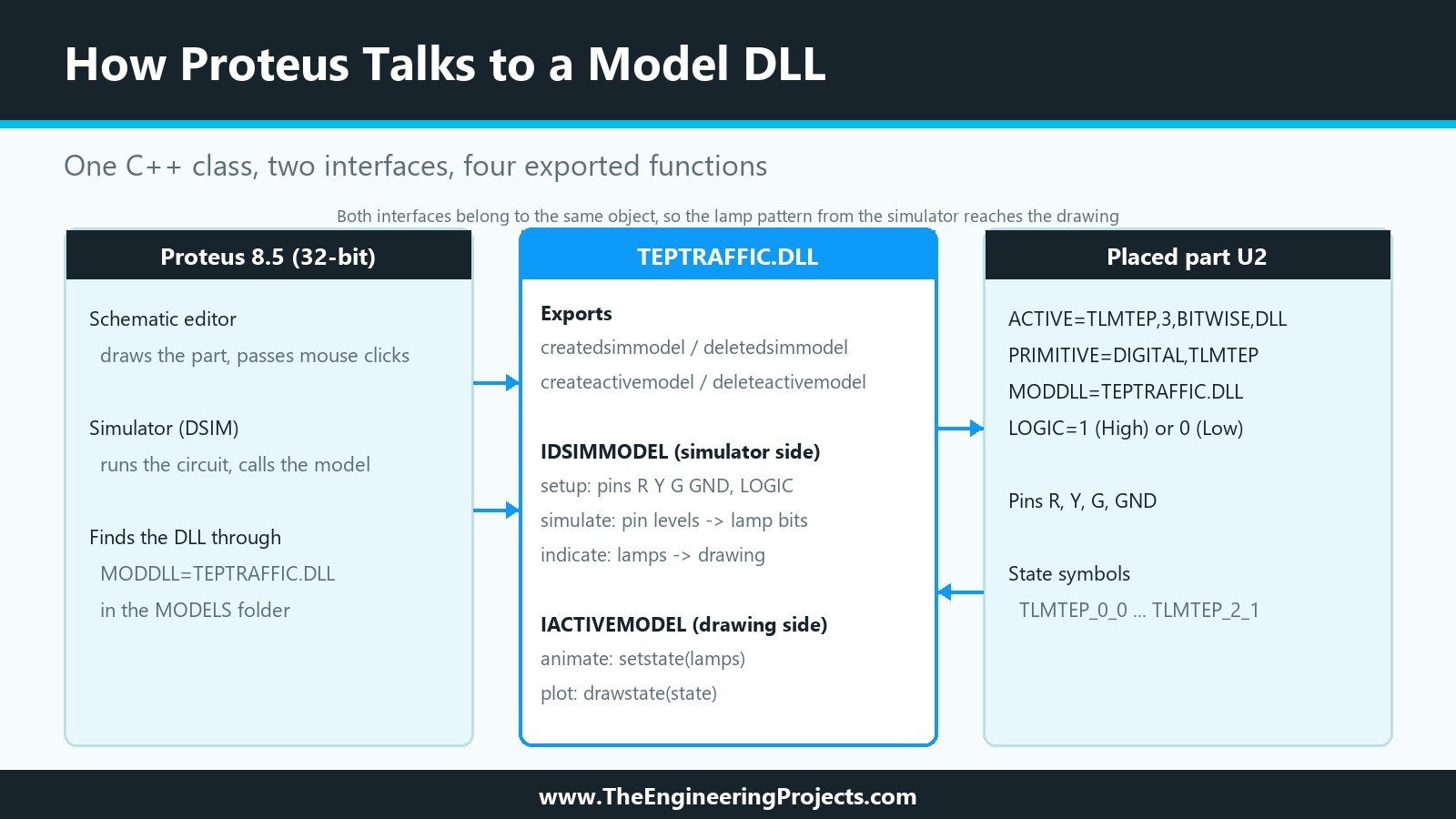
Our model implements two interfaces from the SDK in one C++ class, the same pattern our TEP libraries use. The diagram shows who calls what.
The Simulator Side: IDSIMMODEL
IDSIMMODEL is the interface of a digital model. The simulator calls setup once at the start, with an IINSTANCE object that gives access to the pins and properties of the placed part, and then calls simulate whenever one of the part's input pins changes. A model reads a pin with istate and tests the result with ishigh and islow. Its indicate function is how the simulator side passes data to the animation.
The Drawing Side: IACTIVEMODEL
IACTIVEMODEL is the interface of an animated part. The schematic editor calls initialize with an ICOMPONENT object, which offers drawing services and the properties of the part, calls plot to draw the part, animate when new data arrives from indicate, and actuate when the user clicks the part. getdsimmodel connects the two sides: our class returns itself.
The Four Exported Functions
Proteus creates and deletes model objects through four functions that the DLL exports by name: createdsimmodel and deletedsimmodel for the simulator side, and createactivemodel and deleteactivemodel for the drawing side. Each create function receives the primitive name and a licence server object, and our code asks the licence server to authorise the model before it creates the object, as our TEP models do.
How to Create a Proteus Simulation Model DLL in C++: Step by Step
We built the DLL version of our module in five steps: the source, the build, the installation, the part and the test circuit.
Step 1: Write the Model
Here is the complete source of our model, TrafficLightModel.cpp:
// TEP Traffic Light Module - Proteus VSM model DLL (TEPTRAFFIC.DLL)
// The Engineering Projects - www.TheEngineeringProjects.com
//
// Pins  : R, Y, G (digital inputs), GND (optional; the lamps stay dark unless it is LOW)
// LOGIC : 1 = a lamp lights when its pin is HIGH, 0 = when its pin is LOW
// Lamps : bit 0 = red, bit 1 = yellow, bit 2 = green, shown with the TLMTEP state symbols

#include <cstddef>   // NULL, which vsm.hpp uses
#include "vsm.hpp"

class TrafficLightModel : public IDSIMMODEL, public IACTIVEMODEL {
    ICOMPONENT* component_ = nullptr;   // drawing side, in the schematic editor
    IINSTANCE* instance_ = nullptr;     // simulator side
    IDSIMPIN *red_ = nullptr, *yellow_ = nullptr, *green_ = nullptr, *gnd_ = nullptr;
    bool activeHigh_ = true;
    int lamps_ = 0;       // lamp pattern computed by the simulator side
    int reported_ = -1;   // last pattern passed on to the drawing side

    static bool activeHighFrom(const char* text) {
        if (!text || !*text) return true;
        const char c = text[0];
        return !(c == '0' || c == 'L' || c == 'l' || c == 'F' || c == 'f');
    }
    bool lit(IDSIMPIN* pin) const {
        const STATE s = pin->istate();
        return activeHigh_ ? ishigh(s) : islow(s);
    }

public:
    // IACTIVEMODEL: drawing the part
    VOID initialize(ICOMPONENT* component) override { component_ = component; }
    ISPICEMODEL* getspicemodel(CHAR*) override { return nullptr; }
    IDSIMMODEL* getdsimmodel(CHAR*) override { return this; }
    VOID plot(ACTIVESTATE state) override { component_->drawstate(state); }
    VOID animate(INT, ACTIVEDATA* data) override {
        if (data && data->type == ADT_INTEGER) component_->setstate(data->intval);
    }
    BOOL actuate(WORD, INT, INT, DWORD) override { return FALSE; }

    // IDSIMMODEL: simulating the part
    INT isdigital(CHAR*) override { return TRUE; }
    VOID setup(IINSTANCE* instance, IDSIMCKT*) override {
        instance_ = instance;
        red_ = instance->getdsimpin((CHAR*)"R", TRUE);
        yellow_ = instance->getdsimpin((CHAR*)"Y", TRUE);
        green_ = instance->getdsimpin((CHAR*)"G", TRUE);
        gnd_ = instance->getdsimpin((CHAR*)"GND", FALSE);
        activeHigh_ = activeHighFrom(instance->getstrval((CHAR*)"LOGIC", (CHAR*)"1"));
        lamps_ = 0;
        reported_ = -1;
        instance->log((CHAR*)"TEP Traffic Light: model started, lamps light when a pin is %s",
                      activeHigh_ ? "HIGH" : "LOW");
    }
    VOID runctrl(RUNMODES) override {}
    VOID actuate(REALTIME, ACTIVESTATE) override {}
    BOOL indicate(REALTIME, ACTIVEDATA* data) override {
        if (lamps_ == reported_) return FALSE;
        reported_ = lamps_;
        data->type = ADT_INTEGER;
        data->intval = lamps_;
        return TRUE;
    }
    VOID simulate(ABSTIME, DSIMMODES) override {
        const bool grounded = !gnd_ || islow(gnd_->istate());
        int lamps = 0;
        if (grounded) {
            if (lit(red_)) lamps |= 1;
            if (lit(yellow_)) lamps |= 2;
            if (lit(green_)) lamps |= 4;
        }
        lamps_ = lamps;
    }
    VOID callback(ABSTIME, EVENTID) override {}
};

// Proteus calls these four functions to create and delete the model objects.
extern "C" __declspec(dllexport) IACTIVEMODEL* createactivemodel(CHAR*, ILICENCESERVER* server) {
    return server && server->authorize(0) ? new TrafficLightModel : nullptr;
}
extern "C" __declspec(dllexport) VOID deleteactivemodel(IACTIVEMODEL* model) {
    delete static_cast<TrafficLightModel*>(model);
}
extern "C" __declspec(dllexport) IDSIMMODEL* createdsimmodel(CHAR*, ILICENCESERVER* server) {
    return server && server->authorize(0) ? new TrafficLightModel : nullptr;
}
extern "C" __declspec(dllexport) VOID deletedsimmodel(IDSIMMODEL* model) {
    delete static_cast<TrafficLightModel*>(model);
}
Reading the Pins
In setup, the model asks for the pins by name. R, Y and G are required, so the simulation stops with an error if one is missing from the part. GND is optional: if it exists and is not LOW, the module has no ground and all lamps stay dark, the same behaviour our schematic model showed in the fourteenth tutorial when we left GND unwired. Each call to simulate builds a three-bit lamp pattern: bit 0 for red, bit 1 for yellow and bit 2 for green.
Honouring LOGIC
setup also reads the LOGIC property of the placed part. Our part stores it as 1 for High and 0 for Low, and the model treats anything that starts with 0, L or F as active low. With LOGIC at Low, lit tests islow instead of ishigh, which is all it takes to support modules whose lamps light on a LOW pin.
Passing the Lamps to the Drawing
indicate hands the lamp pattern to the drawing side as an integer, and only when it has changed. animate receives it and calls setstate on the component, and plot draws the part with drawstate. The pattern is exactly the bitwise state of the fifteenth tutorial, so the existing state symbols TLMTEP_0_0 to TLMTEP_2_1 are drawn without any new graphics code.
Step 2: Compile the DLL
We compiled the model with a small batch file next to the source, which loads the 32-bit compiler environment and runs cl:
@echo off
rem Builds TEPTRAFFIC.DLL (32-bit, for Proteus 8.5) with the Visual Studio C++ compiler.
rem Usage: build-model.bat "C:\folder\with\vsm.hpp"
if "%~1"=="" (
  echo Pass the folder that contains Labcenter's vsm.hpp.
  exit /b 1
)
call "C:\Program Files\Microsoft Visual Studio\18\Community\VC\Auxiliary\Build\vcvars32.bat" >nul
cl /nologo /std:c++17 /EHsc /MT /W3 /O2 /LD /I"%~1" TrafficLightModel.cpp /Fe:TEPTRAFFIC.DLL /link /MACHINE:X86
The options build a DLL (/LD) with the C++ runtime linked in statically (/MT), so the DLL does not depend on a runtime library being installed, and /MACHINE:X86 makes it 32-bit. The folder with vsm.hpp is passed as the only argument.
One Missing Include
Our first build failed with error C2065, NULL undeclared identifier, inside vsm.hpp. The header uses NULL as a default argument but does not define it, so the source must include a standard header first. One line, #include <cstddef>, fixed it. The second build produced TEPTRAFFIC.DLL with 87,040 bytes.
Checking the Exports
Before we let Proteus load the DLL, we checked it with dumpbin, which comes with Visual Studio, run from the same 32-bit environment. These are the lines that matter:
dumpbin /headers /exports TEPTRAFFIC.DLL   (lines of interest)

             14C machine (x86)
                   32 bit word machine

           4 number of functions

    ordinal hint RVA      name
          1    0 00001280 createactivemodel
          2    1 000012D0 createdsimmodel
          3    2 00001300 deleteactivemodel
          4    3 00001320 deletedsimmodel
Machine 14C means x86, and the export table lists exactly our four functions. Because they are declared extern "C", their names are not decorated with C++ type information, so Proteus can find them by name.
Step 3: Install the DLL
We copied TEPTRAFFIC.DLL into the MODELS folder of the Proteus installation. The source and the build files stay in our own folder, next to the model projects of the earlier tutorials.
Step 4: Make the VSM Version of the Part
The new part reuses everything of the animated module from the fifteenth tutorial except the model. In the Traffic Light Module project, we placed a second TRAFFICLIGHTTEP, decomposed it, tagged its graphics, pins, Origin marker and script together, and opened Library, Make Device.
Device Properties: Link to DLL
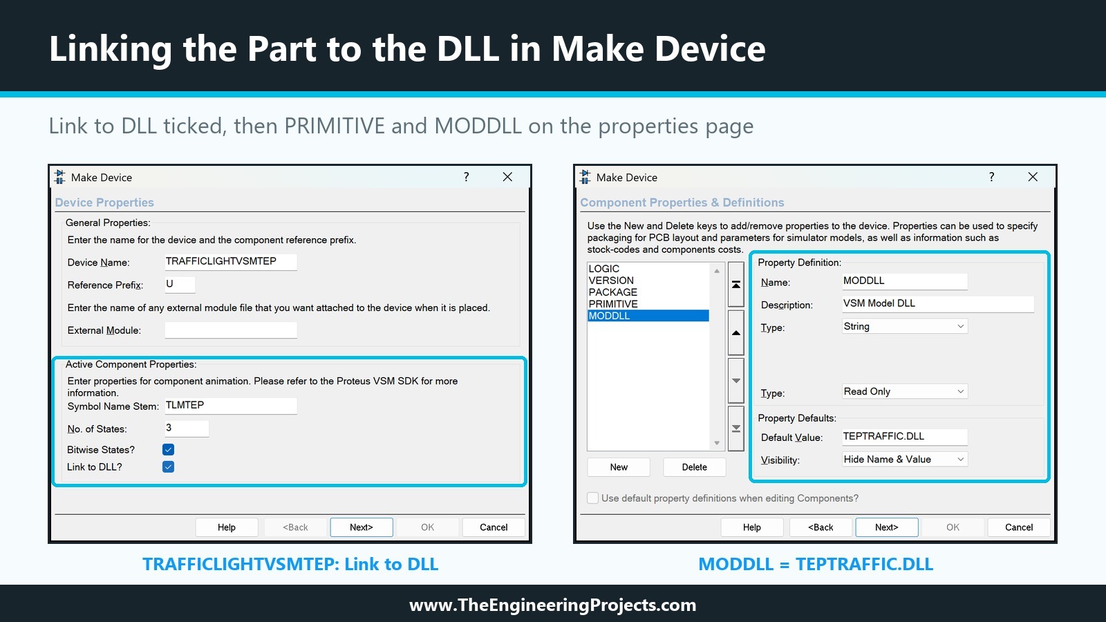
We changed the device name to TRAFFICLIGHTVSMTEP, so the schematic-model version stays available, and kept the prefix U. The Active Component Properties came over from the old part: stem TLMTEP, 3 states, Bitwise States ticked. The new setting is Link to DLL, which we ticked. The help says only that this option specifies whether the component model is linked to a VSM Model DLL; in the stored script, it adds DLL to the end of the ACTIVE line.
Component Properties: PRIMITIVE and MODDLL
On the properties page, we deleted MODFILE, RRED, RYEL and RGRN, which belong to the schematic model, and kept LOGIC, VERSION and PACKAGE. From the New button's list, we added:
- PRIMITIVE, which Proteus defines as Primitive Type, hidden, with the default DIGITAL,TLMTEP. DIGITAL says the model runs in the digital simulator, and TLMTEP is the primitive name passed to the create functions.
- MODDLL, which Proteus defines as VSM Model DLL, read only, with the default TEPTRAFFIC.DLL.
We raised VERSION to 2.0, wrote a new description and notes that name the DLL, and stored the part in TEPTUTORIAL. Here is its script, read from the library file:
; TRAFFICLIGHTVSMTEP version 2.0, read from TEPTUTORIAL.LIB after Make Device
{*DEVICE}
{PREFIX=U}
{ACTIVE=TLMTEP,3,BITWISE,DLL}
{NOTES=Made in the TEP tutorial series How to Create a Proteus Library. Simulation model: TEPTRAFFIC.DLL in the MODELS folder.}
{*PROPDEFS}
{LOGIC="Lamps light when the pin is",HILOW}
{VERSION="Library version",READONLY STRING}
{PACKAGE="PCB Package",PACKAGE,1,TRAFFICLIGHT-TEP}
{PRIMITIVE="Primitive Type",HIDDEN STRING}
{MODDLL="VSM Model DLL",READONLY STRING}
{*INDEX}
{CAT=Optoelectronics}
{SUBCAT=LEDs}
{MFR=The Engineering Projects}
{DESC=Traffic Light LED Module - VSM model TEPTRAFFIC.DLL, LOGIC High or Low (TEP Tutorial)}
{*COMPONENT}
{LOGIC=1}
{VERSION=2.0}
{PACKAGE=TRAFFICLIGHT-TEP}
{PRIMITIVE=DIGITAL,TLMTEP}
{MODDLL=TEPTRAFFIC.DLL}
Step 5: Place the Part and Wire a Test
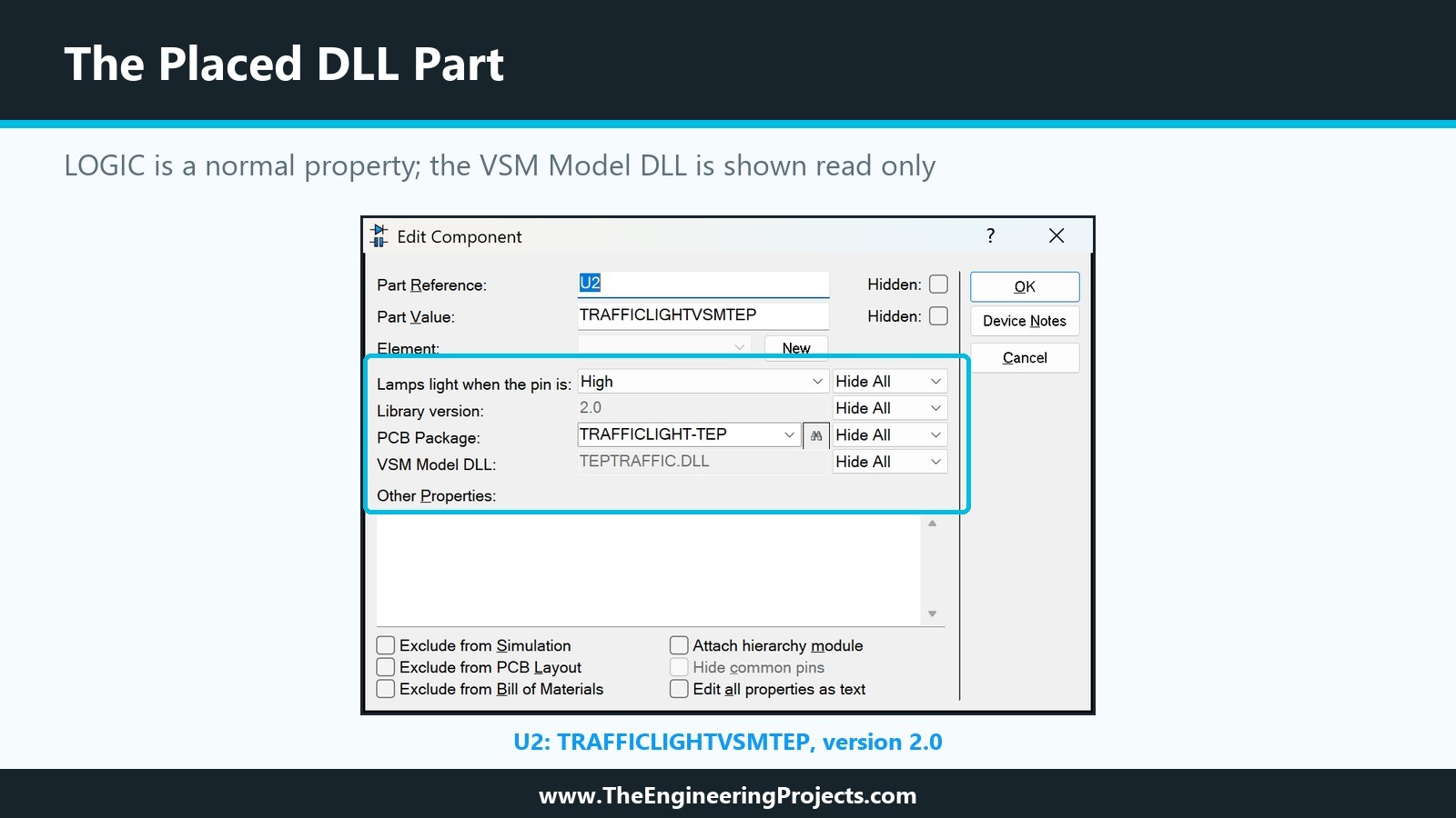
We placed TRAFFICLIGHTVSMTEP as U2 next to our older modules and gave it its own inputs: three LOGICSTATE parts, mirrored so they sit to the right of the pins, on R, Y and G, and a ground terminal on GND. Like any other part, U2 shows its LOGIC property in the Edit Component dialogue, and the MODDLL property appears as VSM Model DLL, greyed out because it is read only.
How to Test the DLL Model
We set the LOGICSTATEs to R = 1, Y = 0 and G = 1, the buggy two-lamp case from our design plan, and ran the simulation four times.
LOGIC High
The first run started without any error, and the message counter on the status bar showed three messages instead of two. The extra one is ours: the Simulation Log listed "TEP Traffic Light: model started, lamps light when a pin is HIGH" with U2 as the source. The red and green lamps lit, the yellow lamp stayed dark, and the pins showed their logic levels with small red and blue squares, which Proteus draws for digital pins during a simulation.
LOGIC Low
We stopped the simulation, changed LOGIC to Low in U2's properties and ran again with the same inputs. Now only the yellow lamp lit, the one whose pin is LOW, and the log said "lamps light when a pin is LOW". This is the behaviour of a module whose LEDs are connected to the supply, without any change to the drawing or the wiring.
A Module Without Ground
Finally, we deleted the wire between GND and the ground terminal. The run showed all three lamps dark although R and G were HIGH, because the model reads an unconnected GND pin as not LOW. We undid the deletion and set LOGIC back to High.
Our model reads LOGIC once, in setup, so a change takes effect at the next run. Changing it while the simulation runs is a job for the next tutorial.
Common Mistakes When Creating a Proteus Model DLL
| Problem | Cause | Solution |
|---|---|---|
| Error C2065: NULL undeclared in vsm.hpp | No standard header included before vsm.hpp | Include <cstddef> first |
| Proteus cannot load the DLL | The DLL is 64-bit | Build with vcvars32.bat and /MACHINE:X86 |
| Model DLL not found | The DLL is not in the module path | Copy it into the MODELS folder |
| The functions are not found | C++ name decoration | Export them with extern "C" and check with dumpbin /exports |
| A LOGIC change has no effect during a run | The model reads properties in setup | Stop and run again, or poll for changes in the model |
| The part draws, but the lamps never change | Link to DLL is not ticked, or PRIMITIVE is missing | Check the ACTIVE line ends in DLL and both PRIMITIVE and MODDLL are set |
In the Next Tutorial
Our model DLL now simulates and draws the module. A DLL can also draw extra graphics and react to the mouse. In the next tutorial, How to Add a Live Control Panel to a Proteus Component, we give our Traffic Light Module a panel next to it that shows its pins and lamps while the simulation runs and lets you change its behaviour with a click.
FAQ
Do I need the VSM SDK to make a Proteus model DLL?
Yes. The interfaces are declared in Labcenter's vsm.hpp, which comes with the VSM SDK. The installed help of Proteus 8.5 asks you to request the SDK from Labcenter, with an NDA and a valid Update Service Contract.
Should a Proteus model DLL be 32-bit or 64-bit?
It must match Proteus. Proteus 8.5 is a 32-bit program, so its model DLLs must be compiled for x86.
Where do I put my model DLL?
In a folder listed under Simulation Model and Module Folders in System Settings, normally the MODELS folder of the installation.
What is the difference between PRIMITIVE and MODDLL?
PRIMITIVE tells Proteus that the part is a primitive and what kind, for example DIGITAL. MODDLL names the DLL that implements it. A VSM model needs both.
Can one DLL model several parts?
Yes. The create functions receive the primitive name, so one DLL can serve several parts, as Labcenter's MCS8051.DLL does for its 8051 variants.
That is all for today. Our Traffic Light Module now has a model written in C++, and its LOGIC property finally does something. If you have any questions, ask in the comments. Take care.