Hello friends, I hope you all are doing great. Today, I am going to share the new PCA9685 Servo Driver and SG90 Servo Motor Library for Proteus V1.0. The blue PCA9685 board is the classic way to drive many servos from one Arduino: two I2C wires give you 16 PWM channels, each with 12-bit resolution, and the Arduino stays free for the rest of your project. Robot arms, hexapods, camera pan-tilts and animatronic eyes all start with this board and a handful of SG90 micro servos. Now you can build and test them in Proteus.
Behind the parts sit our own models. The PCA9685 board has the register set of the datasheet, its internal oscillator and prescaler, SLEEP and RESTART, the six address jumpers and 16 outputs that really switch at the exact counts. The SG90 is a model too: it reads the pulses on its signal wire, and a position loop drives a motor and a gearbox, so the horn turns at the real speed, draws real current from the supply and stalls when you load it too much. You get three devices: the PCA9685 board as a Simple device with a live STATUS panel and as an Advance device with a pop-up window and three test tools, plus the SG90 with its horn. The demo runs on our Arduino UNO V4.0 with the Adafruit PWM Servo Driver library.
NOTICE: a servo library is easy to fake: turn a picture to the angle the sketch asks for. We wanted more. Our SG90 gets the real pulses from the real PCA9685 counts, so a wrong oscillator value, a missing setPWMFreq(50) or a heavy load shows up in Proteus just as on your desk. It took our team a lot of hard work. Your feedback is the fuel that keeps us going, so please tell us what you think in the comments below or in the Motor Driver board of our forum. And if our free libraries help you, you can buy us a coffee. So, let's get started with the PCA9685 Servo Driver and SG90 Servo Motor Library for Proteus V1.0:
What is the PCA9685?
The PCA9685 is an NXP chip with 16 PWM outputs controlled over I2C. It was made for LEDs, but its outputs are just as good for servos, and the breakout board with 16 three-pin servo headers is one of the most popular Arduino modules. All 16 channels share one frequency, from 24 to 1526 Hz, and each channel has its own 12-bit ON and OFF counts, so it can make any pulse in steps of 1/4096 of the period. Once the chip has its registers, it makes the pulses by itself: the Arduino only talks to it when something changes.
| PCA9685 board (the model) | |
|---|---|
| Interface | I2C, up to 1 MHz; SDA, SCL |
| Address | 0x40 + the A0 - A5 jumpers (0x40 - 0x7F), ALL CALL 0x70, three sub-addresses |
| Outputs | 16 PWM channels, 12-bit ON and OFF counts, full ON and full OFF, totem pole or open drain |
| Frequency | 24 - 1526 Hz from the internal 25 MHz oscillator and PRE_SCALE |
| Supplies | VCC 2.3 - 5.5 V for the chip; V+ on the terminal block for the servos |
| Other pins | OE (output enable, pulled LOW on the board), GND |
| Power-up | SLEEP, every output full OFF, PRE_SCALE 30 (197 Hz) |
| Devices in this library | PCA9685TEP (Simple), PCA9685ADVTEP (Advance), SG90TEP (the servo) |
How the PCA9685 Makes a Servo Pulse
The chip counts from 0 to 4095 over and over. The speed of the counter sets the frequency: the internal oscillator runs at 25 MHz, and the PRE_SCALE register divides it. The frequency is 25 MHz / (4096 x (PRE_SCALE + 1)). An analog servo wants 50 Hz, so the library writes PRE_SCALE = 121, which gives 50.03 Hz, a period of 19.99 ms. One count is then 4.88 us long.
Each channel has an ON count and an OFF count. The output goes HIGH when the counter reaches ON and LOW when it reaches OFF. For a 1500 us servo pulse the library writes ON = 0 and OFF = 307: 307 counts of 4.88 us are 1498 us. Two extra bits, full ON and full OFF, hold an output HIGH or LOW for good. One more rule from the datasheet catches many people: PRE_SCALE can only be written while the chip sleeps. A write while it runs is ignored.
What is the SG90 Micro Servo?
The SG90 is the small blue 9 g servo that comes with nearly every Arduino kit. Inside are a small DC motor, a gearbox, a potentiometer on the output shaft and a control board. Every 20 ms the servo gets one pulse on its signal wire, and the width of the pulse is the angle it should hold. The control board compares that with the potentiometer and drives the motor until they match. That is a closed loop inside the servo, but it does not report anything back to the Arduino.
| SG90 (the model) | |
|---|---|
| Supply | 4.8 - 6 V on the red wire (V+) |
| Wires | brown GND, red V+, orange SIG |
| Pulses | 500 - 2500 us = 0 - 180 deg (properties PULSE_MIN, PULSE_MAX), one every 20 ms |
| Speed | 60 deg in 0.149 s at 4.8 V, 0.125 s at 6 V |
| Torque | 1.8 kg.cm at 4.8 V |
| Current | about 6 mA at rest, about 0.65 A when it starts or stalls |
| End stops | at -8 and 188 deg |
| On the schematic | the horn turns at the real angle; ANGLE, PULSE, CURRENT and the LOAD button |
What's New in PCA9685 Servo Driver and SG90 Servo Motor Library for Proteus V1.0
- The real PCA9685 board: the blue PCB with the chip, the 6-pin headers on both ends, the green V+ terminal block, the PWR LED, the capacitor, the A0 - A5 address jumpers, which you can click while the simulation runs, and the 16 servo headers.
- The register set of the datasheet: MODE1 and MODE2, the 16 channels, ALL_LED, PRE_SCALE, the sub-addresses, ALL CALL, the software reset, auto-increment, SLEEP, RESTART and the power-up values.
- Real PWM pins: every output switches HIGH and LOW at its exact counts, so any part or instrument on the pin sees the real signal.
- An SG90 with a moving horn that turns at the simulated speed, draws its current from V+, pushes against its end stops and stalls under the LOAD brake.
- Mistake detection: no setPWMFreq(50), a wrong oscillator value, a pulse beyond the servo's range, the wrong I2C address, open-drain outputs, PRE_SCALE written while awake, no power on V+.
- Three test tools on the Advance device: Registers, I2C bus and Servo check.
- A two-node demo on our Arduino UNO V4.0 with four SG90 servos and serial commands for every mistake.
- A compact package: about 1.29 MB, without the C++ source code of the model.
Three Devices: Simple, Advance and the SG90
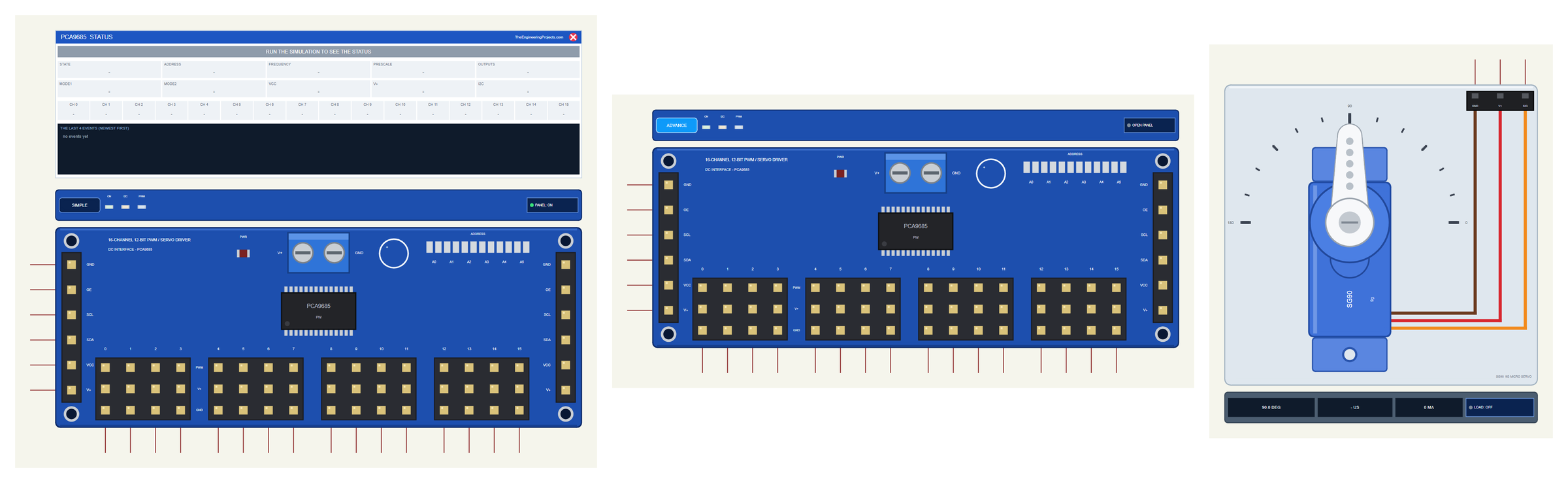
| Simple | Advance | Servo | |
|---|---|---|---|
| Device | PCA9685TEP | PCA9685ADVTEP | SG90TEP |
| On the schematic | The board + the STATUS panel | The board only | The SG90 with its horn |
| Status | Banner, 10 readouts, 16 channels, the last 4 events | A pop-up: Board, Event log, Tests | ANGLE, PULSE, CURRENT |
| Interaction | PANEL button, the A0 - A5 jumpers | OPEN PANEL button, the A0 - A5 jumpers | LOAD button |
Download PCA9685 Servo Driver and SG90 Servo Motor Library for Proteus
Click the button below to download PCA9685-Servo-Driver-Library-for-Proteus-v1.0.zip (about 1.29 MB, without the C++ source code of the model):
PCA9685 Servo Driver and SG90 Servo Motor Library for Proteus V1.0- README.txt: the devices, installation, the demo, wiring, the test tools and real hardware.
- Proteus Library Files:
TEPPCA9685.LIBandArduinoV4TEP.LIBfrom our Arduino Library for Proteus V4.0. - Proteus Model Files:
TEPPCA9685.DLLandTEPARDUINO.DLL. - Proteus Simulation:
PCA9685-Servo-Driver-ArduinoUnoV4.pdsprj,PCA9685_Demo.hexand copies of the two DLLs. - Arduino Code:
PCA9685_Demo.ino. The Adafruit libraries it uses come from the Library Manager of the Arduino IDE.
No Proteus yet? Read How to Download and Install Proteus 7 and 8. New to libraries? Follow How to Install a New Library in Proteus.
How to Install PCA9685 Servo Driver and SG90 Servo Motor Library for Proteus
- Close Proteus and extract the whole zip file, for example to your Desktop.
- Copy the two files from Proteus Library Files into the LIBRARY folder of Proteus (usually
C:\Program Files (x86)\Labcenter Electronics\Proteus 8 Professional\LIBRARY). - Copy
TEPPCA9685.DLLandTEPARDUINO.DLLfrom Proteus Model Files into the MODELS folder. - Delete
TEPPCA9685.IDXfrom the LIBRARY folder if it is there. - Start Proteus, press P and search for PCA9685 or SG90.
Tip: keep the Proteus Simulation folder together, because the project needs its .hex file and the DLLs beside it. The library is tested in Proteus 8.5; Proteus 7 is not supported. For DC motors, see our L9110S and TB6612FNG libraries; for stepper motors, our A4988 / DRV8825 library.
The PCA9685 Board in Proteus
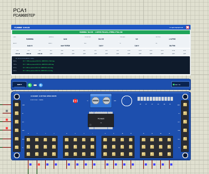
The board looks like the one on your desk: the PCA9685 chip in the middle, the 6-pin headers GND, OE, SCL, SDA, VCC and V+ on both ends, the green terminal block for the servo supply, the PWR LED, the big capacitor and the six address jumpers A0 to A5. The 16 servo headers sit in four groups of four, and the PWM pins come out along the bottom edge. Under the board is the TEP strip with the ON LED for the supply, the I2C LED that flashes with every transaction and the PWM LED that lights while the outputs run. The strip, its LEDs and the panels are TEP additions; the real board has none of them.
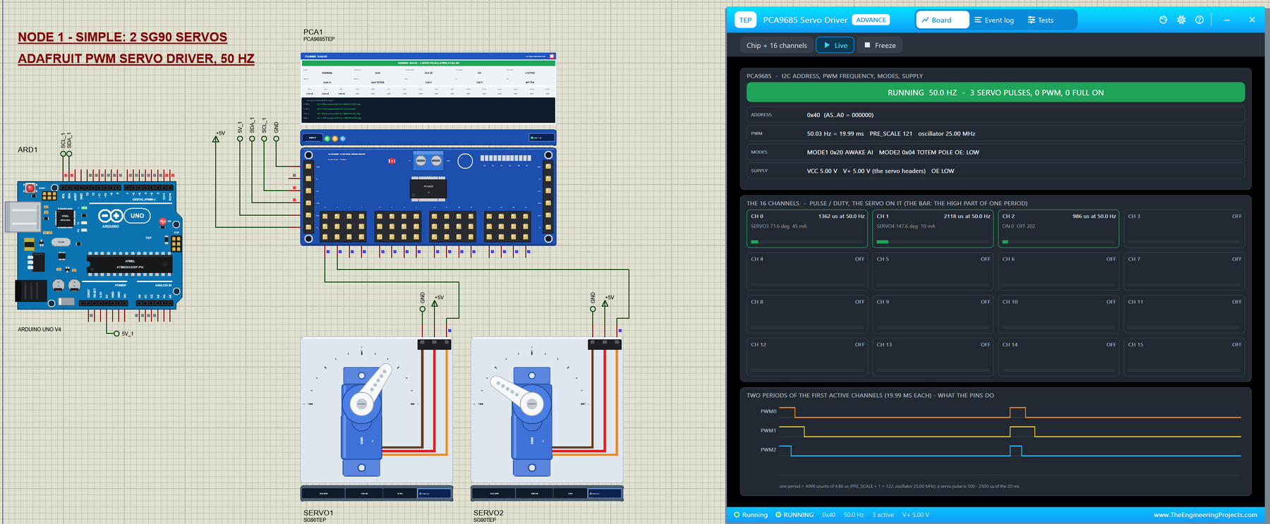
The Simple device adds the STATUS panel. Its banner says what the chip does, for example "RUNNING 50.0 HZ - 3 SERVO PULSES, 0 PWM, 0 FULL ON". Ten readouts follow: the state, the address, the frequency, PRE_SCALE, the outputs, MODE1, MODE2, VCC, V+ and the I2C transactions. Under them are the 16 channels with their pulse or duty, and at the bottom the last four events. The red X closes the panel, and the PANEL button on the strip opens it again.

The banner is the first place to look. Green means the chip runs, red shows the latest warning, for example a stalled servo, grey means SLEEP and amber means the channels are stopped and wait for RESTART.
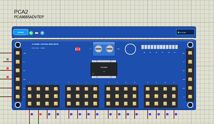
The Advance device keeps the schematic clean: only the board and its strip. Its live data opens in a pop-up window at Run, and the OPEN PANEL button brings the window back if you close it. On both devices you can click an address jumper during the simulation, and the board answers at its new address at once. We will use that later for a classic mistake.
The SG90 Servo in Proteus
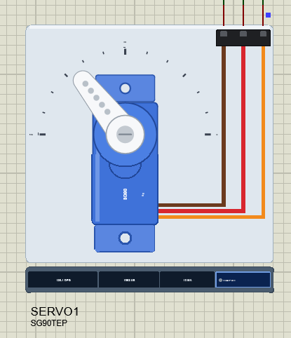
The SG90 is drawn from the top: the blue body with its mounting ears, the white horn on the output shaft and a scale from 0 to 180 degrees around it. The brown, red and orange wires run to a plug with the pins GND, V+ and SIG. While the simulation runs, the horn turns at the angle of the model. The strip under the servo shows the ANGLE, the PULSE it gets and the CURRENT it draws, and holds the LOAD button.
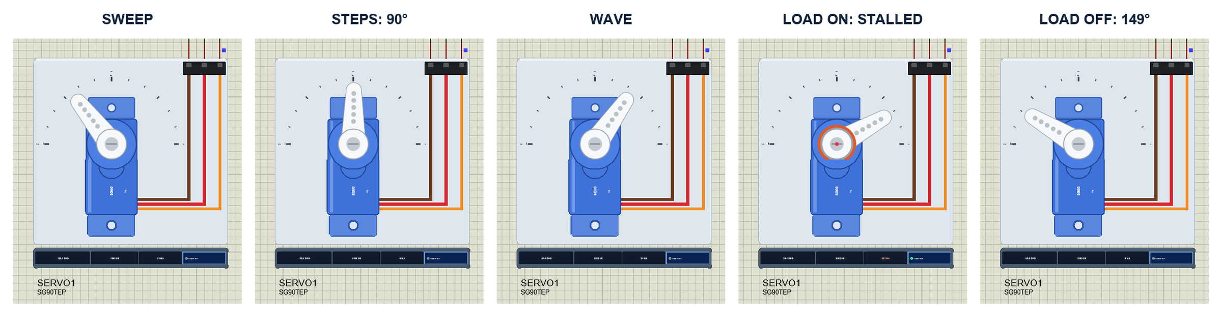
The horn does not jump to the angle. The model decodes each pulse, and a position loop drives the motor with the voltage on V+. The motor has its resistance and back-EMF, the gearbox its friction, the horn its inertia. So the servo needs time: on a PC we measured 60 degrees in 0.149 s at 4.8 V and 0.125 s at 6 V, with a top speed of about 590 degrees per second and no overshoot. At rest it draws about 6 mA; while it moves, several hundred. And like a real analog servo, it only drives its motor while pulses come in: without pulses the horn is not driven and holds by the friction of the gears.
The LOAD Button and a Stalled Servo
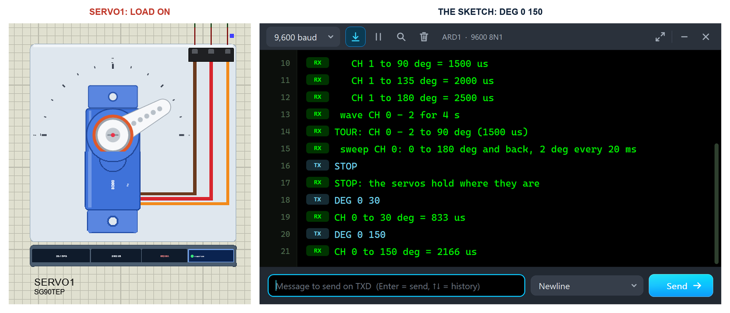
Click LOAD under a servo and a brake of 2.5 kg.cm presses on the horn. The SG90 gives only 1.8 kg.cm at 4.8 V, so it cannot turn: the motor pushes with everything it has and the current jumps to its stall value. In the run, LOAD was pressed while SERVO1 held 30 degrees, then the sketch asked for 150 degrees:
STOP
STOP: the servos hold where they are
DEG 0 30
CH 0 to 30 deg = 833 us
DEG 0 150
CH 0 to 150 deg = 2166 us
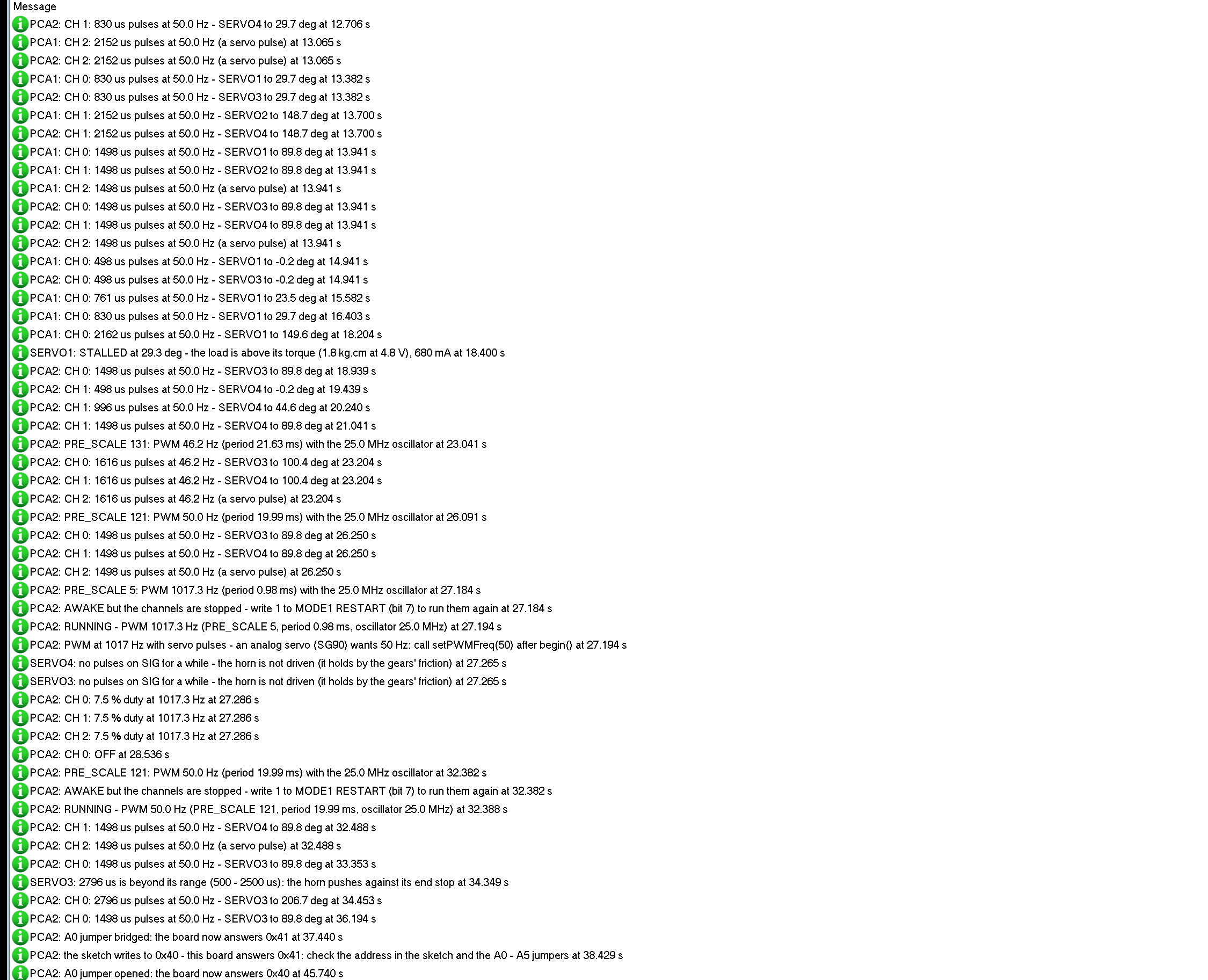
The servo stayed at 29.3 degrees and the log said "SERVO1: STALLED at 29.3 deg - the load is above its torque (1.8 kg.cm at 4.8 V), 680 mA". When LOAD was released, the horn went on to 149.2 degrees. The sketch never knew: a hobby servo has no wire that tells the Arduino where it is. And a stalled servo is the classic reason why an Arduino resets when the servos start: four SG90 servos can draw more than 2 A for a moment. The property LOAD adds a constant load in kg.cm for the whole run.
The Demo Circuit
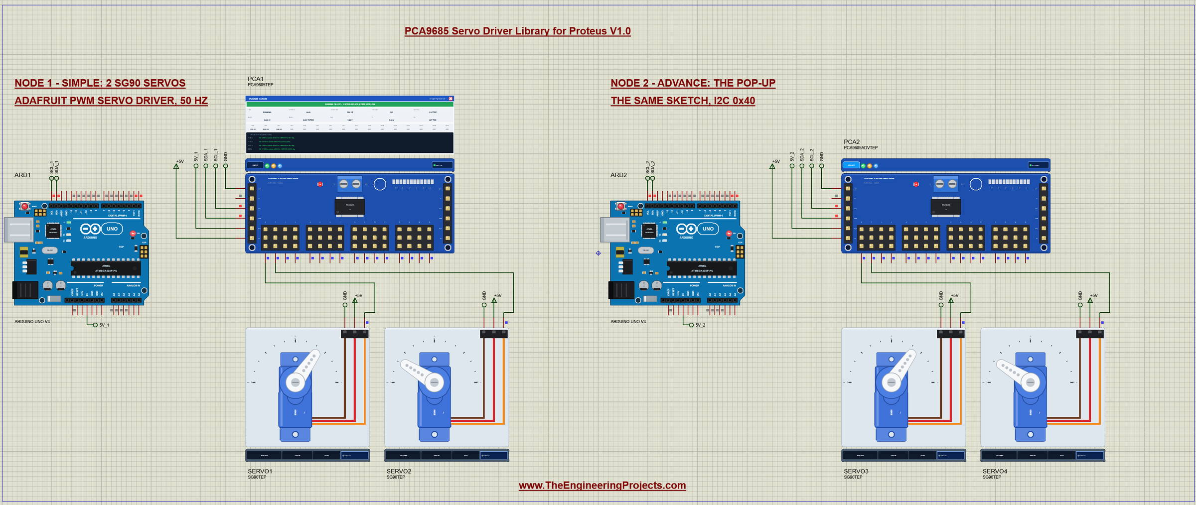
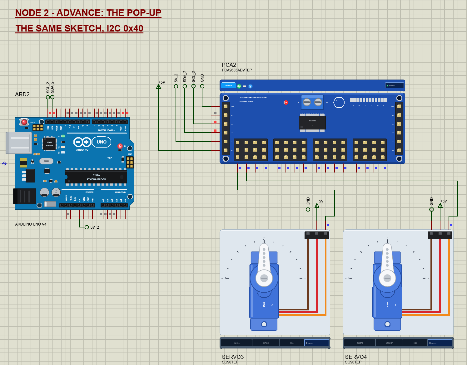
The demo project has two nodes. Each one is an Arduino UNO V4.0 from our Arduino UNO Library for Proteus V4.0, one PCA9685 board and two SG90 servos on channels 0 and 1. Both UNOs run the same PCA9685_Demo.hex with the board at address 0x40 and 50 Hz. Node 1 uses the Simple board, node 2 the Advance board with its pop-up. Channel 2 has no servo, so you can watch a third set of pulses on the board. The V+ of both boards and the servos' red wires come from a +5V power terminal, which Proteus turns into a 5 V supply.
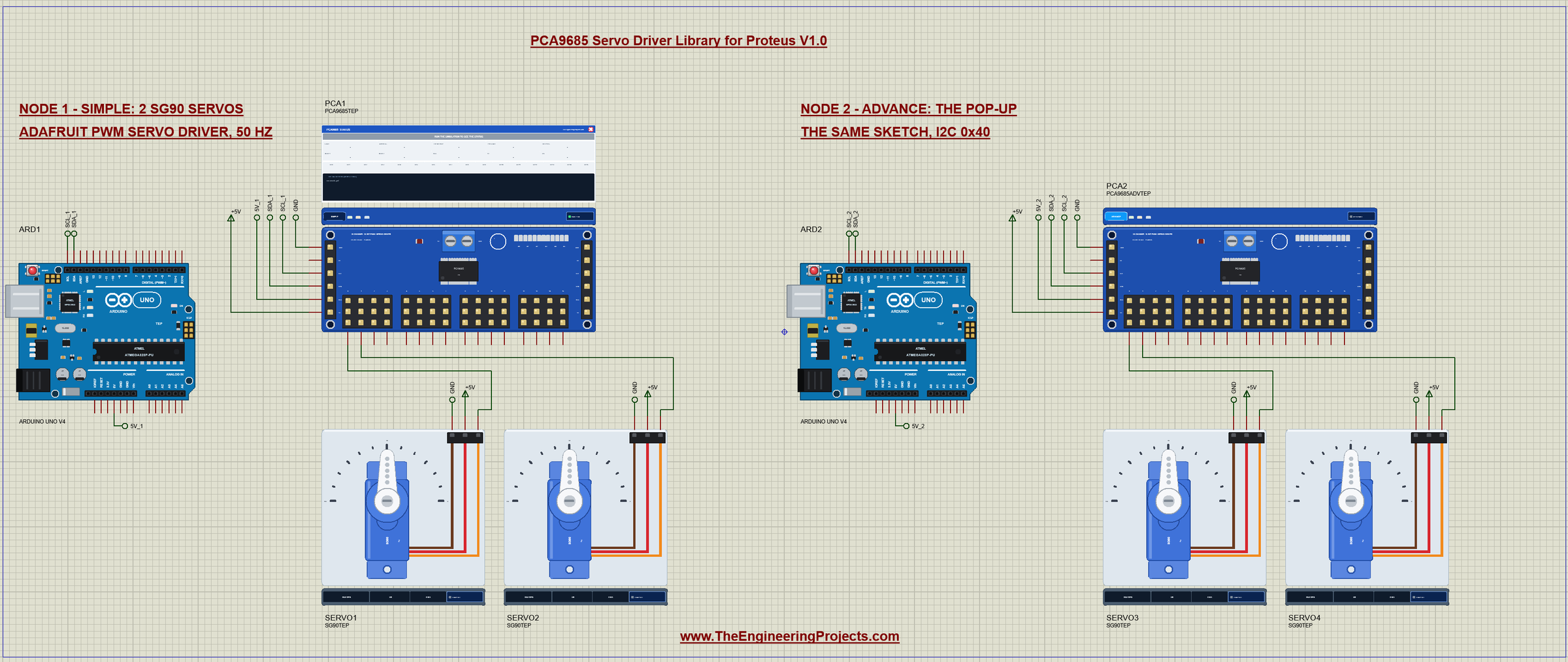
Wiring
| PCA9685 board | Arduino UNO | Note |
|---|---|---|
| GND | GND | common ground |
| OE | open | the board pulls it LOW: the outputs on |
| SCL | SCL (A5) | the I2C clock |
| SDA | SDA (A4) | the I2C data |
| VCC | 5V | the chip's supply |
| V+ | a 5 - 6 V supply | the servos' supply on the terminal block (not the Arduino's 5V pin) |
| PWM 0 - 15 | SG90 orange (SIG) | brown to GND, red to V+ (the header rows) |
In Proteus every board pin reaches its UNO through a wire with a net label: SCL_1, SDA_1 and 5V_1 for node 1, and the same with _2 for node 2. The UNO's SDA and SCL pins next to AREF are the same pins as A4 and A5. The servos' signal wires run straight to the PWM pins, their GND to the ground and their V+ to the +5V terminal. The serial monitor needs no wires at all, because it is built into the UNO V4.0.
Node 1: the Simple Board
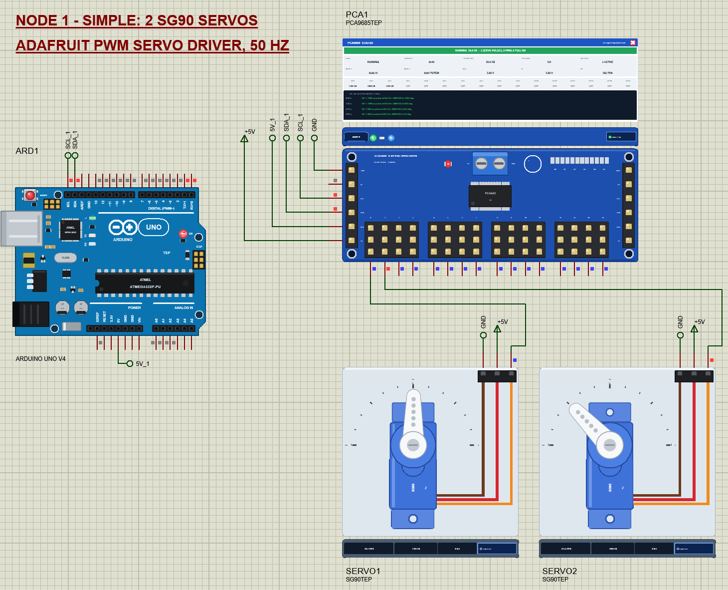
Node 1 shows the whole story on the schematic: the STATUS panel over the board, the horns and the readouts under the servos. The tour turns all three channels to 90 degrees, sweeps CH 0 slowly from 0 to 180 degrees and back, steps CH 1 through 0, 45, 90, 135 and 180 degrees, and ends with a wave on CH 0 to 2, a third of a period apart. Then it starts again.
Node 2: the Advance Board
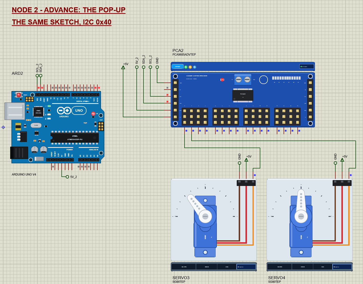
Node 2 runs the same sketch on the Advance board. Its data is in the pop-up, and its monitor is the one we use for the mistakes later in this article.
The Arduino Code
The demo uses the Adafruit PWM Servo Driver library (BSD licence), with Adafruit BusIO and Arduino's Wire library. Install it from the Library Manager of the Arduino IDE. New to Arduino? Start with Arduino Tutorial for Beginners and Introduction to Arduino UNO. The sketch begins with the address, the pulse range of the SG90 and the oscillator it assumes:
#include <Wire.h>
#include <Adafruit_PWMServoDriver.h>

const uint8_t ADDRESS = 0x40;                // the board with A0 - A5 open
const uint16_t US_MIN = 500, US_MAX = 2500;   // the SG90: 0 deg and 180 deg
const uint8_t TOUR_SERVOS = 3;               // CH 0 - 2 move in the tour

Adafruit_PWMServoDriver pwm(ADDRESS);
uint32_t oscillator = 25000000;              // what the sketch assumes (the PCA9685's 25 MHz; real chips: 23 - 27 MHz)
float freq = 50;                             // analog servos want 50 Hz
In setup() the sketch starts the library, tells it the oscillator frequency and sets 50 Hz:
if (pwm.begin()) { Serial.print(F("PCA9685 at 0x")); Serial.print(ADDRESS, HEX); Serial.println(F(": found")); } pwm.setOscillatorFrequency(oscillator);
pwm.setPWMFreq(freq);
printFreq();begin() resets the chip and sets 1000 Hz, its own default; setPWMFreq(50) puts the chip to sleep, writes PRE_SCALE, wakes it and restarts the channels. printFreq() reads PRE_SCALE back and prints the frequency the sketch believes:
void printFreq() {
  const uint8_t pre = pwm.readPrescale();
  Serial.print(F("setPWMFreq(")); Serial.print(freq, 0); Serial.print(F("): PRE_SCALE ")); Serial.print(pre);
  Serial.print(F(" = ")); Serial.print(oscillator / 4096.0 / (pre + 1), 1); Serial.print(F(" Hz (oscillator "));
  Serial.print(oscillator / 1e6, 1); Serial.println(F(" MHz)"));
}
An angle becomes a pulse width, and writeMicroseconds() turns the pulse width into the 12-bit OFF count:
uint16_t usFor(int deg) { return US_MIN + (long)(US_MAX - US_MIN) * deg / 180; }

void servoTo(uint8_t ch, int deg) {          // writeMicroseconds() reads PRE_SCALE and computes the 12-bit count
  deg = constrain(deg, 0, 180);
  angle[ch] = deg;
  pwm.writeMicroseconds(ch, usFor(deg));
}
Note the comment: writeMicroseconds() reads PRE_SCALE from the chip before every channel write, so each servo move costs two extra I2C transactions. You can see them in the I2C bus tool later. The sweep moves CH 0 by 2 degrees every 20 ms, one step per servo period:
  } else if (stage == 1) {                   // sweep: 0 .. 180 .. 0 in 2 deg steps
    if (step == 0) { servoTo(0, 0); nextAt = now + 400; ++step; return; }
    const int k = step - 1;                  // 0 .. 179
    servoTo(0, k < 90 ? 2 * k : 360 - 2 * k);
    if (++step > 181) { servoTo(0, 90); startStage(2); nextAt = now + 500; return; }
    nextAt = now + 20;
The wave gives each servo a sine, a third of a period apart:
    const float t = (now - stageAt) / 1000.0;
    for (uint8_t ch = 0; ch < TOUR_SERVOS; ++ch) servoTo(ch, 90 + 60 * sin(2 * PI * (t / 2.0 + ch / 3.0)));
The commands call the library directly. FREQ and OSC are there to make the two most common mistakes on purpose:
  } else if (!strcmp(s, "FREQ") && v1 > 0) {
    freq = v1; pwm.setPWMFreq(freq); printFreq();
  } else if (!strcmp(s, "OSC") && v1 > 0) {
    oscillator = v1; pwm.setOscillatorFrequency(oscillator); pwm.setPWMFreq(freq);
} else if (!strcmp(s, "SLEEP")) { pwm.sleep(); Serial.println(F("SLEEP: the oscillator stops - no more pulses")); }
else if (!strcmp(s, "WAKE")) { pwm.wakeup(); Serial.println(F("WAKE: the oscillator runs again")); }SCAN asks every I2C address and prints the ones that answer:
for (uint8_t a = 1; a < 127; ++a) { Wire.beginTransmission(a); if (Wire.endTransmission() == 0) { Serial.print(F(" 0x")); Serial.print(a, HEX); ++n; } }The HEX file is in the package. To change the sketch, install the Adafruit PWM Servo Driver library, open the sketch in the Arduino IDE and export the compiled binary, as in How to get the HEX file from Arduino. It needs 14,004 bytes of flash and 614 bytes of RAM.
The Serial Monitor
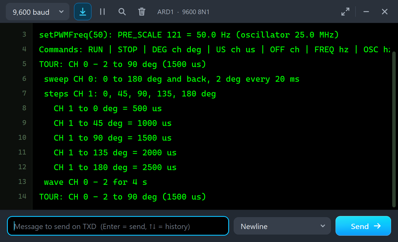
Both UNOs have the serial monitor built in, and it opens at Run. The screenshots use its Simple interface. After its title and "PCA9685 at 0x40: found", node 1 prints:
setPWMFreq(50): PRE_SCALE 121 = 50.0 Hz (oscillator 25.0 MHz)
Commands: RUN | STOP | DEG ch deg | US ch us | OFF ch | FREQ hz | OSC hz | SLEEP | WAKE | SCAN | WHERE | HELP
TOUR: CH 0 - 2 to 90 deg (1500 us)
 sweep CH 0: 0 to 180 deg and back, 2 deg every 20 ms
 steps CH 1: 0, 45, 90, 135, 180 deg
   CH 1 to 0 deg = 500 us
   CH 1 to 45 deg = 1000 us
   CH 1 to 90 deg = 1500 us
   CH 1 to 135 deg = 2000 us
   CH 1 to 180 deg = 2500 us
 wave CH 0 - 2 for 4 s
Commands
Type a command in the monitor and press Enter. STOP stops the tour and the servos hold, DEG 0 30 turns a channel to an angle, US 0 2800 sends a raw pulse, OFF 0 switches a channel full OFF, FREQ calls setPWMFreq(), OSC changes the oscillator the sketch assumes, SLEEP and WAKE put the chip to sleep and wake it, SCAN searches the I2C bus, WHERE prints the angle each channel was told, RUN starts the tour again and HELP lists them all.
The Advance Pop-Up Window
At Run, the Advance device opens TEP PCA9685 Servo Driver Advance, with the look of our TEP Serial Monitor Advance for Proteus. It has three tabs, Board, Event log and Tests, plus Settings and Help behind the gear and question mark icons.
The Board Page
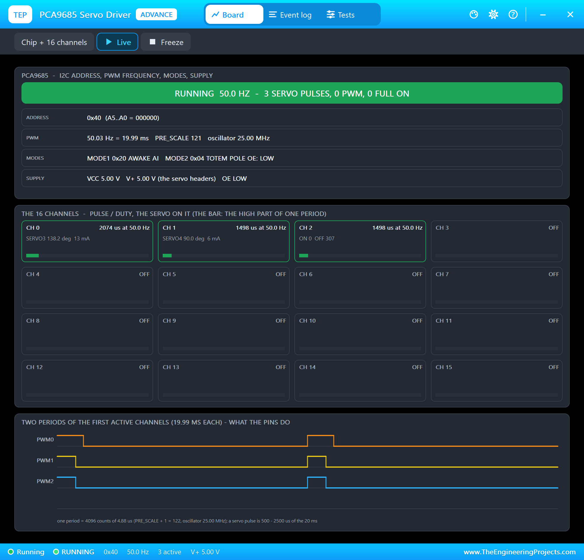
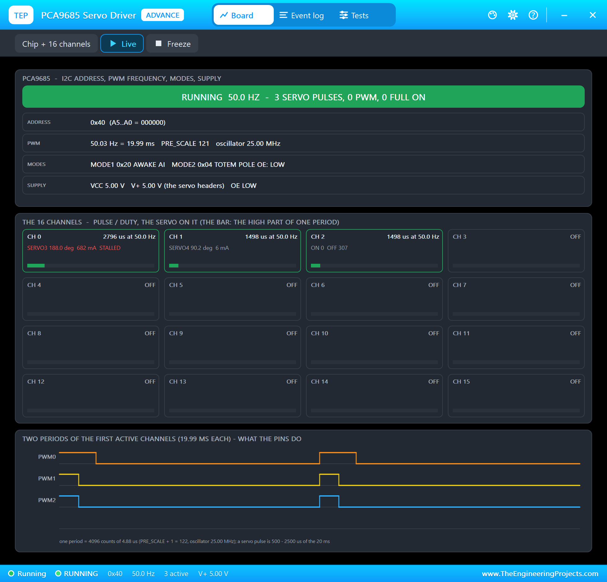
The top card is the chip: the state in big letters, the address with its jumpers, the frequency with PRE_SCALE and the oscillator, MODE1 and MODE2 in words, VCC, V+ and OE. Under it are the 16 channels. Each cell shows the pulse or the duty, the servo on that channel with its angle and current, and a bar with the HIGH part of one period. The model finds each SG90 through the wire on its SIG pin, so the board knows which servo sits on which channel.
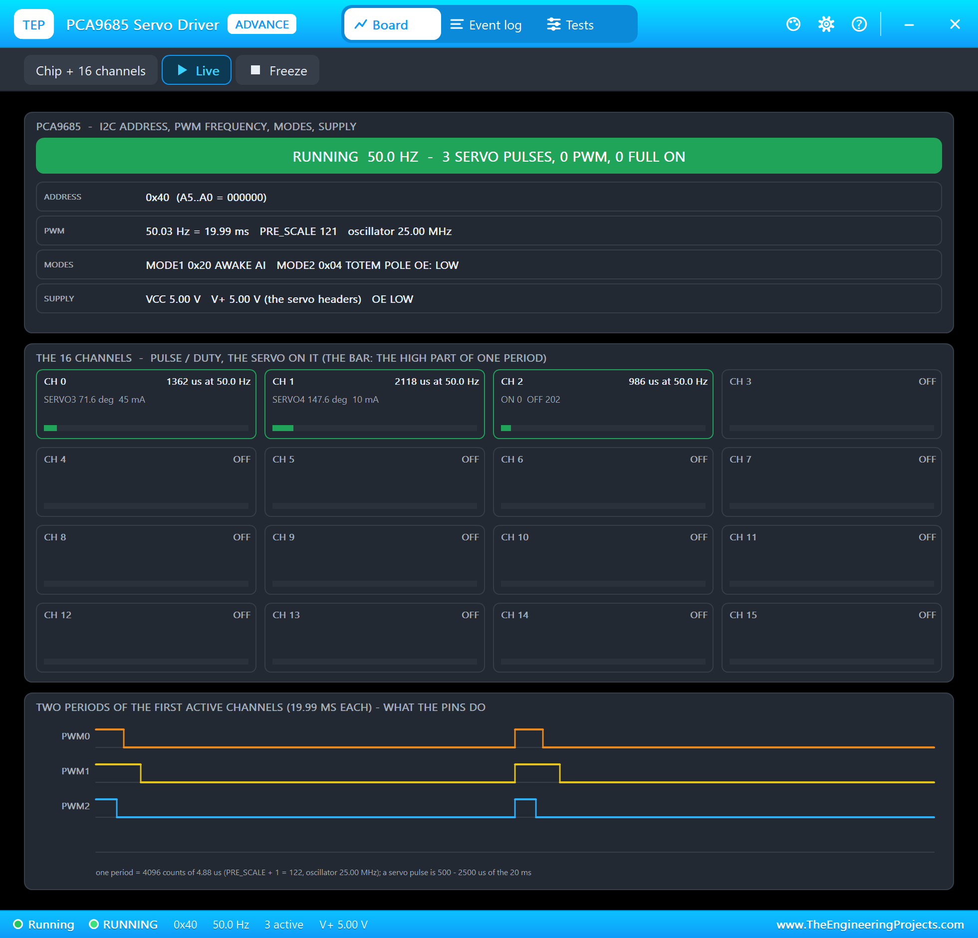
At the bottom are two periods of the first active channels: what the pins really do. All 16 channels start their period together, so every pulse begins at count 0 and only the falling edge moves. Freeze holds the page for a closer look.
Event Log
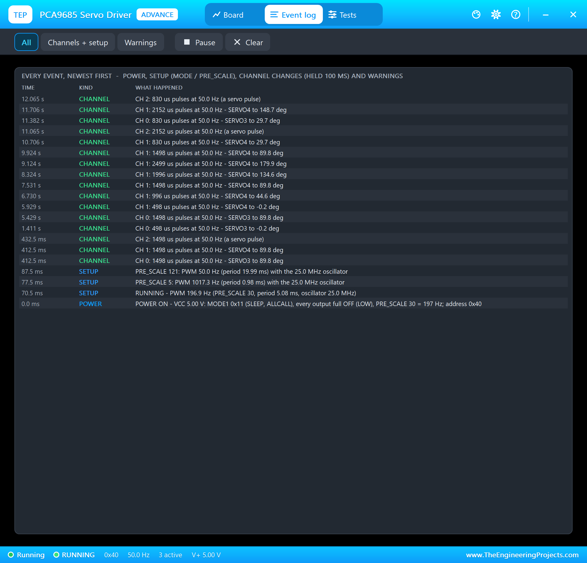
The Event log lists power on and off, every frequency change, every channel that held a new value for 100 ms, SLEEP and RESTART, the address jumpers, the warnings and the notes of the servos. Read the start from the bottom: "POWER ON - VCC 5.00 V: MODE1 0x11 (SLEEP, ALLCALL), every output full OFF (LOW), PRE_SCALE 30 = 197 Hz", then "PRE_SCALE 5: PWM 1017.3 Hz" from begin(), and "PRE_SCALE 121: PWM 50.0 Hz (period 19.99 ms)". Filter the log by channels or warnings, pause it, or clear it.
The Test Tools
The Tests tab holds three tools. Each one reads the board as the model sees it, and where it judges, gives every row a green, amber or red verdict.
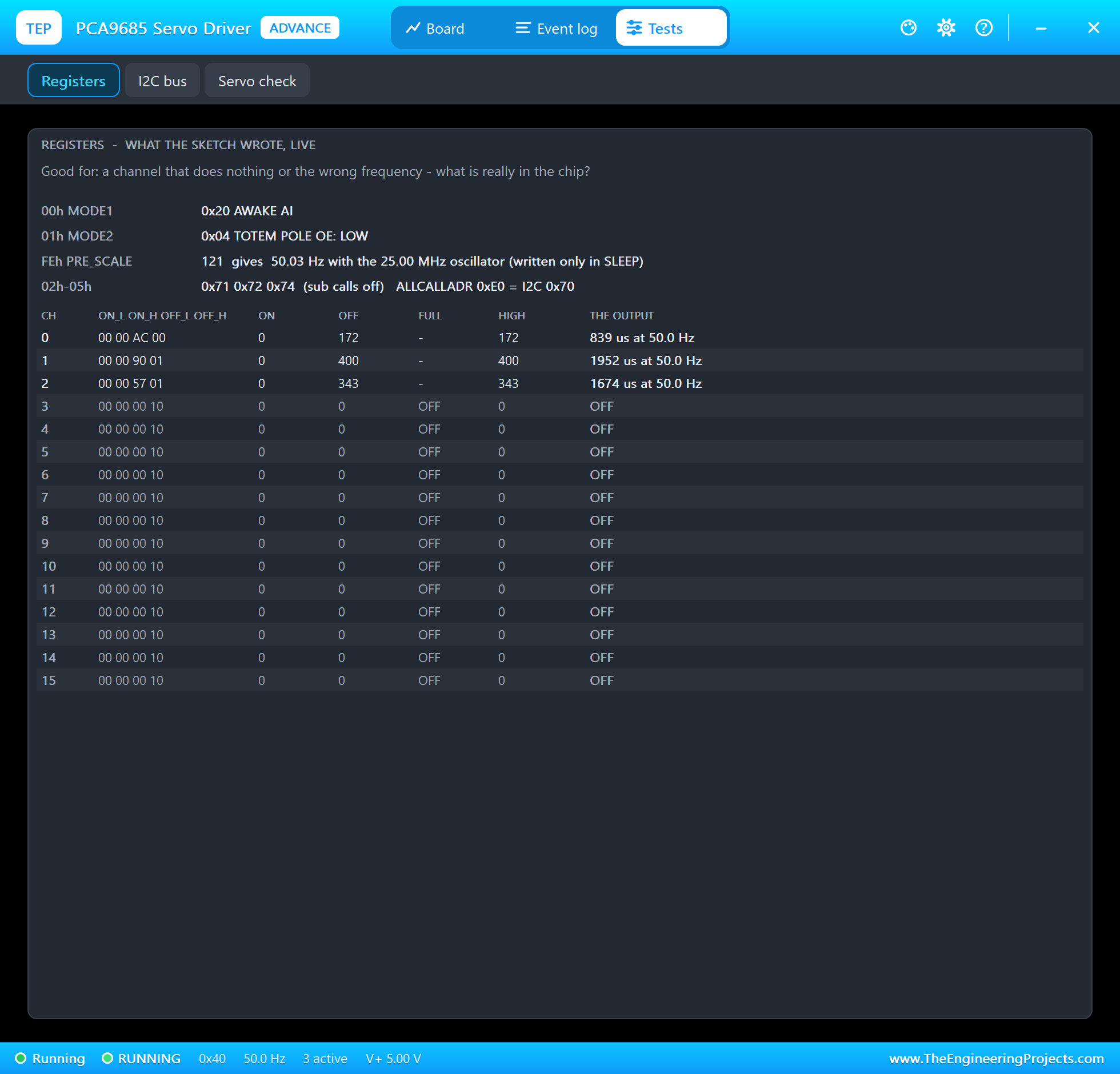
Registers is good for a channel that does nothing or the wrong frequency. It shows MODE1 and MODE2 in words, PRE_SCALE with the frequency it gives, the sub-addresses and ALL CALL, and the 16 channels with their four raw bytes, the ON and OFF counts, the full ON and full OFF bits and the pulse. The unused channels show 00 00 00 10: the full-OFF bit from the power-up. Note MODE1: 0x20 has no ALLCALL bit, because the library's begin() writes MODE1 with only RESTART set, which clears it.
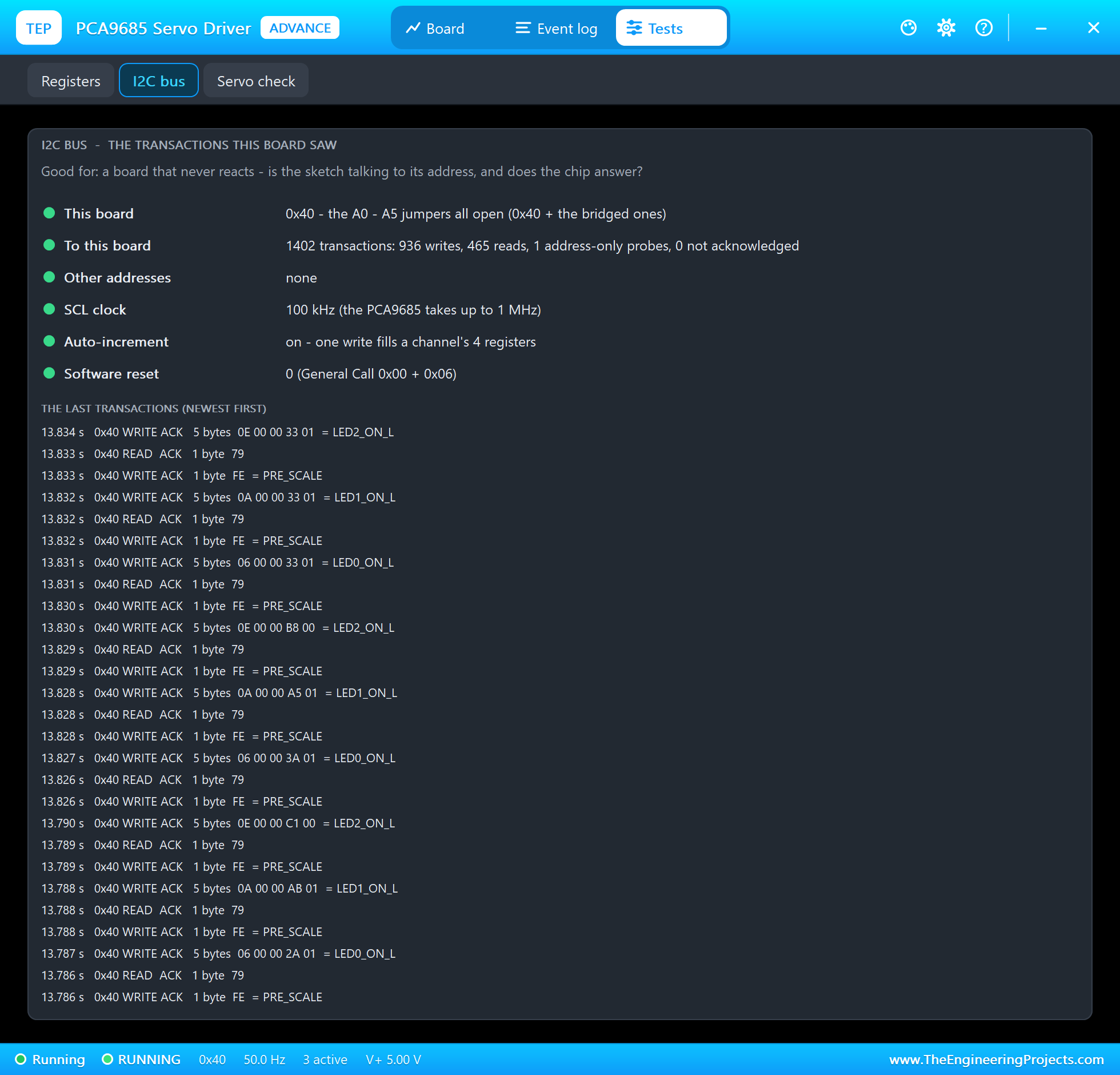
I2C bus is good for a board that never reacts. It shows the address with its jumpers, the transactions to this board, the writes to other addresses, the SCL clock (100 kHz from the Wire library), auto-increment and the software resets. Under them are the last transactions with their bytes and register names. Here you see the pattern of writeMicroseconds(): a write of the PRE_SCALE pointer, a read of one byte (0x79 = 121), then five bytes to LEDn_ON_L, the channel's four registers in one go thanks to auto-increment.
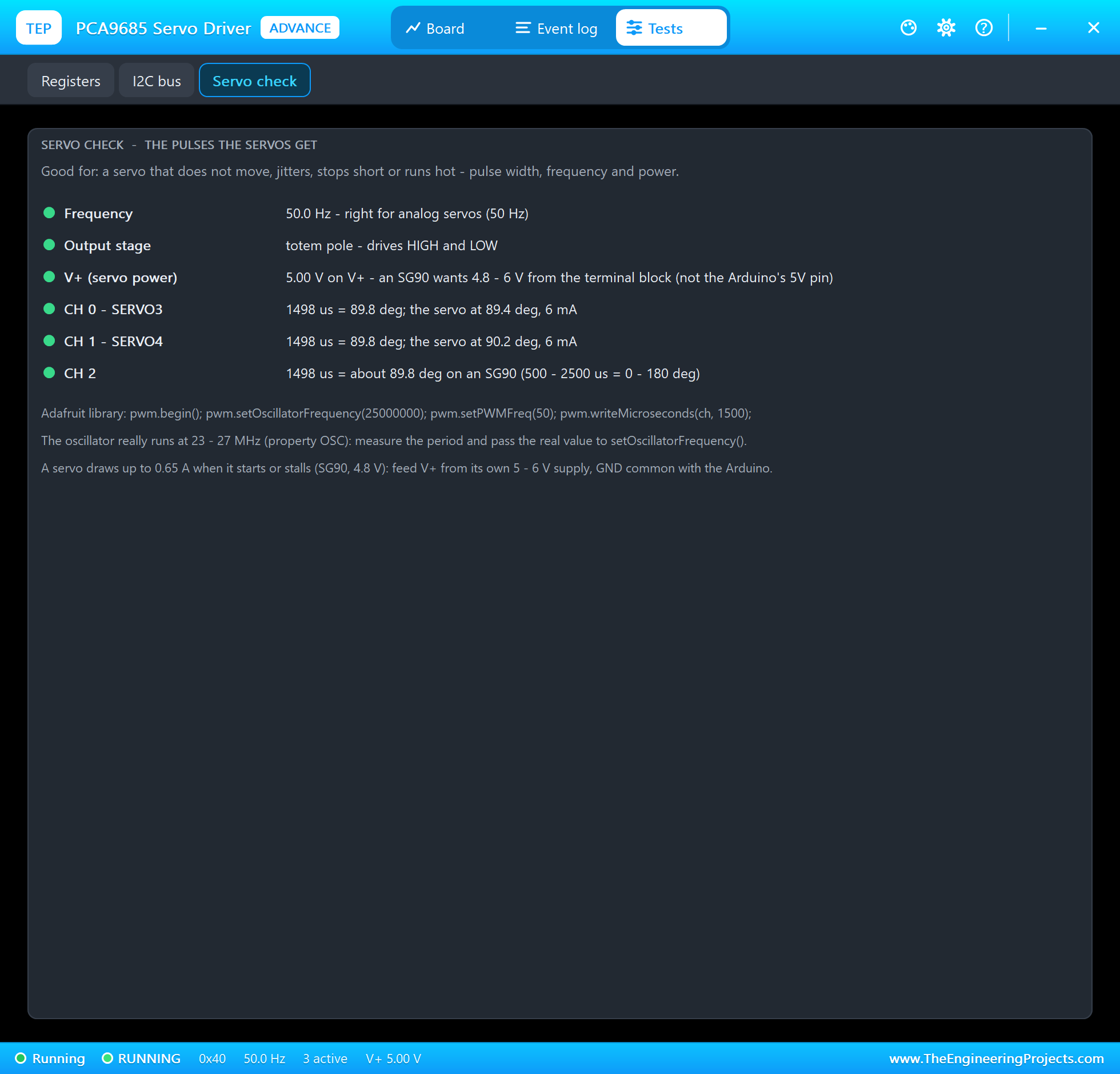
Servo check is good for a servo that does not move, jitters, stops short or runs hot. It checks the frequency against 50 Hz, the output stage (totem pole or open drain), the voltage on V+, and every channel with a servo: the pulse, the angle it means, and the angle and current of the servo itself. Under them are three tips for real hardware.
Classic PCA9685 Mistakes, Simulated
The demo sketch can make the most common PCA9685 mistakes on purpose, so you can see what they look like before they happen on your desk. All of them were run on node 2 in the final test.
The Oscillator Is Not Exactly 25 MHz
The datasheet says the internal oscillator runs at 25 MHz, but real chips run anywhere from 23 to 27 MHz. That is why the Adafruit library has setOscillatorFrequency(). What happens if the value does not match the chip? Type OSC 27000000:
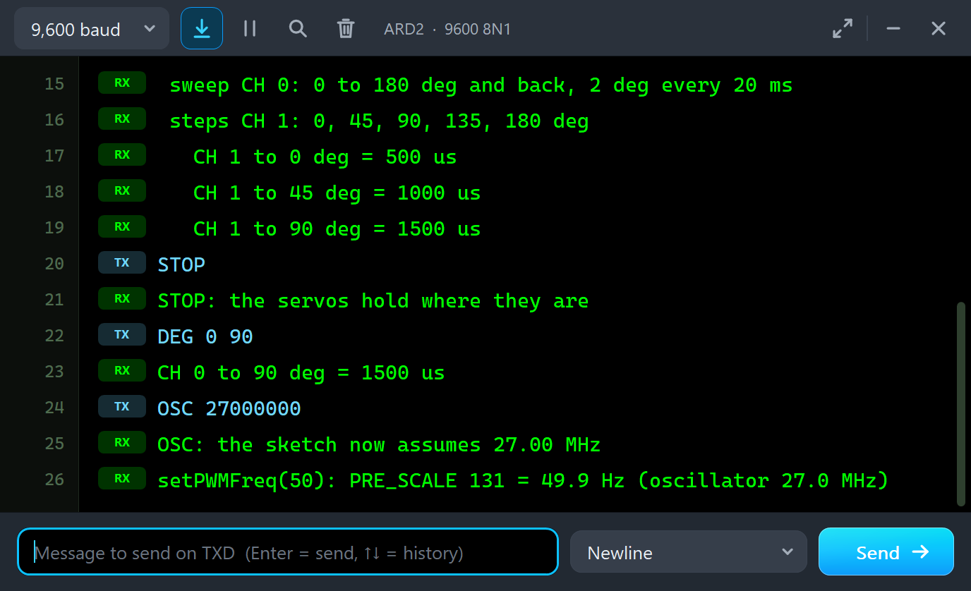
DEG 0 90
CH 0 to 90 deg = 1500 us
OSC 27000000
OSC: the sketch now assumes 27.00 MHz
setPWMFreq(50): PRE_SCALE 131 = 49.9 Hz (oscillator 27.0 MHz)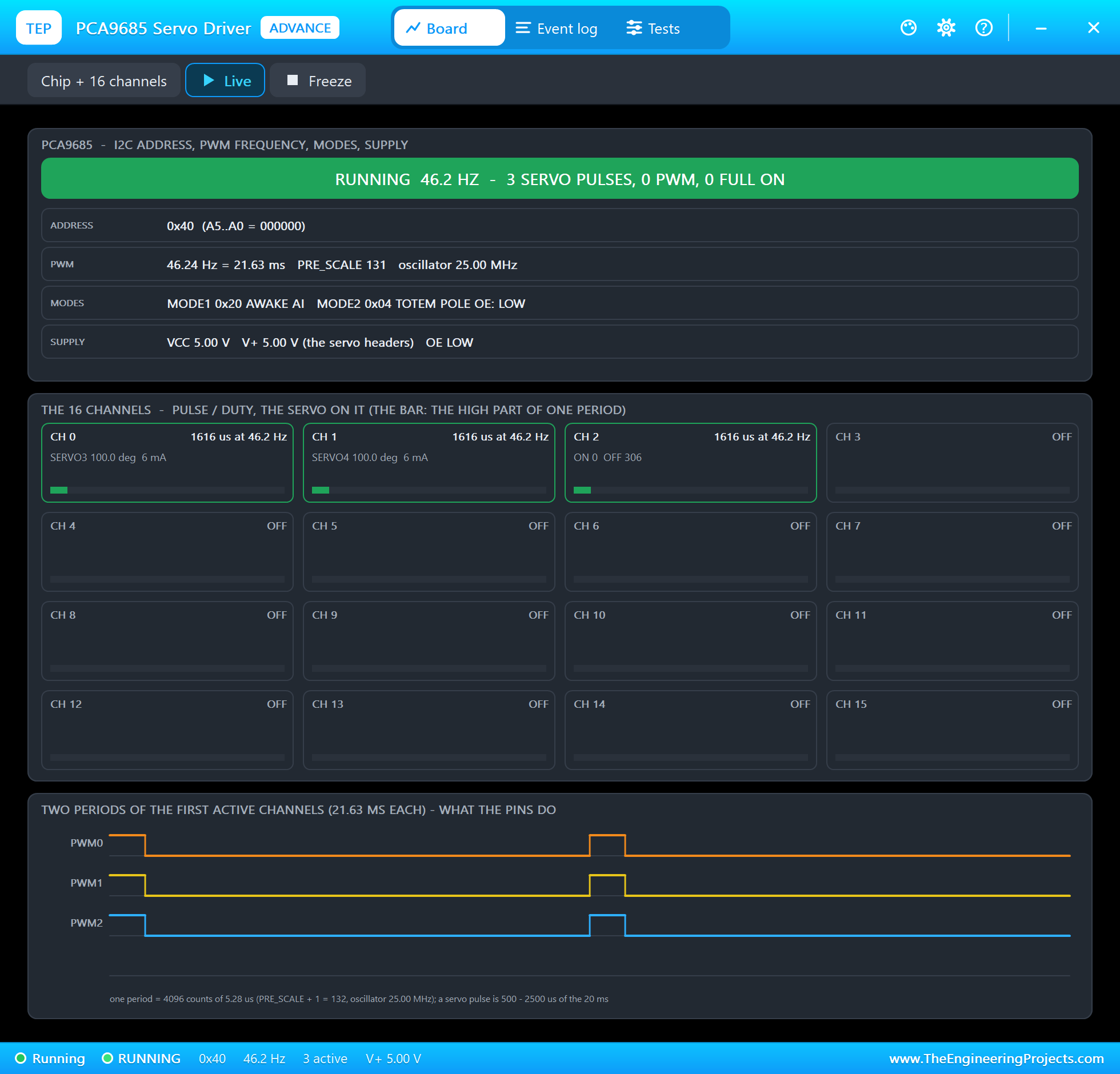
The sketch computes PRE_SCALE 131 for 27 MHz, but the chip runs 25 MHz: it makes 46.2 Hz, a period of 21.63 ms. And because writeMicroseconds() also counts with 27 MHz, every pulse is 8 percent too long: 1500 us becomes 1616 us, and SERVO3 turns to 100.4 degrees instead of 90. This is why every servo on a new board can stop a few degrees off.
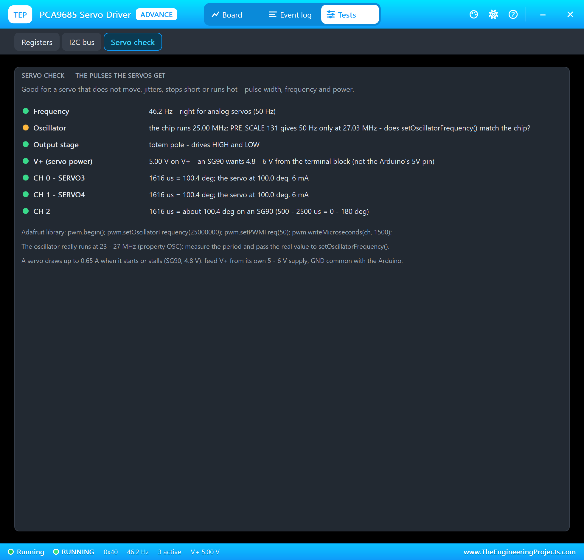
Servo check finds it: "the chip runs 25.00 MHz: PRE_SCALE 131 gives 50 Hz only at 27.03 MHz - does setOscillatorFrequency() match the chip?" On a real board, measure the period of one channel with a scope and pass the real oscillator value to setOscillatorFrequency(). In Proteus, the property OSC sets the chip's oscillator, so you can try a 23 MHz or 27 MHz chip.
Forgetting setPWMFreq(50)
begin() leaves the chip at about 1000 Hz. If a sketch forgets setPWMFreq(50), the servos get pulses a thousand times a second. Type FREQ 1000 and then DEG 0 90:
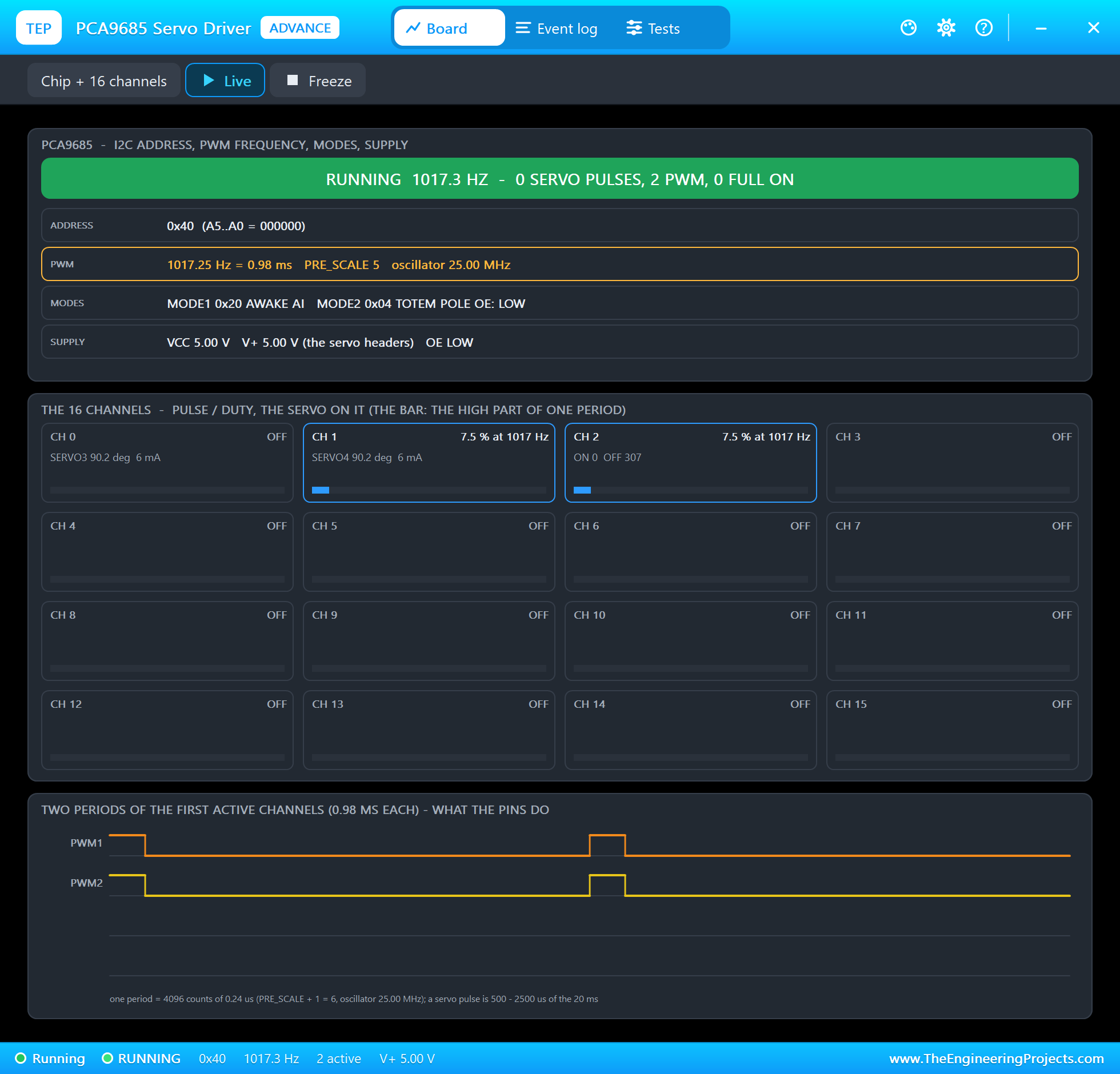
The chip runs at 1017.3 Hz (PRE_SCALE 5). The old counts, 307 on each channel, are now 7.5 percent duty: pulses of 74 us, far too short for a servo, so the servos ignore them and their horns stay where they were. And writeMicroseconds(0, 1500) at 1017 Hz asks for 6250 counts: more than 4095, and 6250 has bit 12 set, which is the full-OFF bit. CH 0 goes OFF.
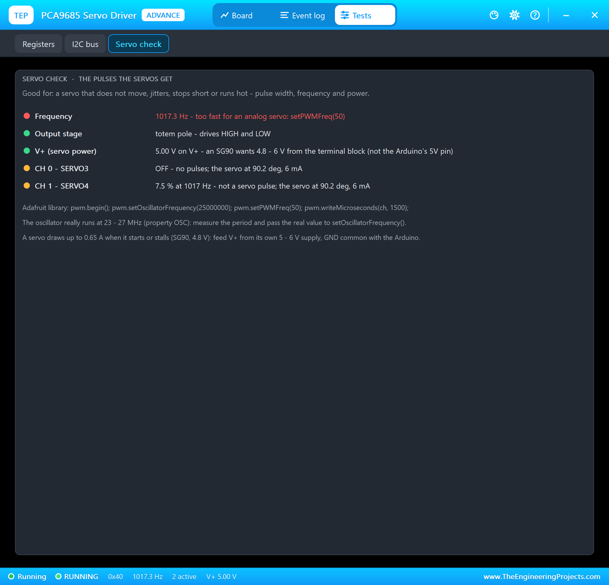
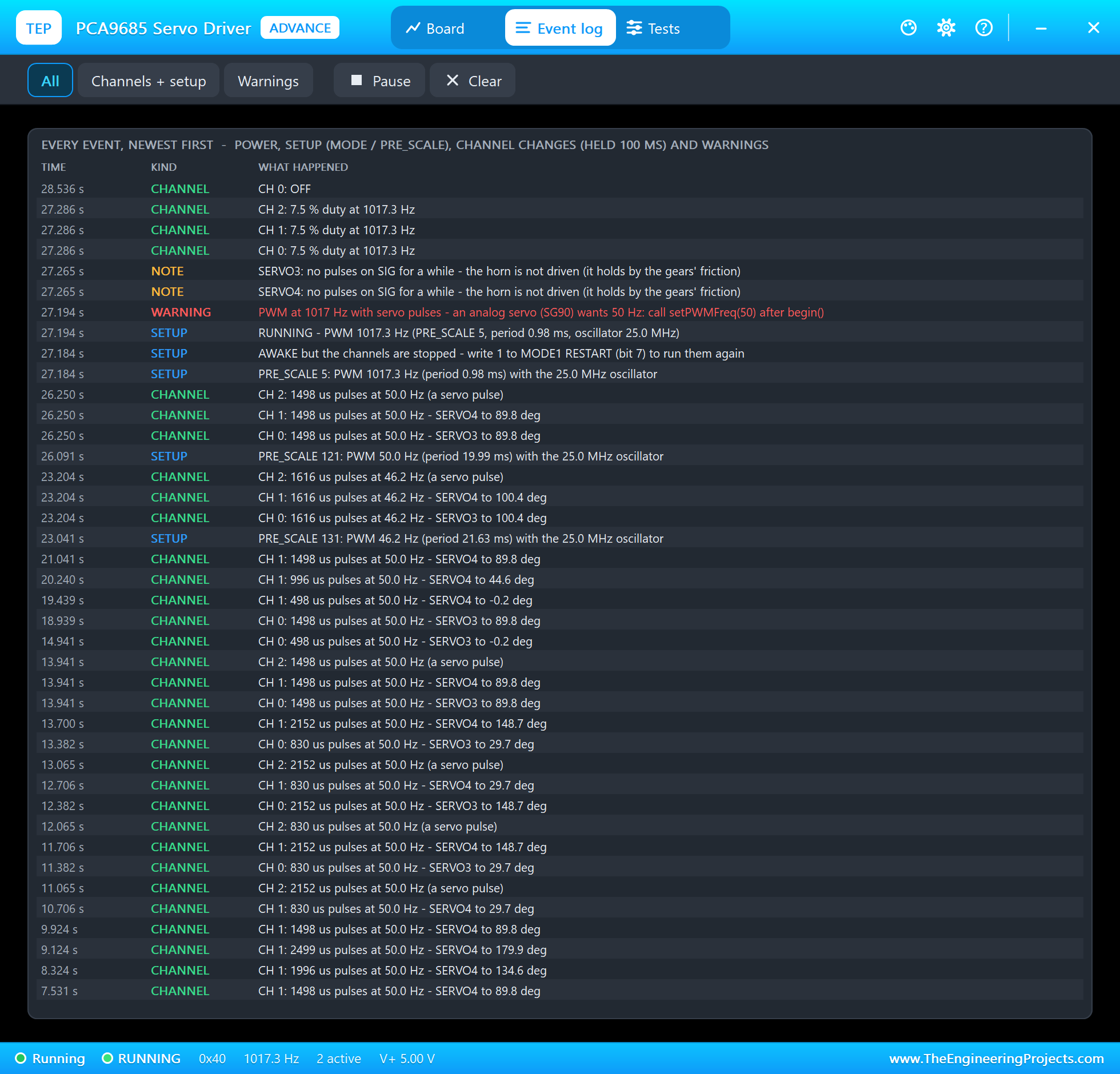
The Event log has the warning with the cure: "PWM at 1017 Hz with servo pulses - an analog servo (SG90) wants 50 Hz: call setPWMFreq(50) after begin()", and the servos add "no pulses on SIG for a while - the horn is not driven (it holds by the gears' friction)". The log also shows a detail of the datasheet: setPWMFreq() puts the running chip to sleep to write PRE_SCALE, so after the wake-up "AWAKE but the channels are stopped - write 1 to MODE1 RESTART (bit 7) to run them again", and a few milliseconds later "RUNNING", when setPWMFreq() writes RESTART after its 5 ms wait.
A Pulse Beyond the Servo's Range
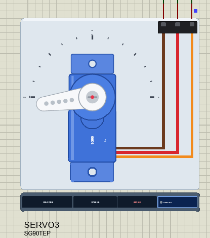
Type US 0 2800 and CH 0 gets a pulse longer than the 2500 us of 180 degrees. The horn turns as far as it can and pushes against its end stop at 188 degrees, and the motor keeps pushing: about 0.68 A, the same as a stall. The log says "SERVO3: 2796 us is beyond its range (500 - 2500 us): the horn pushes against its end stop". On a real SG90 this is the buzzing, hot servo at the end of its travel, and many SG90s reach their stop before 2500 us.
The Wrong I2C Address
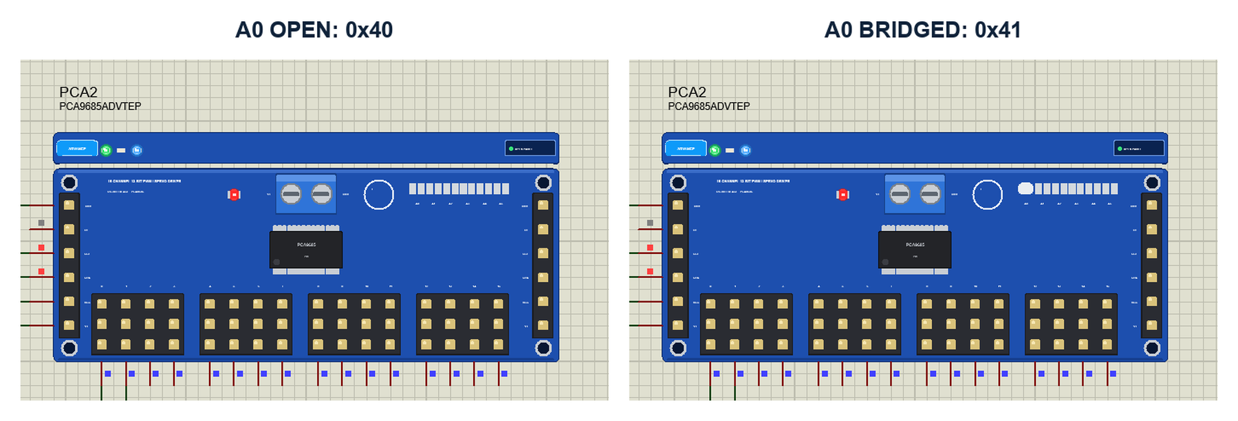
The six jumpers A0 to A5 add 1, 2, 4, 8, 16 and 32 to the base address 0x40, so up to 62 boards can share one I2C bus. A second board needs a bridged jumper, and then the sketch must use its address. In the run we clicked PCA2's A0 jumper with the mouse: "A0 jumper bridged: the board now answers 0x41". The sketch still wrote to 0x40, where nobody answered.
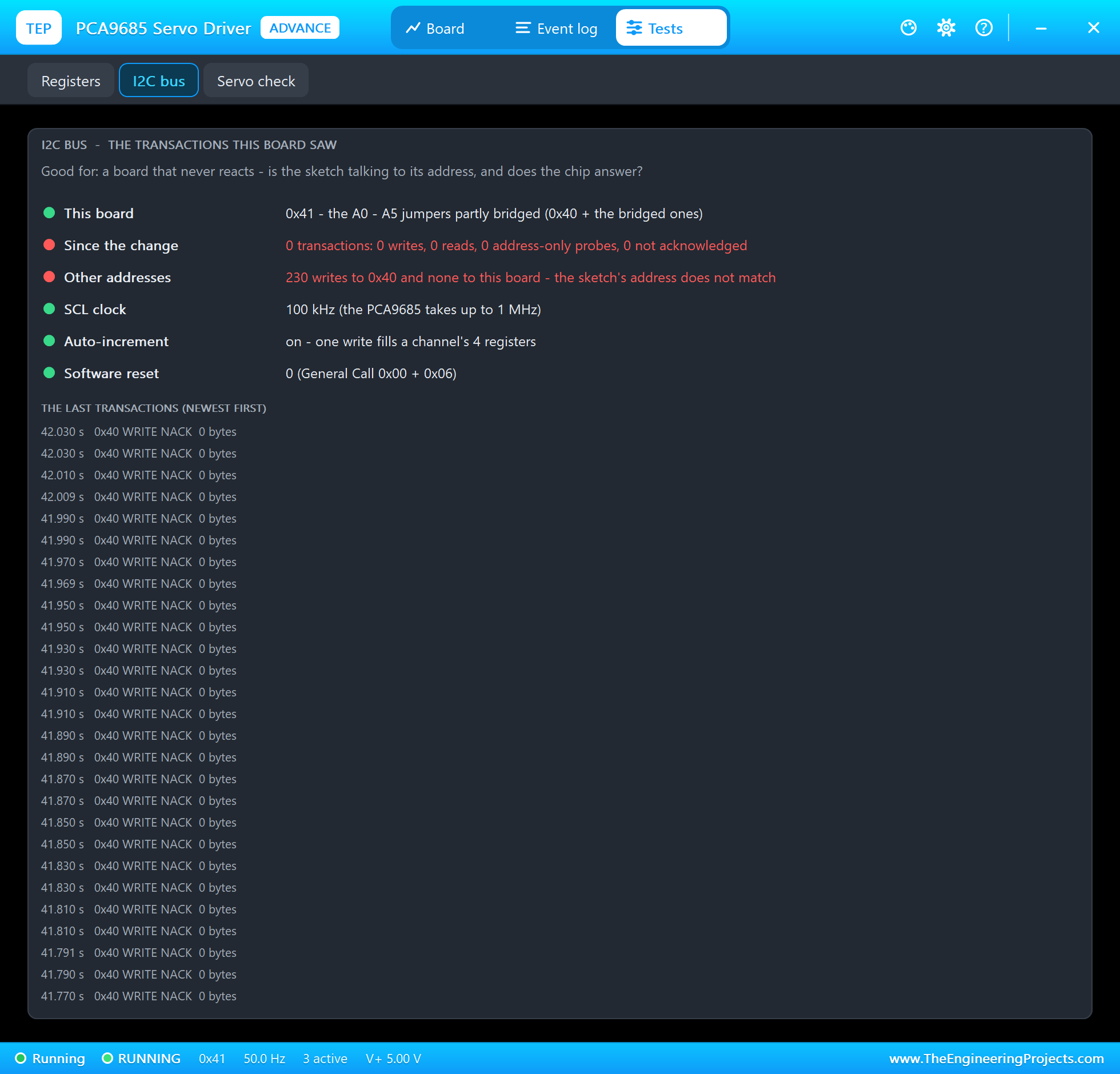
The I2C bus tool shows it at once: since the change, 230 writes to 0x40 and none to this board, in red, and the last transactions are all "0x40 WRITE NACK". The servos simply stopped following the sketch, and the sketch did not notice, because the Adafruit library does not check the answer of a write.
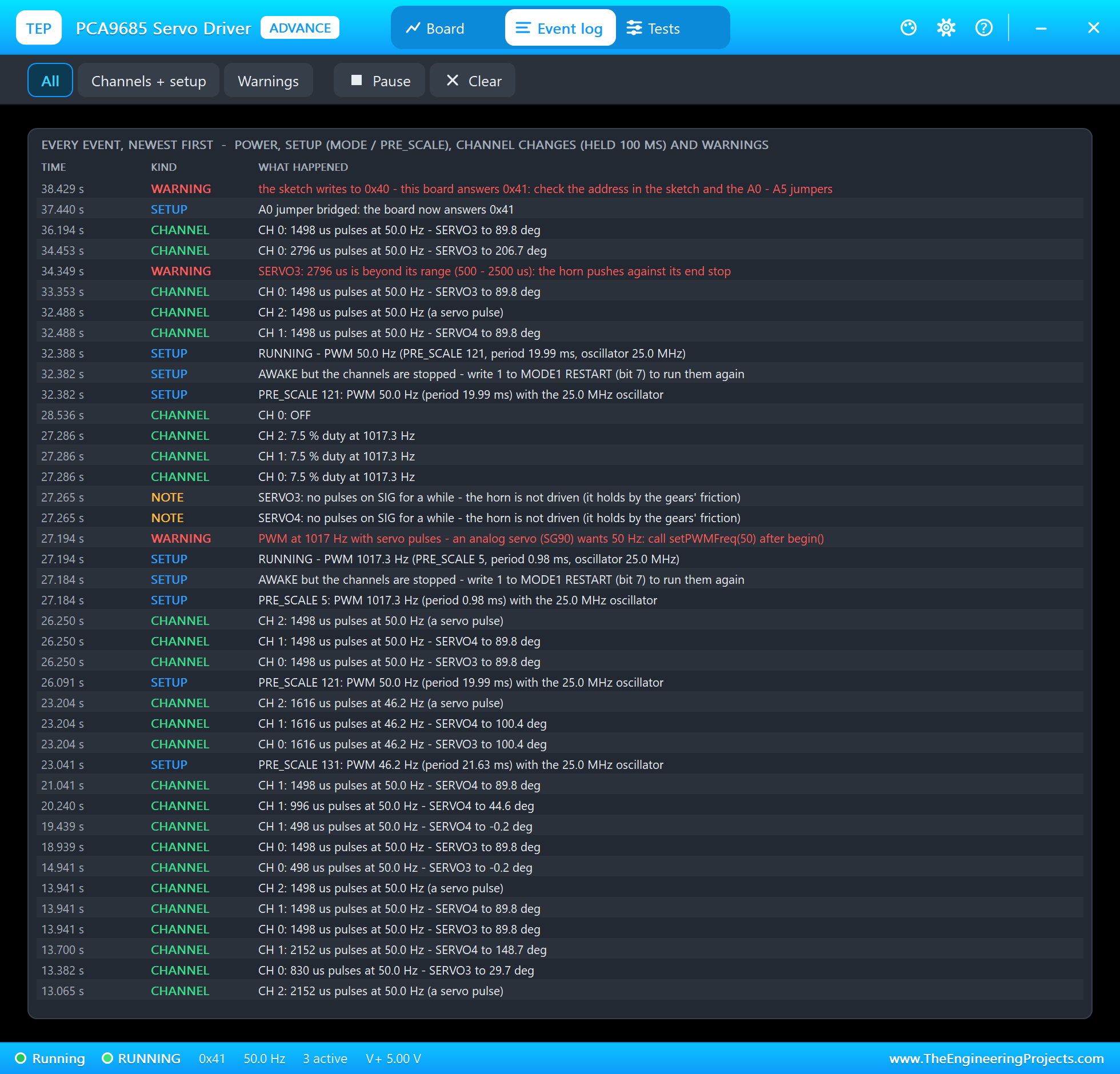
The Event log adds the warning "the sketch writes to 0x40 - this board answers 0x41: check the address in the sketch and the A0 - A5 jumpers". SCAN in the monitor confirms it:
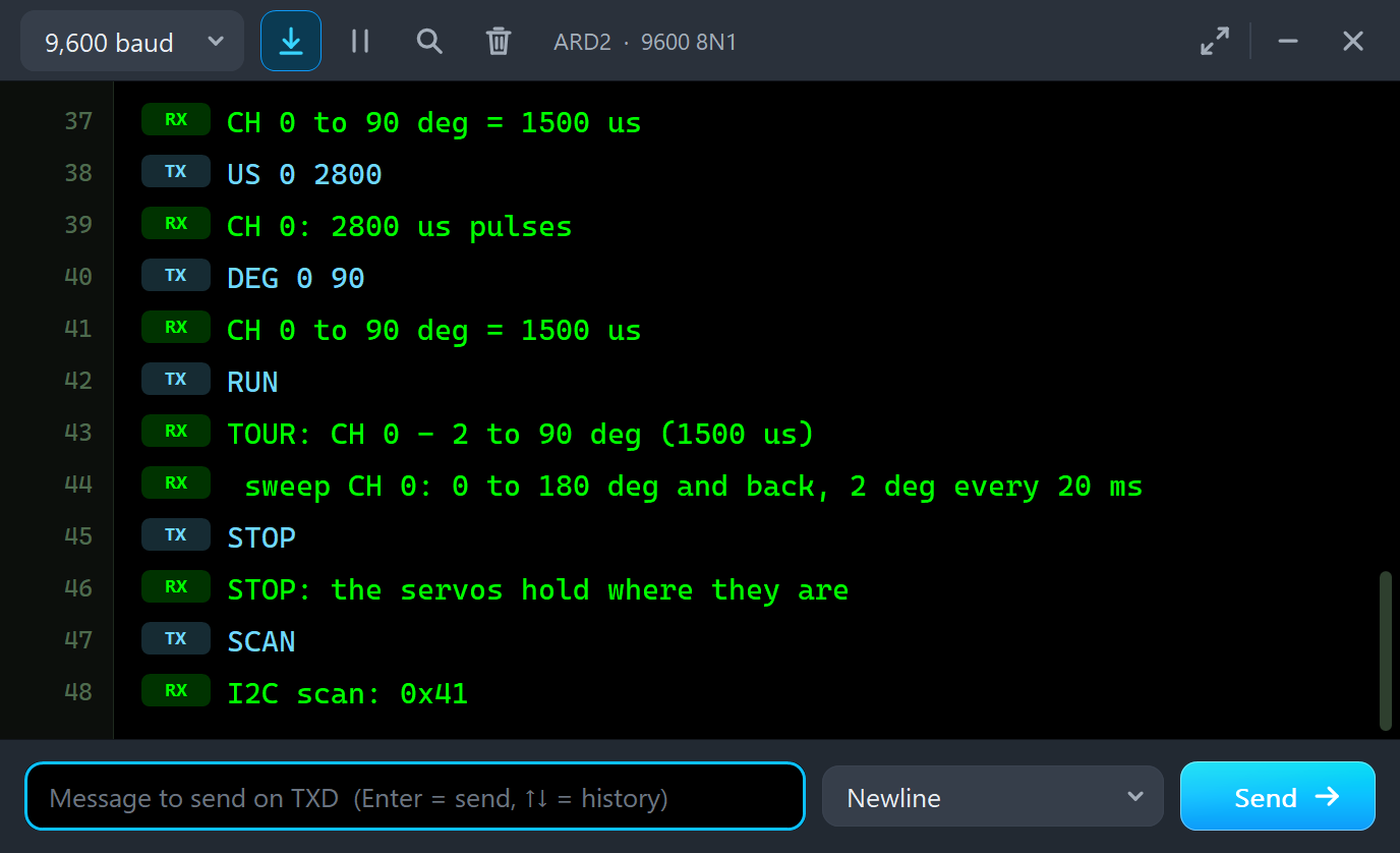
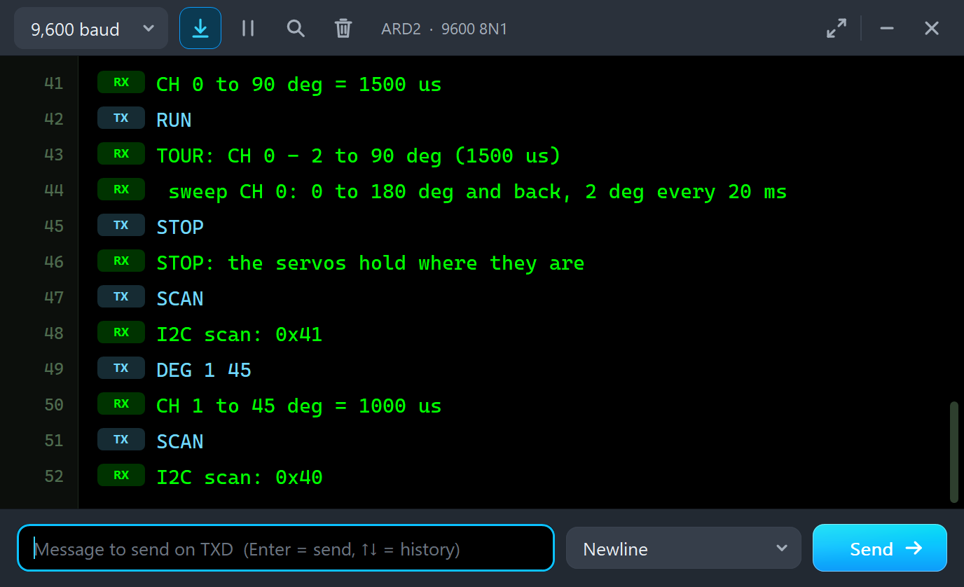
STOP
STOP: the servos hold where they are
SCAN
I2C scan: 0x41
DEG 1 45
CH 1 to 45 deg = 1000 us
SCAN
I2C scan: 0x40
Why does the scan not show 0x70 too? The ALL CALL address answers only while MODE1's ALLCALL bit is set, and begin() cleared it.
SLEEP and RESTART
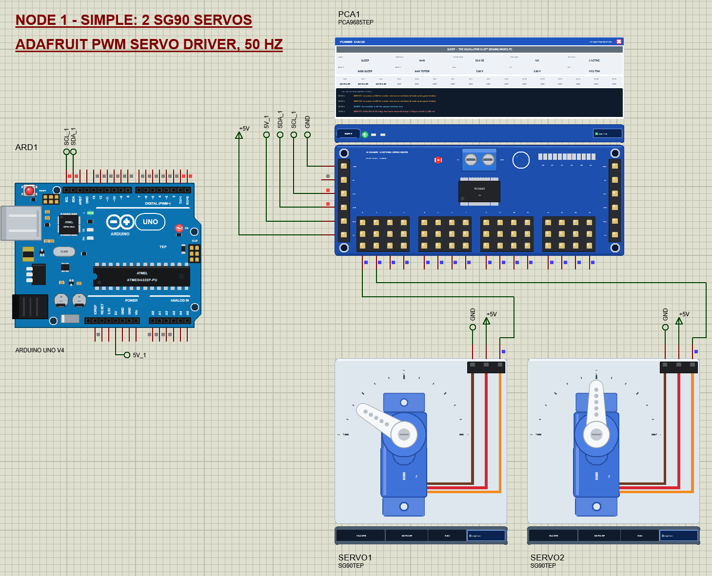
Type SLEEP on node 1: sleep() sets MODE1's SLEEP bit, the oscillator stops and the outputs hold their level. The banner turns grey, "SLEEP - THE OSCILLATOR IS OFF (BEGIN() WAKES IT)", and the servos get no more pulses. Because the channels were running when the chip went to sleep, the chip sets RESTART. The datasheet says the channels then stay stopped after a wake-up until a 1 is written to RESTART. The Adafruit wakeup() writes MODE1 back with RESTART still set, so WAKE starts the channels again, and the board logs "RUNNING - PWM 50.0 Hz".

The Simulation Log
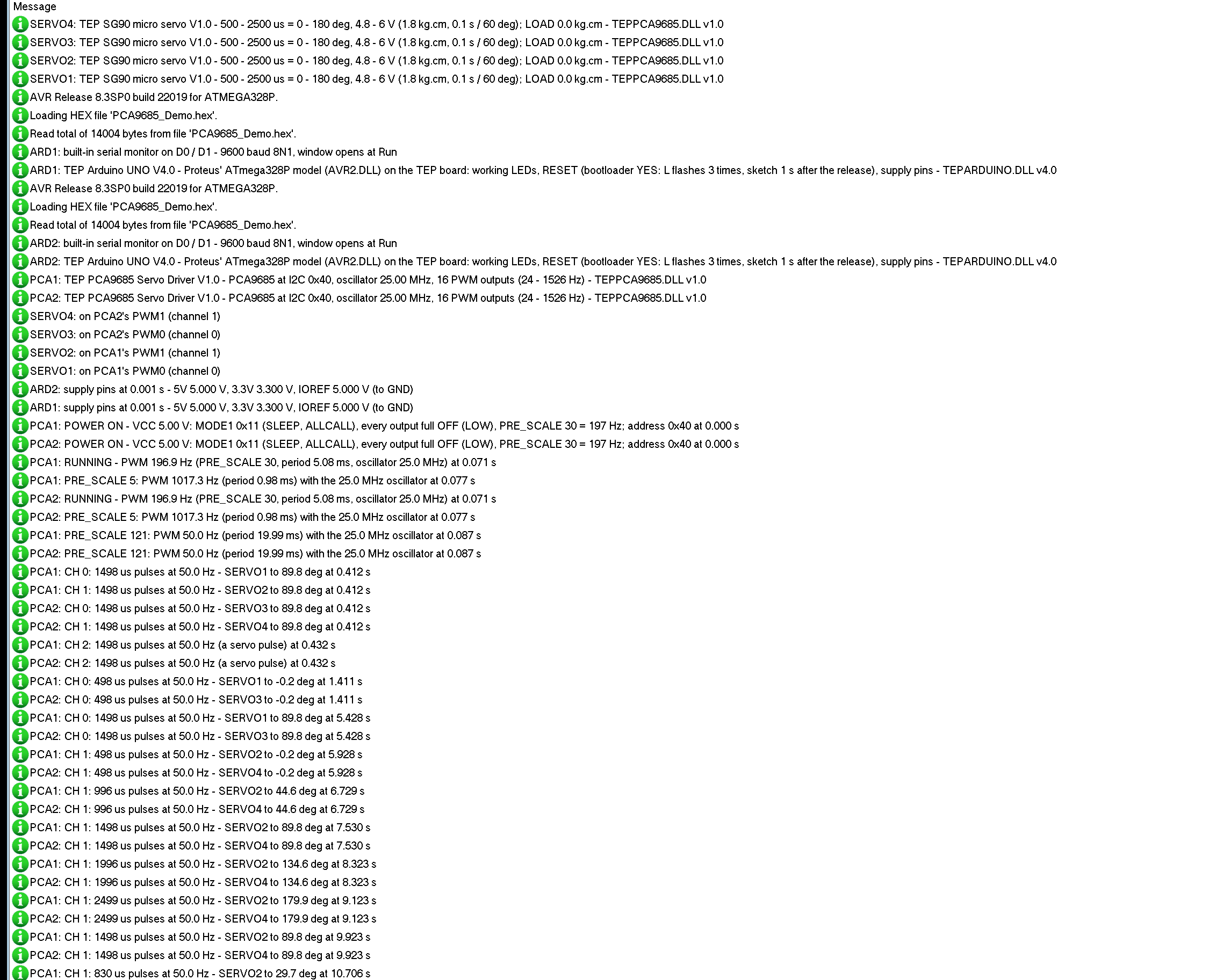
Each board writes its setup, every frequency change and the channels to the simulation log, for example "PCA1: CH 0: 1498 us pulses at 50.0 Hz - SERVO1 to 89.8 deg". Each servo writes which channel it found, and its notes: a stall, a pulse beyond its range, no pulses, no power.
How the Board and the Servo Work Together
Proteus solves the analog part of a circuit in time steps and runs the digital part, here the Arduino's I2C and the PCA9685's outputs, between them. The board decodes every I2C transaction bit by bit and answers with its own ACK and read bits on SDA. From its registers it plans the edges of each period: at the start of a period every active output goes HIGH, and at its OFF count it goes LOW. Each edge is a scheduled event at its exact time, so a 1498 us pulse is 1498 us long on the pin, not a step of the simulation.
The SG90 keeps every edge on its SIG pin with its time. It accepts a pulse of 300 to 3000 us as a servo pulse and measures the period between pulses. Over each analog step, in pieces of 1 ms or less, it integrates its motor and horn from that history: the position loop sets the motor voltage from V+, the motor current rises against its resistance and back-EMF, the torque turns the gearbox and the horn against friction, the end stops and the LOAD brake. The current goes back into the circuit, so the supply on V+ really carries it. And each servo finds the board channel on its SIG wire, so the board can show the servo's angle and current next to the channel.
Troubleshooting
- "PCA9685 at 0x40: NOT FOUND" or the board never reacts: SDA and SCL swapped or not connected, no VCC (the ON LED is dark), or the address: the sketch's address must be 0x40 plus the bridged jumpers. The I2C bus tool shows where the sketch writes.
- The channels show pulses but the servos do not move: no power on V+ (the terminal block), or the servos' GND is not common with the board's.
- The servos buzz, jump or do nothing at about 1000 Hz:
setPWMFreq(50)is missing afterbegin(). - Every servo stops a few degrees off: the oscillator. The value in
setOscillatorFrequency()does not match the chip; Servo check shows it. - A servo stops short of 0 or 180 degrees and draws current: the pulse is beyond its range, or LOAD is on.
- All outputs stay LOW after a wake-up: RESTART. With your own register writes, write 1 to MODE1 bit 7 after the wake-up; the Adafruit library does it for you.
- No part, no horn or no monitor: TEPPCA9685.DLL or TEPARDUINO.DLL is missing from MODELS and the project folder; a closed monitor opens again with a click on the UNO's USB port.
Things to Know Before Using a Real PCA9685 and SG90
- Power the servos separately: feed V+ from its own 5 - 6 V supply, with its GND joined to the Arduino's. One SG90 draws up to about 0.65 A when it starts or stalls; four of them together can reset an Arduino on USB power.
- Measure the oscillator: each PCA9685 runs at 23 - 27 MHz. For exact pulses, measure the period on a scope and pass the real value to
setOscillatorFrequency(). - Find each servo's limits: many SG90s turn less than 180 degrees for 500 - 2500 us, or reach their end stop before 2500 us. Keep the pulses inside the limits, because a servo pushing against its stop runs hot.
- One address per board: bridge A0 to A5 so that every board on the bus has its own address, and use those addresses in the sketch.
- Use the capacitor: the big capacitor on V+ helps against the current peaks of the servos; with many servos, add more capacitance near the board.
Limitations of the Simulation
- Not modelled: the I2C timing limits (any clock the AVR makes is accepted), the current limits of the outputs and their resistors, the effect of the PWR LED and the capacitor on the supply, the differences between servos, the gear play, heating and damage from a wrong supply (the models only warn).
- Digital servos (300 Hz and more) and continuous-rotation servos are not modelled; the SG90 here is the standard 180 degree analog servo.
- The strips, their LEDs, the panels, the angle scale and the LOAD button are TEP additions.
- The model is our own, written from the PCA9685 datasheet and the typical data of the SG90; it contains no code of the Adafruit libraries. This library is not made or endorsed by NXP, TowerPro, Adafruit or Labcenter.
- Licences: the demo's HEX file contains the Adafruit PWM Servo Driver library (BSD) and Adafruit BusIO (MIT), whose licence texts are in the README, and the Arduino AVR core 1.8.6 with LGPL-licensed code; its source link is in the README.
- Tested in Proteus 8.5 in October 2026 (the demo as shipped on two Arduino UNO V4.0 boards with their built-in monitors: the tour on both nodes, the LOAD button, the oscillator, 1000 Hz, the end stop, the address jumper, SLEEP and WAKE, the pop-up and the three tools; about 0.45 x real time with the pop-up and both monitors open). Proteus 7 is not supported.
So, that was all about the PCA9685 Servo Driver and SG90 Servo Motor Library for Proteus V1.0. I hope PRE_SCALE, the 12-bit counts, the oscillator and the classic mistakes are clear now, so your servos move the way you want from the first run. If you use the PCA9685 Servo Driver and SG90 Servo Motor Library for Proteus in a project, please share it in the comments or in our forum, and if you have any questions, ask in the comments and I will help you out. Till the next tutorial, take care and have fun!