Hello friends, I hope you all are doing great. Today, I am going to share the new ST7789 TFT LCD Library for Proteus V1.0. If you have bought a tiny colour screen for an Arduino project lately, there is a good chance it was one of the small blue 1.3" or 1.54" IPS TFT modules: a square 240 x 240 picture, sharp from any angle, driven over SPI by the ST7789 controller. They are cheap, bright and perfect for watches, gauges and little dashboards, and now you can design for them in Proteus before you solder a single wire.
This library is our own model of the ST7789, written from its datasheet: the 240 x 320 frame memory, the SPI interface, the rotations, the start-up waits and, most important, the habits of the IPS glass that surprise people on their first try. It covers both popular boards, the 1.3" one with 7 pins and no CS pin and the 1.54" one with 8 pins, each as a Simple device with a live STATUS panel and an Advance device with a pop-up window and four test tools. The demo runs on our Arduino UNO V4.0 with its serial monitor built into the board.
NOTICE: The 240 x 240 IPS boards are some of the most asked-about displays in our comments: why are the colours inverted, why is the picture cut off at the top, why does the board without CS stay black? We built this model to answer those questions on the screen itself, and tested it bit by bit with the real Adafruit library. It took our team a lot of hard work. Your feedback is the fuel that keeps us going, so please tell us what you think in the comments below or in the LCD Library board of our forum. And if our free libraries help you, you can buy us a coffee. So, let's get started with the ST7789 TFT LCD Library for Proteus V1.0:
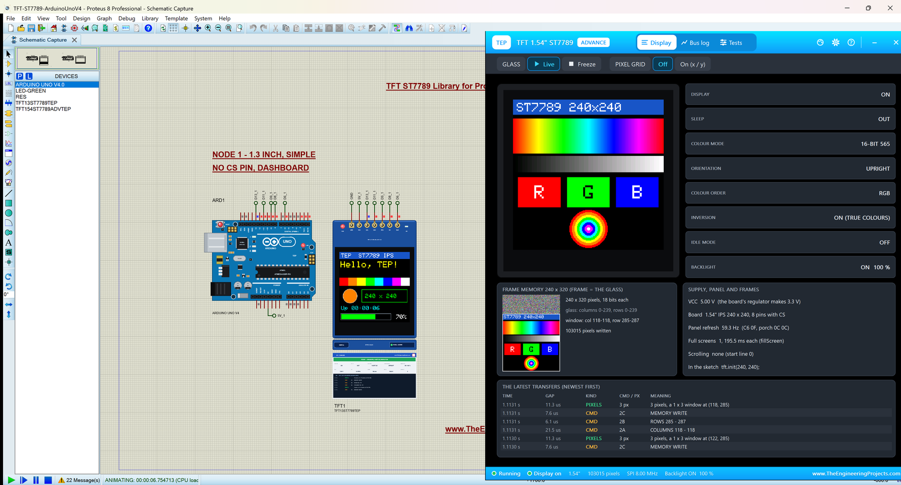
What is an ST7789 TFT LCD?
The ST7789 is a TFT controller from Sitronix. It holds a 240 x 320 frame memory of 18-bit pixels, drives the glass from it, and takes commands and pixels over a serial (SPI) or parallel interface. On the small blue modules it is wired for 4-line SPI: a clock (SCL), a data line (SDA), a data / command line (DC), a reset (RES) and, on some boards, a chip select (CS). The glass on these modules is square, 240 x 240, so it uses only part of the controller's memory.
Two boards are everywhere. They carry the same controller and the same number of pixels, but they differ in size and, more importantly, in one pin:
| 1.3" board | 1.54" board | |
|---|---|---|
| Pins | 7: GND VCC SCL SDA RES DC BLK | 8: GND VCC SCL SDA RES DC CS BLK |
| Chip select | none (tied low on the board) | CS pin |
| Board | 27.78 x 39.22 mm | 32.00 x 43.72 mm |
| Picture | 23.40 x 23.40 mm | 27.72 x 27.72 mm |
| Pixels | 240 x 240, 65K colours, IPS | 240 x 240, 65K colours, IPS |
| Devices in this library | TFT13ST7789TEP / TFT13ST7789ADVTEP | TFT154ST7789TEP / TFT154ST7789ADVTEP |
Terms You Will See in This Article
| Term | Meaning |
|---|---|
| IPS | In-plane switching: a glass that looks the same from every angle and is black when not driven |
| INVON / INVOFF | The ST7789's inversion commands 21 and 20; an IPS glass needs INVON for true colours |
| MADCTL | Command 36: the rotation (MY, MX, MV bits) and the RGB / BGR colour order |
| CASET / RASET | Commands 2A / 2B: the window of the frame memory the next pixels go into |
| SPI mode | Where the clock rests between bytes and which edge reads the data; mode 0 = clock low, rising edge |
| RGB565 | A colour in 16 bits, two bytes a pixel on the bus |
What's New in ST7789 TFT LCD Library for Proteus V1.0
- Both boards at twice their real size: the 1.3" with 7 pins and no CS, the 1.54" with 8 pins, the blue PCB, the IPS glass and the header in the module's own order.
- Our ST7789 model from the datasheet: the 240 x 320 x 18-bit memory, the command set, the four rotations, 12, 16 and 18-bit colour, inversion, idle mode, scrolling, the porch and frame-rate settings and the reset and sleep-out waits.
- The IPS glass as it really behaves: black when not driven, true colours only with INVON.
- The 80-row offset: the glass shows memory rows 0 - 239, so a picture drawn for 240 x 320 moves up and loses its top, as on a real module.
- The board without CS: every rising clock edge is a bit, and only RES brings the byte count back.
- Problems named on the panel: the black screen with its cause, inverted colours, the picture off the glass, swapped red and blue, commands too early.
- Four test tools on the Advance devices: Init check, SPI bus (with the SPI mode the sketch uses), Speed and Pixels.
- A 240 x 240 demo on our Arduino UNO V4.0 with a dashboard, a colour test and a SIZE command that shows the classic offset mistake.
- A compact package: about 1.28 MB, without the C++ source code.
Four Devices: 1.3" and 1.54", Simple and Advance
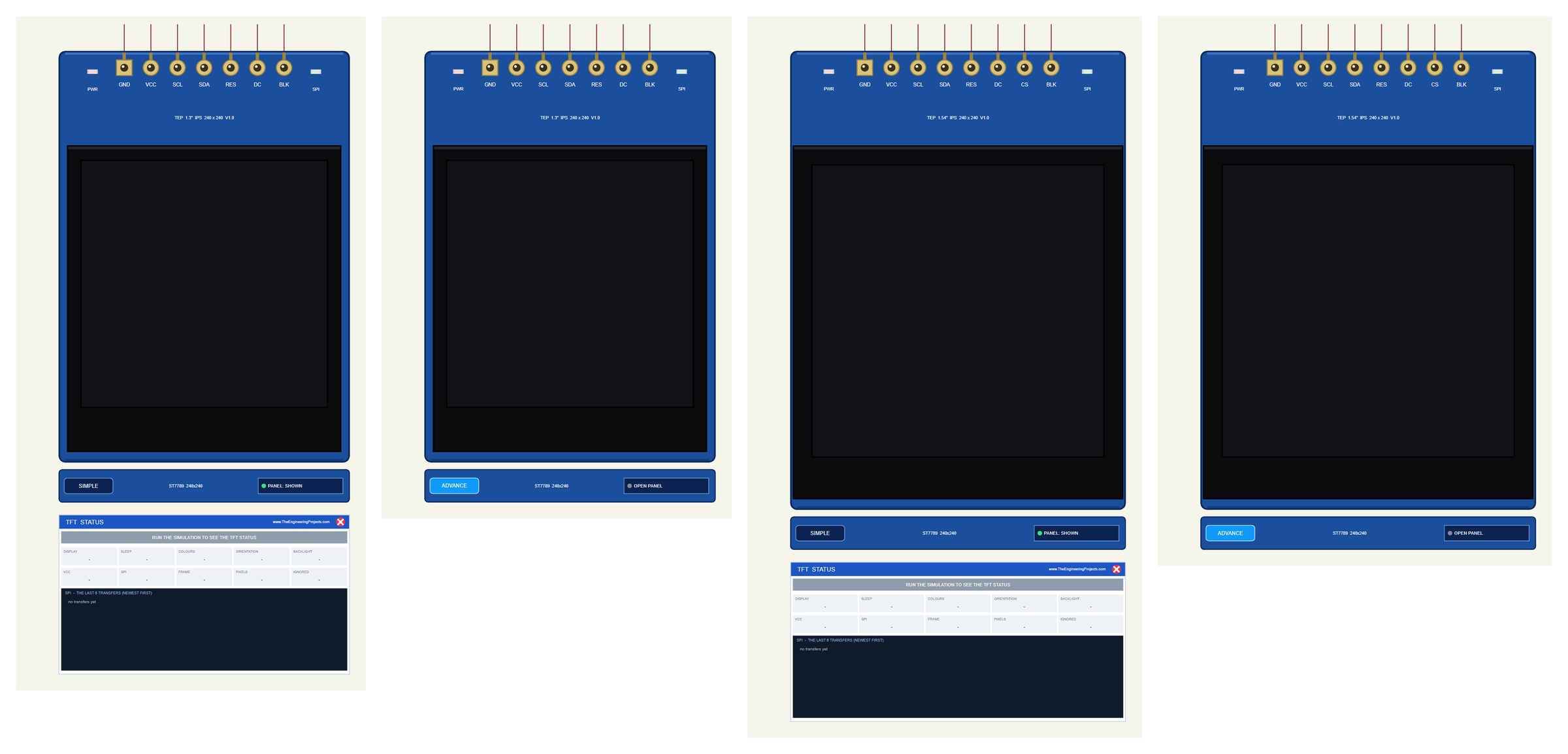
| Simple | Advance | |
|---|---|---|
| 1.3" device | TFT13ST7789TEP | TFT13ST7789ADVTEP |
| 1.54" device | TFT154ST7789TEP | TFT154ST7789ADVTEP |
| On the schematic | The board + the TFT STATUS panel | The board only |
| Status | Banner, 10 readouts, the last 6 transfers | A pop-up window: Display, Bus log, Tests |
| Test tools | - | Init check, SPI bus, Speed, Pixels |
Download ST7789 TFT LCD Library for Proteus
Click the button below to download TFT-ST7789-Library-for-Proteus-v1.0.zip (about 1.28 MB, without the C++ source code):
ST7789 TFT LCD Library for Proteus V1.0- README.txt: the devices, installation, the demo, wiring, the test tools and real hardware.
- Proteus Library Files:
TEPST7789.LIBandArduinoV4TEP.LIBfrom our Arduino Library for Proteus V4.0. - Proteus Model Files:
TEPST7789.DLLandTEPARDUINO.DLL. - Proteus Simulation:
TFT-ST7789-ArduinoUnoV4.pdsprj,TFT_ST7789_Demo.hexand copies of both DLLs. - Arduino Code:
TFT_ST7789_Demo.ino(needs "Adafruit ST7735 and ST7789 Library" with Adafruit GFX and BusIO from the Library Manager).
No Proteus yet? Read How to Download and Install Proteus 7 and 8. New to libraries? Follow How to Install a New Library in Proteus.
How to Install ST7789 TFT LCD Library for Proteus
- Close Proteus and extract the whole zip file, for example to your Desktop.
- Copy the two files from Proteus Library Files into the LIBRARY folder of Proteus (usually
C:\Program Files (x86)\Labcenter Electronics\Proteus 8 Professional\LIBRARY). - Copy
TEPST7789.DLLandTEPARDUINO.DLLfrom Proteus Model Files into the MODELS folder. - Delete
TEPST7789.IDXfrom the LIBRARY folder if there is one. - Start Proteus, press P and search for ST7789: the four devices appear.
Tip: keep the Proteus Simulation folder together, because the project needs its .hex file and the DLLs beside it. The library is tested in Proteus 8.5; Proteus 7 is not supported.
The ST7789 Boards in Proteus
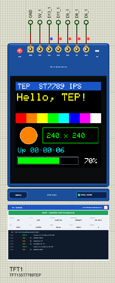
Each board is drawn at twice its real size, so the 240 x 240 pixels stay readable on a schematic. While the simulation runs, the glass shows the picture in colour and two LEDs on the board show what is going on: PWR lights with the supply and SPI flashes when a byte arrives. The strip under the board holds the SIMPLE / ADVANCE badge and the panel button. The LEDs, the strip and the panels are TEP additions; a real board has none of them.
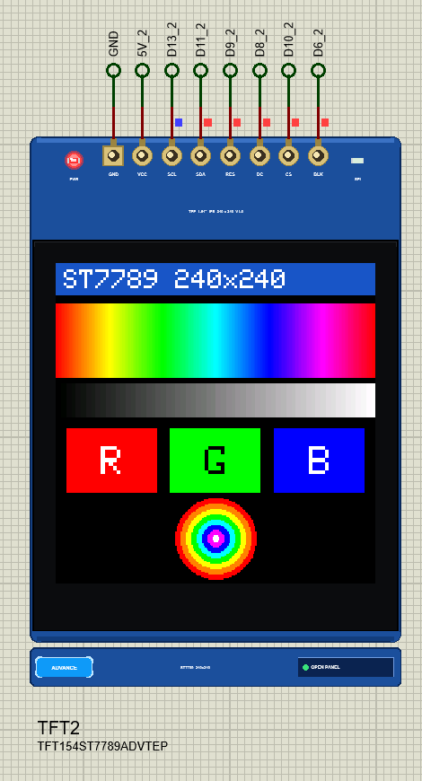
Pinout
| Pin | Function | Arduino UNO (demo) |
|---|---|---|
| GND / VCC | Ground and supply (the board's regulator makes 3.3 V) | GND / 5V |
| SCL | SPI clock | D13 (SCK) |
| SDA | SPI data in | D11 (MOSI) |
| RES | Reset, active low | D9 |
| DC | Data / command: low = command, high = data | D8 |
| CS | Chip select, active low (1.54" board only) | D10 |
| BLK | Backlight: high or open = on, PWM dims it | D6 |
| Property | Values | What it does |
|---|---|---|
| PANEL | OPEN (default), CLOSED | Simple devices only: the STATUS panel at the start |
The 1.3" Board Has No CS Pin
Look at the 1.3" board and you will find no CS. The controller's chip select is tied to ground on the board, so the ST7789 listens to every clock edge on SCL. The datasheet allows this: CSX "can be permanently grounded". The cost is that nothing marks where a byte begins. Normally CS going low restarts the bit count; without it, only a reset does. If one stray edge reaches SCL, every following byte is shifted by a bit until RES is pulsed again. Our model works exactly like that: on the 1.3" device every rising edge of SCL is a bit, and RES (or power) brings the count back to the start of a byte. Adafruit's init() pulses RES first, so the sketch always starts in step.
There is a second story around these boards: the SPI mode. Many sellers and drivers say the 7-pin boards want SPI mode 3 (the clock resting high), some say mode 2. The ST7789 itself reads SDA on the rising edge and is happy with mode 0, and that is what the model follows, while the SPI bus tool shows which mode the sketch really uses. In Proteus you have no choice anyway: the simulated ATmega328P cannot clock SPI modes 2 and 3, so the demo uses mode 0 on both boards. If a real 1.3" board stays black with mode 0, try tft.init(240, 240, SPI_MODE3); the demo keeps the mode in one line for exactly that.
#define TFT_SPI_MODE SPI_MODE0Also remember that a board without CS cannot share the SPI bus: it would read every byte meant for an SD card or a second display. If you need more than one SPI device, choose the 1.54" board with its CS pin.
240 x 240 Glass, 240 x 320 Memory: The 80-Row Offset
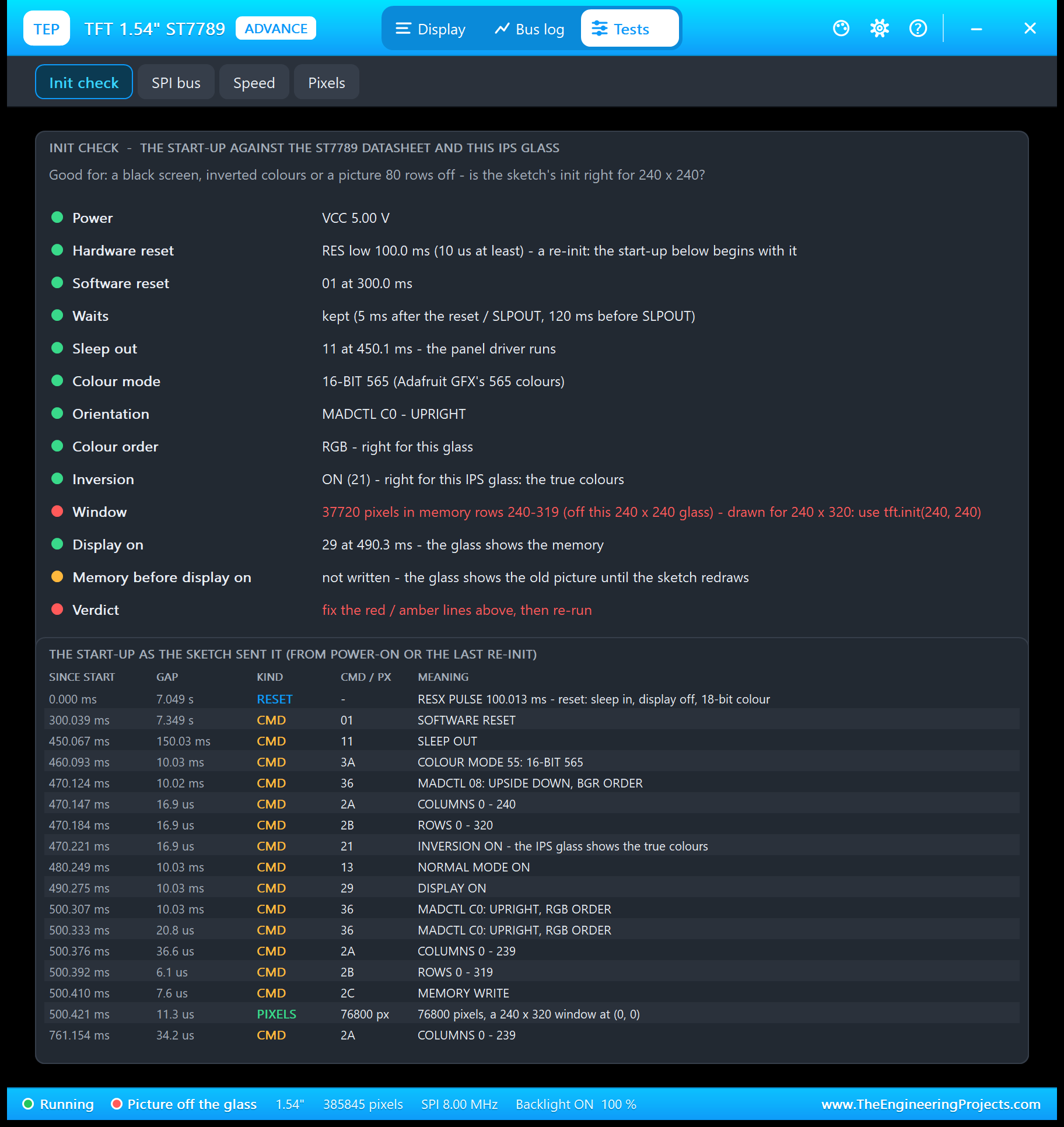
The ST7789 was designed for 240 x 320 screens, and on these modules the square glass shows only memory rows 0 to 239. That alone would be easy, but Adafruit's rotation 0 mirrors the rows (MADCTL MY), so its picture starts at row address 80 and ends at 319, which lands exactly on rows 239 down to 0. That is why tft.init(240, 240) matters: it tells the library about the offset. Our Pixels tool shows it for every pixel you click.
A sketch made for the 2.0" 240 x 320 glass, tft.init(240, 320), writes its first 80 rows into memory the square glass never shows. The demo's SIZE 320 command does exactly this on purpose:
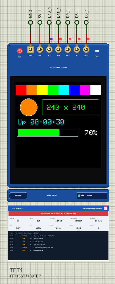
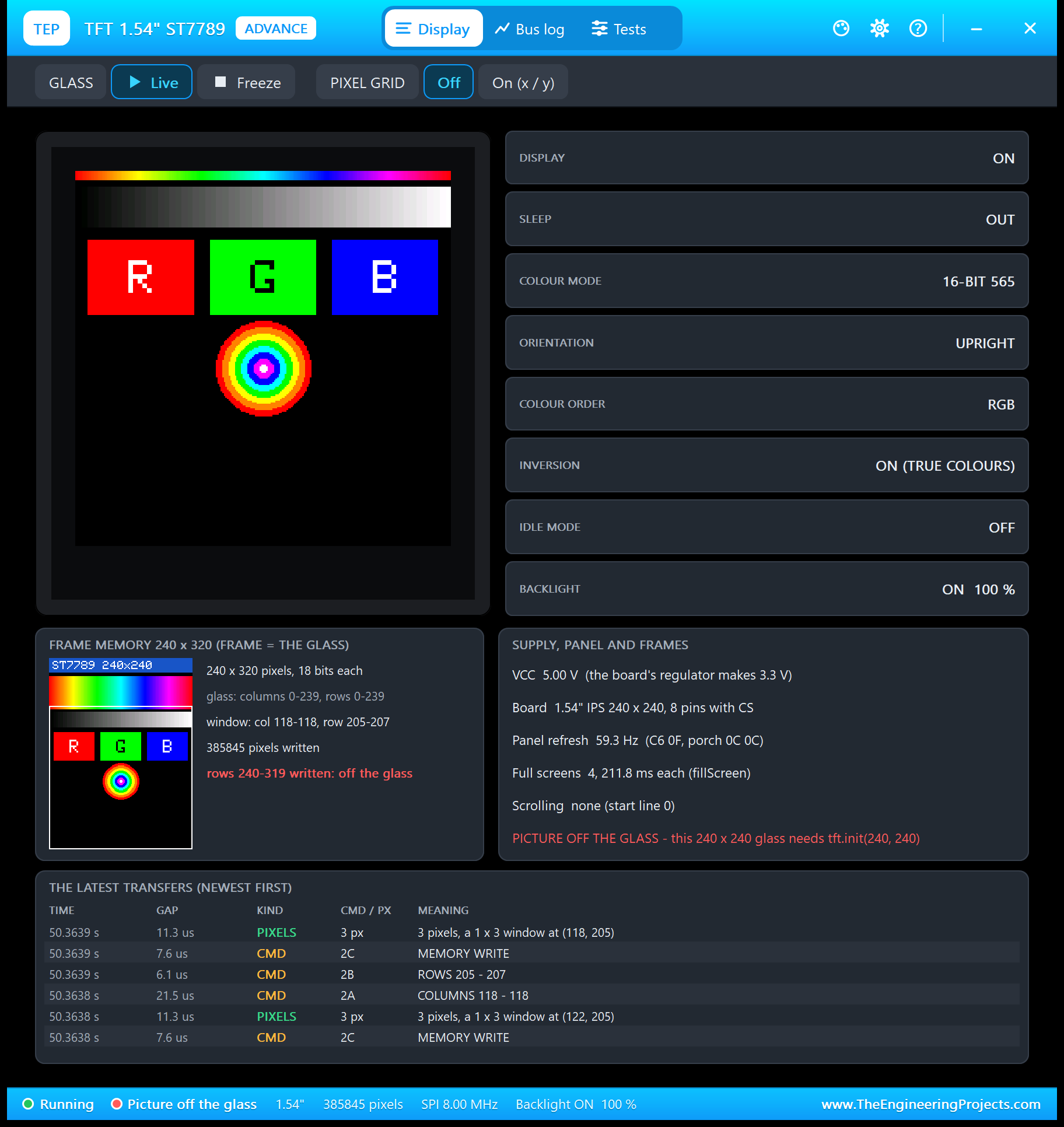
Type SIZE 240 and everything is back in place. The model counts the pixels that go to rows 240 - 319 and raises the warning only for those, so rotations 1, 2 and 3, which Adafruit offsets differently, stay green.
Why Are My ST7789 Colours Inverted?
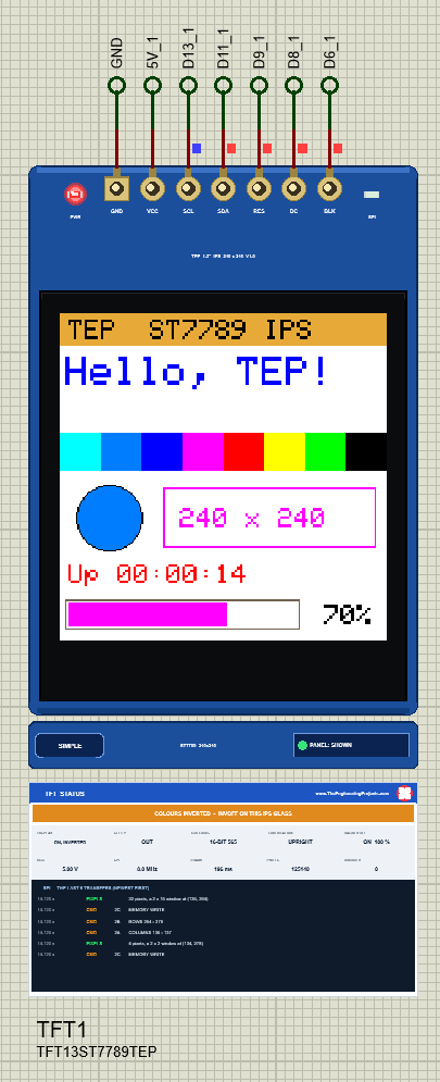
The ST7789's reset state suits a classic TN glass. An IPS glass works the other way round, so on these modules the picture is only right with the controller's inversion ON. Every ST7789 start-up therefore sends INVON (21), and Adafruit's does too. The trap is invertDisplay(): on an IPS glass invertDisplay(true) gives the true colours, and invertDisplay(false) inverts them. The demo turns this around for you:
tft.invertDisplay(!inverted); // an IPS glass shows the true colours with the controller's inversion ONThe model reproduces the glass, not a rule: the frame memory keeps the right colours, and only what reaches the glass is inverted. The Display page shows INVERSION ON (TRUE COLOURS) or OFF - INVERTED, and the Init check flags a missing INVON in red.
The Black Screen
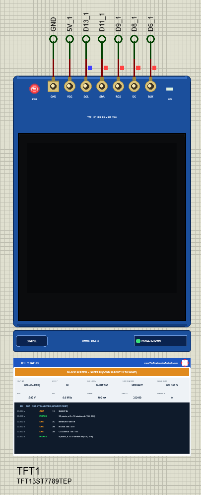
Another IPS habit: a glass that is not driven is black, not white. Before the sketch starts, while it sleeps, while the display is off, and when nothing reaches the controller at all, you see a dark square with the backlight glowing behind it. On the bench that is hard to tell apart from a dead board, which is why the STATUS panel names the reason: NOTHING ON SPI YET, STILL IN SLEEP, SLEEP IN, DISPLAY OFF, or STILL ASLEEP when SLEEP OUT came too soon after a reset.
Backlight and Rotation
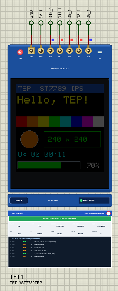
BLK switches the backlight through a transistor on the board. Most boards pull it up, so an open BLK pin means a lit screen; the model does the same. Wired to a PWM pin, it dims:
analogWrite(TFT_BLK, light); // the backlight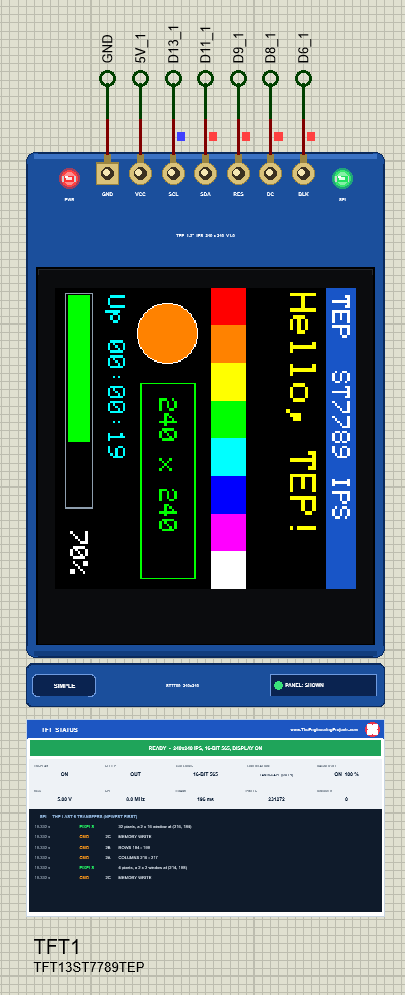
On a square glass every rotation is 240 x 240, so the demo's layout fits all four. Behind the scenes Adafruit moves the 80-row offset to the axis that addresses the rows, which is why rotations 0 and 1 use addresses up to 319 and the model still lands every pixel on the glass.
ST7789 Simple: The STATUS Panel
Under the Simple devices a live TFT STATUS panel shows the banner (READY, or the problem in amber or red), ten readouts - DISPLAY, SLEEP, COLOURS, ORIENTATION, BACKLIGHT, VCC, SPI, FRAME, PIXELS and IGNORED - and the last six transfers. FRAME is the time of the last full screen on the bus; IGNORED counts bytes the controller threw away (too early, unknown, during reset, cut by CS). The red X closes the panel; PANEL on the strip opens it again.
ST7789 Advance: The Pop-Up Window
The Advance devices keep only the board on the schematic; at Run they open a pop-up window with three pages and the look of our serial monitor.
The Display Page
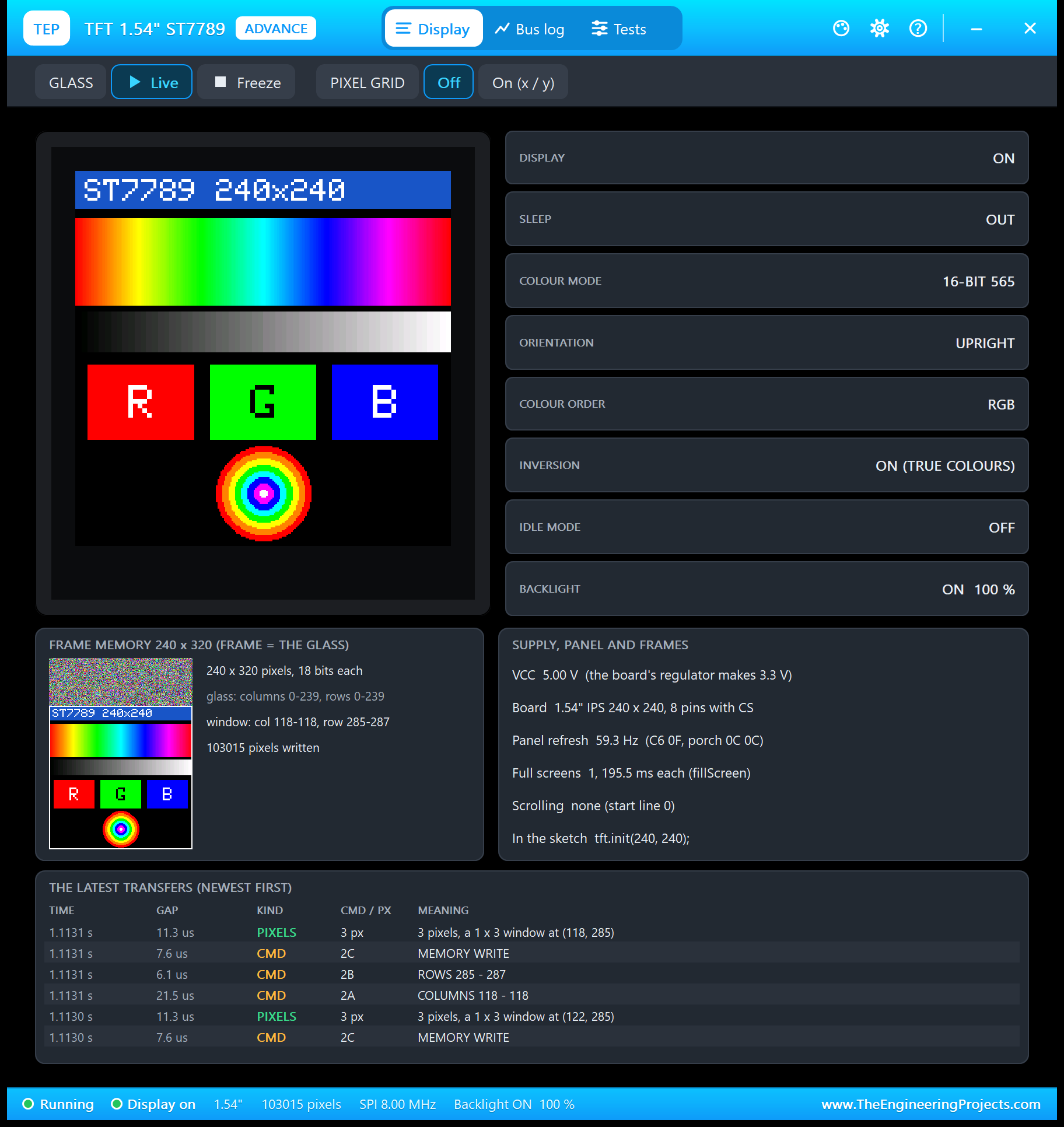
The tiles read the controller: display, sleep, colour mode, orientation, colour order, inversion, idle mode and the backlight. The frame memory card is mirrored like the glass, so the 80 rows the glass does not show sit on top, still full of the random pixels of power-on. GLASS Freeze holds the picture, and PIXEL GRID draws a grid with x / y numbers.
The Bus Log Page
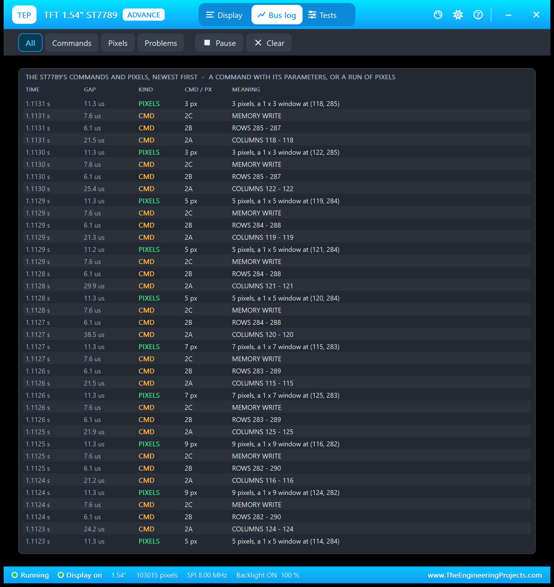
Each line gives the time, the gap to the previous byte, the kind, the command byte or pixel count and its meaning. The filters show only commands, only pixels or only problems; Pause freezes the list.
Four Test Tools for the ST7789
1. Init Check
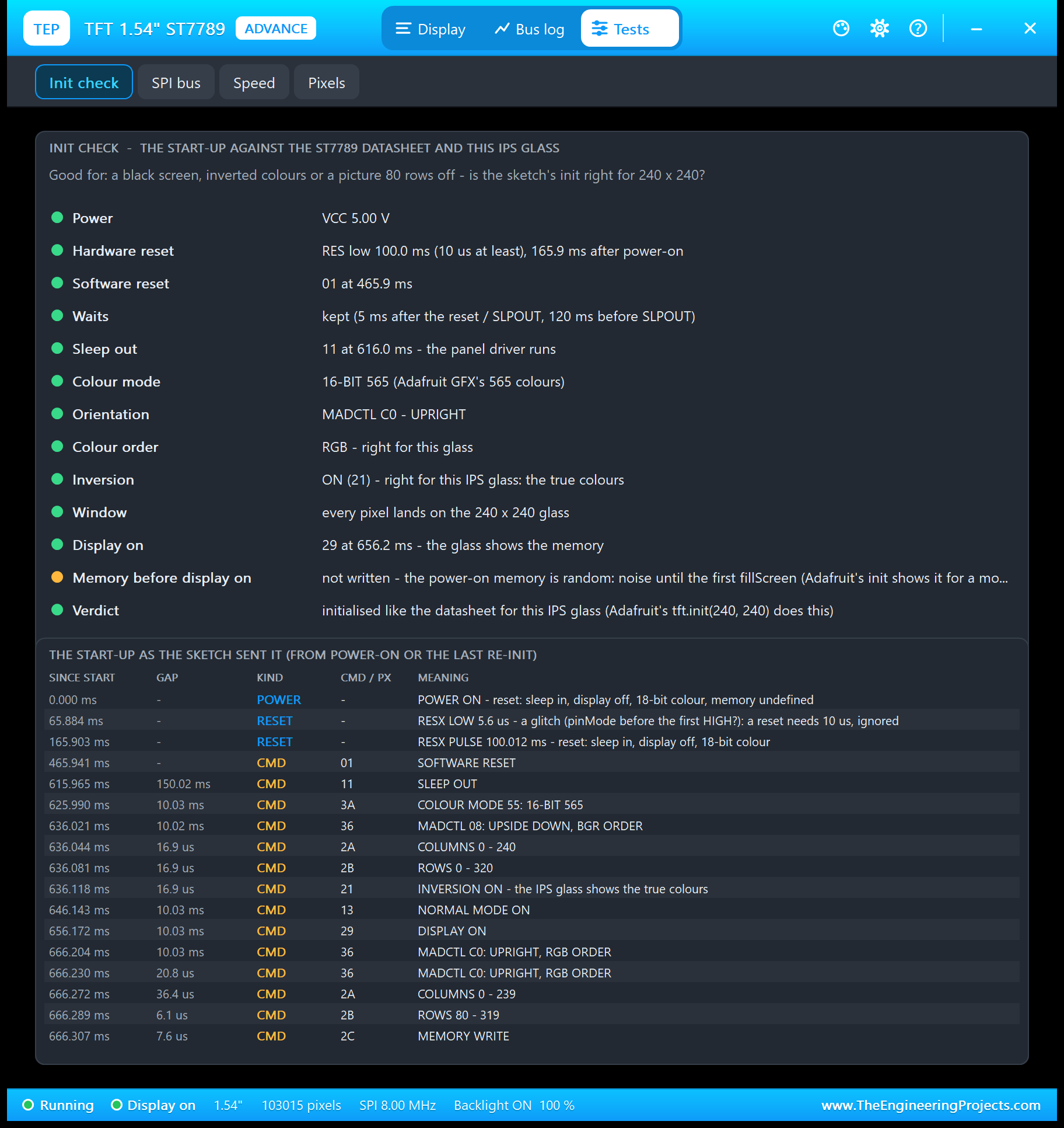
The start-up against the ST7789 datasheet and this glass: the supply, the hardware reset with its length, SWRESET, the waits (5 ms after a reset or SLEEP OUT, 120 ms after a reset before SLEEP OUT), the colour mode, MADCTL, the colour order, the inversion, the window and DISPLAY ON, then the start-up as the sketch sent it. One amber note is normal: Adafruit switches the display on before the first fillScreen, so the random power-on memory shows for a moment. The log also shows a RES glitch of 5.6 us, the moment the UNO's pin turns into an output; the ST7789 ignores pulses that short, and so does the model.
2. SPI Bus
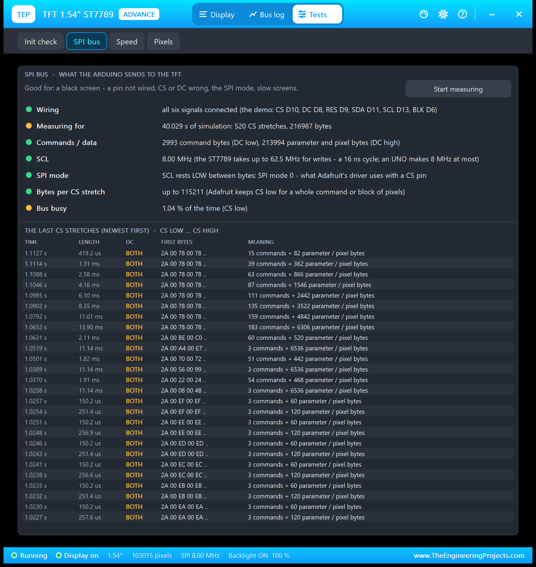
Good for a black screen: which pins are wired (five on the 1.3", six on the 1.54"), the command and data bytes, the clock (the ST7789 takes up to 62.5 MHz for writes, an UNO makes 8 MHz), the SPI mode the sketch really uses, cut bytes, clocks with CS high, bytes during reset and commands too early. On the 1.3" board, which has no CS stretches, the list groups the bus by commands instead.
3. Speed
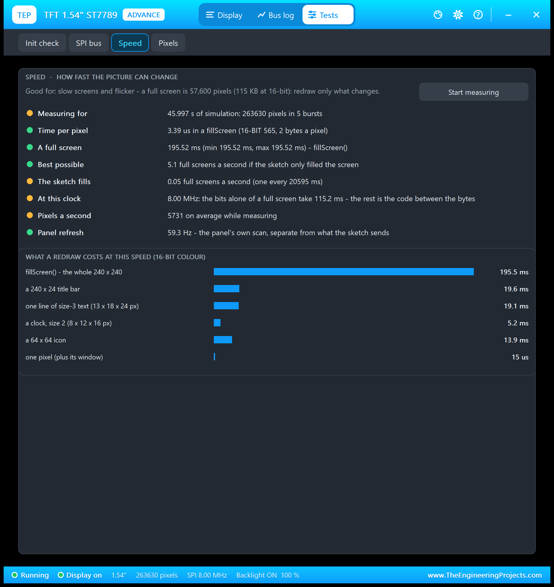
A full screen is 57,600 pixels, 115,200 bytes. At the UNO's 8 MHz the bits alone take 115 ms; Adafruit's loop between the bytes brings a fillScreen to about 195.5 ms, 3.39 us a pixel. The table makes the design rule plain: a title bar costs about 20 ms, a clock about 5 ms, a full screen a fifth of a second. Redraw what changes.
4. Pixels
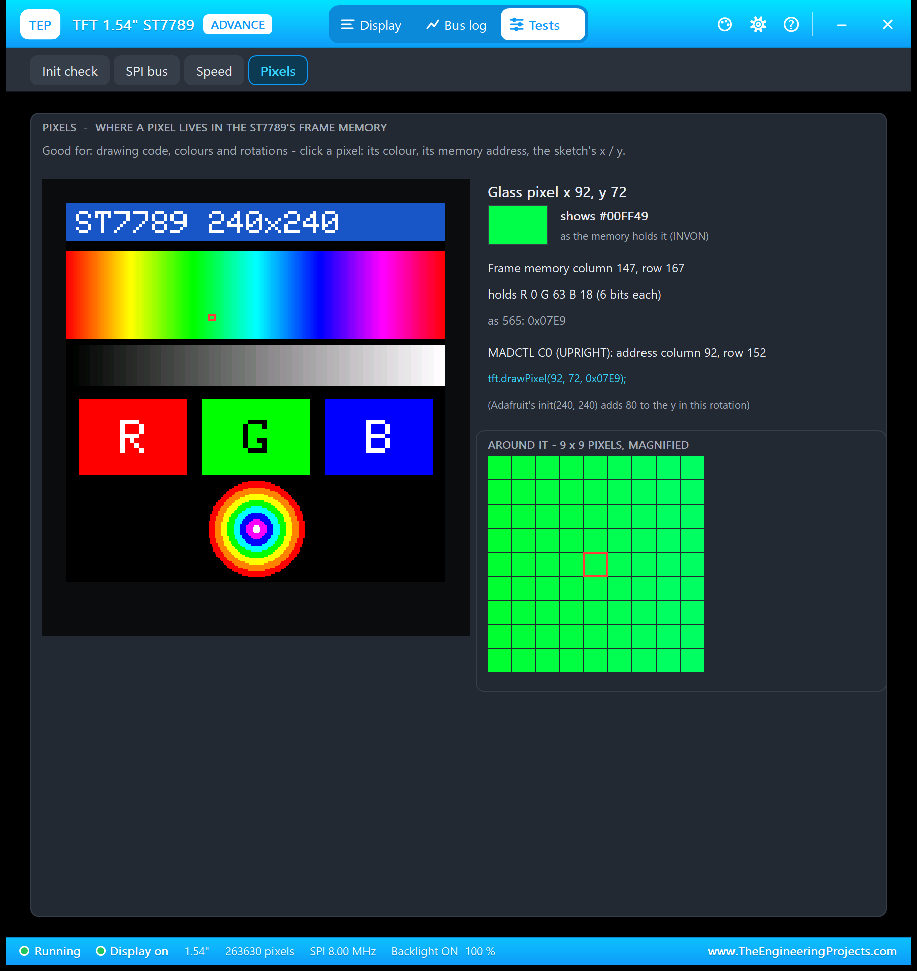
Click any pixel to see its colour, where it lives in the 240 x 320 memory, the 18 bits it holds, its RGB565 value, the CASET / RASET address in the current rotation and the drawPixel() line that writes it, with the neighbours magnified. It is the quickest way to understand the offset and the rotations.
ST7789 TFT LCD with Arduino in Proteus
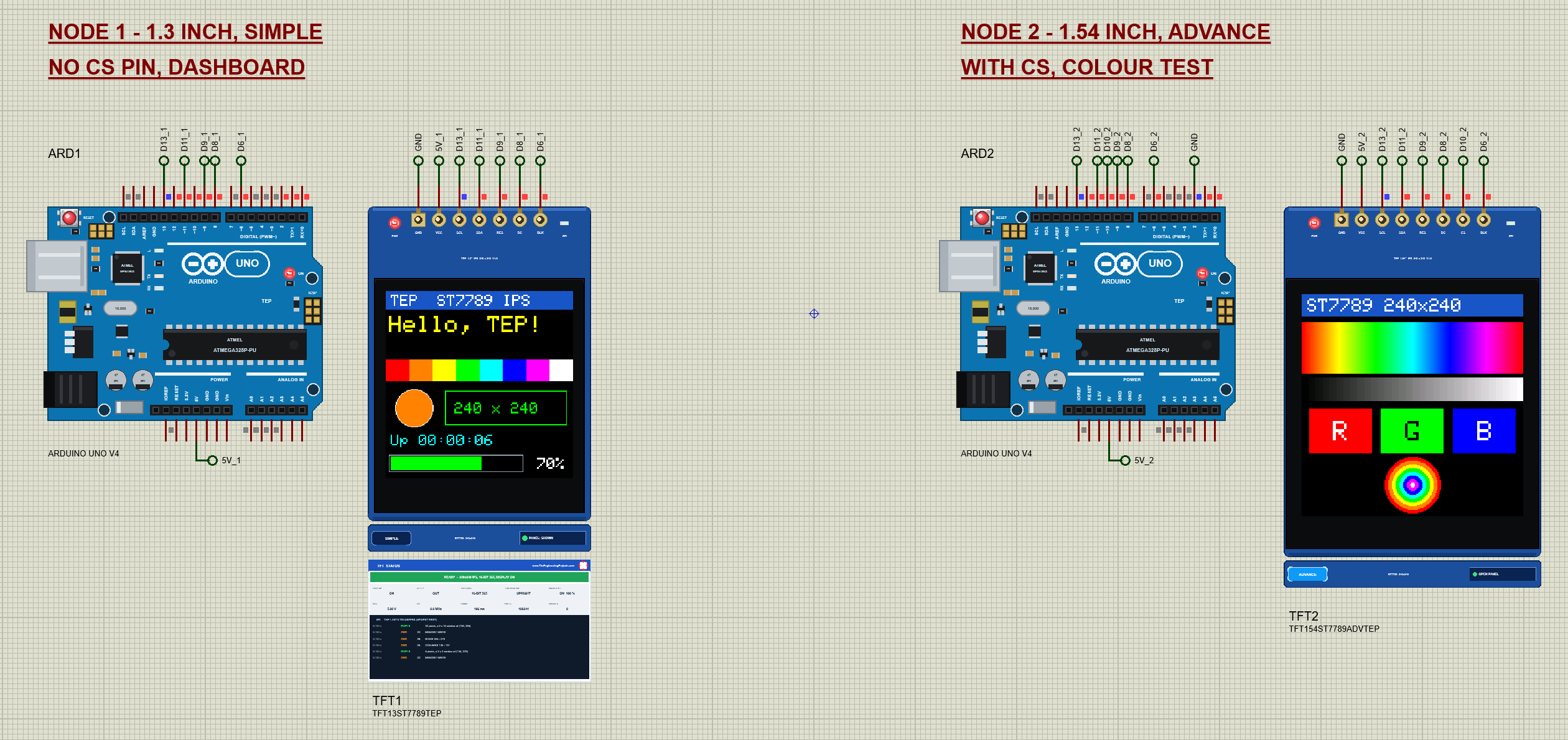
Open TFT-ST7789-ArduinoUnoV4.pdsprj. Two Arduino UNO V4.0 boards from our Arduino UNO Library for Proteus V4.0 run the same sketch; ARD2's D2 is tied to GND, so it starts with the colour test. The monitors are built into the boards, and our Introduction to Arduino UNO explains the pins.
Wiring
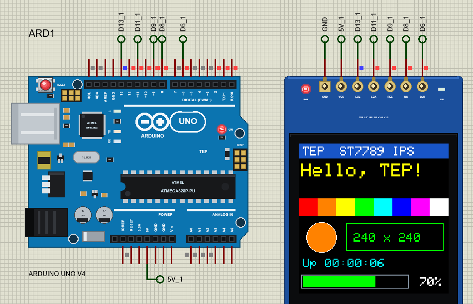
SCL goes to D13 and SDA to D11, the UNO's hardware SPI pins. RES, DC, CS and BLK can use any pin; the demo uses D9, D8, D10 and D6 (a PWM pin for the backlight). On the 1.3" board D10 stays free: Adafruit still toggles it, but there is nothing to connect.
The Arduino Code
The sketch uses the Adafruit ST7735 and ST7789 library 1.11.0 and the Adafruit GFX library 1.12.6:
#include <SPI.h>
#include <Adafruit_GFX.h>
#include <Adafruit_ST7789.h>
The pins and the object, on hardware SPI:
const byte TFT_CS = 10, TFT_DC = 8, TFT_RST = 9, TFT_BLK = 6, SCREEN_PIN = 2;Adafruit_ST7789 tft(TFT_CS, TFT_DC, TFT_RST); // hardware SPI: SDA = D11, SCL = D13The start-up. The second number is the glass height, the only place where the 80-row offset is decided:
void initTft() {
  tft.init(240, tall, TFT_SPI_MODE);             // 240 x 240: the 1.3" and 1.54" glass (320 = the wrong size, for the SIZE test)
  tft.setRotation(rotation);
The clock is redrawn every second with a background colour, so the new digits cover the old ones without a fillRect:
tft.setTextColor(CYAN, BLACK); // with a background colour: the new digits overwrite the old onesThe bar redraws only the part that changed:
  if (filled > was) tft.fillRect(6 + was, y + 2, filled - was, 18, GREEN);
  else if (filled < was) tft.fillRect(6 + filled, y + 2, was - filled, 18, BLACK);
The colour test's hue sweep computes with a long, because 239 x 1536 does not fit the UNO's 16-bit int:
const int h = (long)x * 1536 / w; // 0..1535: six 256-step segments round the colour wheelAnd FILL times a full screen:
    const unsigned long t0 = millis();
    tft.fillScreen(BLUE);
    fillMs = millis() - t0;
To change the sketch, export a new HEX and load it into the UNO; see How to get the HEX file from Arduino. New to Arduino? Start with our Arduino Tutorial for Beginners.
Serial Monitor Commands
| Command | What it does |
|---|---|
| HELP / STATUS | The command list / the size, rotation, screen, text, bar, backlight and the last fill time |
| TEXT <text> / BAR <0-100> | The big text / the bar (only its changed part is drawn) |
| LIGHT <0-255> | The backlight on D6 (PWM) |
| DASH / TEST / CLEAR | The dashboard / the colour test / a black screen |
| FILL | A timed fillScreen of the whole 240 x 240 glass |
| ROTATE <0-3> | setRotation(): the four orientations |
| INVERT ON / OFF | Inverted / true colours (invertDisplay(false) / (true) on IPS) |
| SLEEP / WAKE, DISPLAY ON / OFF | Sleep in / out; display on / off: the glass goes black |
| SIZE 240 / SIZE 320 | tft.init(240, 240) (right) or tft.init(240, 320) (the offset mistake) |
How to Run the Demo
- Press Run; move the monitor windows and TFT2's pop-up aside.
- In ARD1's monitor type STATUS, TEXT Hi TEP, BAR 25, LIGHT 60, INVERT ON, ROTATE 1 and SLEEP / WAKE.
- Try SIZE 320 and watch the picture move, then SIZE 240.
- On TFT2 open Tests: Init check, SPI bus, then FILL in ARD2's monitor and Speed, then Pixels and click a pixel.
ST7789 TFT LCD Proteus Simulation Results
The Built-in Serial Monitor in Its Simple Interface
Each Arduino UNO V4.0 carries our TEP Serial Monitor Advance, wired inside the board to D0 / D1. The screenshots show its Simple interface (Ctrl+Shift+U; Esc for the full view). Read all about it in TEP Serial Monitor Advance for Proteus.
ARD1: STATUS
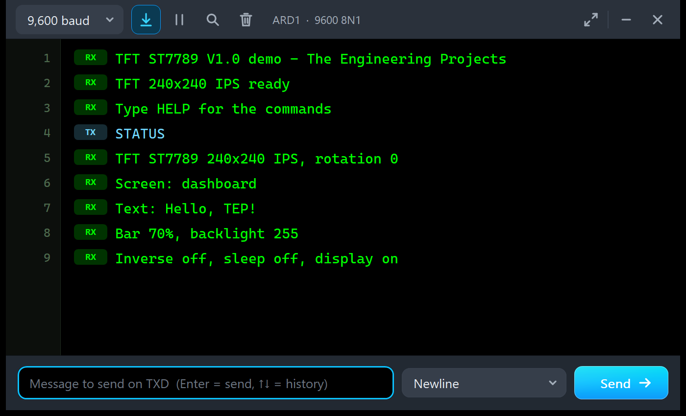
TFT ST7789 V1.0 demo - The Engineering Projects
TFT 240x240 IPS ready
Type HELP for the commands
STATUS
TFT ST7789 240x240 IPS, rotation 0
Screen: dashboard
Text: Hello, TEP!
Bar 70%, backlight 255
Inverse off, sleep off, display on
ARD2: FILL and TEST
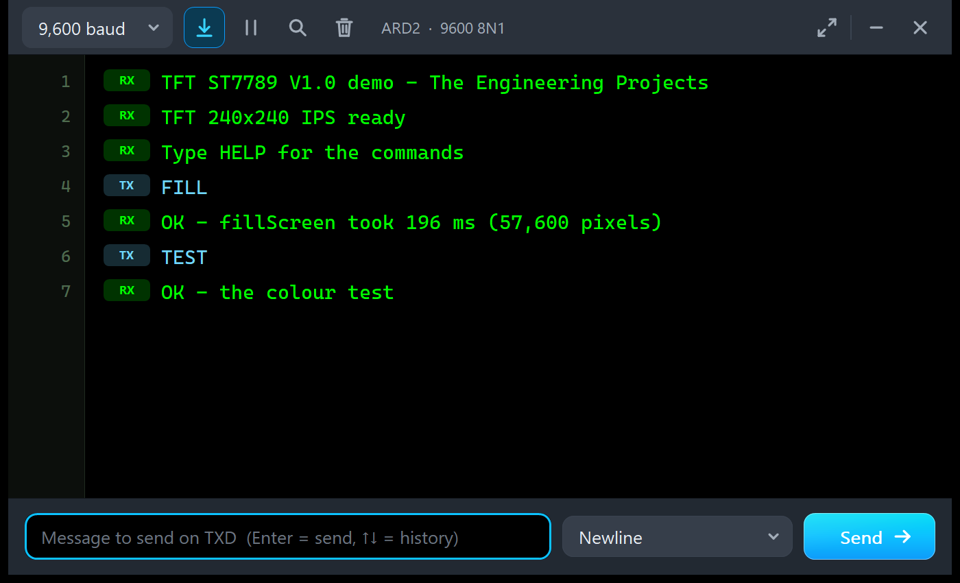
TFT ST7789 V1.0 demo - The Engineering Projects
TFT 240x240 IPS ready
Type HELP for the commands
FILL
OK - fillScreen took 196 ms (57,600 pixels)
TEST
OK - the colour test
The sketch measures 196 ms with millis() and the Speed tool 195.5 ms on the bus: the same fillScreen from both sides.
The Simulation Log
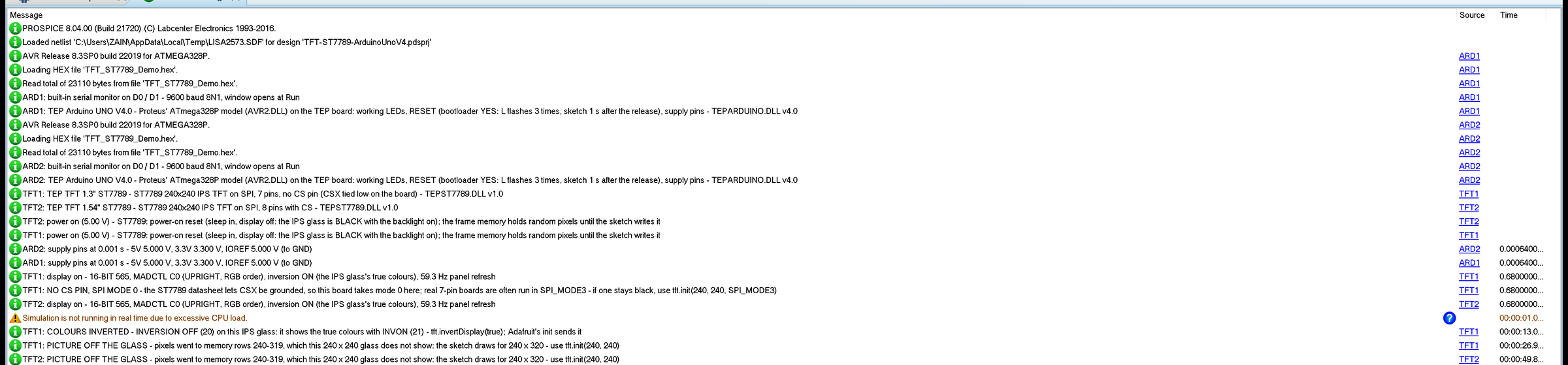
Every TFT writes a few lines to the simulation log: which board it is, the power-on reset, the first picture with its colour mode, rotation, inversion and the 59.3 Hz panel refresh, and one line for each classic mistake the first time it happens. Nothing repeats, so the log stays readable during a long run.
Troubleshooting
- A dark glass with the PWR LED off: no power - check VCC and GND.
- BLACK SCREEN - NOTHING ON SPI YET: check SCL on D13, SDA on D11, DC (and CS on the 1.54"), and that the sketch calls
tft.init(240, 240). - STILL IN SLEEP / DISPLAY OFF / STILL ASLEEP: the start-up is incomplete or too fast;
init()gets it right. - COLOURS INVERTED: the inversion is off - on IPS,
invertDisplay(true)means true colours. - PICTURE OFF THE GLASS: the sketch draws for 240 x 320; use
tft.init(240, 240). - RED / BLUE SWAPPED: MADCTL has the BGR bit set;
setRotation()sends RGB. - Rubbish on the 1.3" board after a glitch on SCL: without CS the bit count slipped; pulse RES.
- BACKLIGHT OFF: BLK is low; drive it high, PWM it or leave it open.
- No part or no monitor: TEPST7789.DLL or TEPARDUINO.DLL is missing from MODELS and the project folder; a closed monitor opens again with a click on the UNO's USB port.
Things to Know Before Using a Real ST7789 Module
- 3.3 V logic: the ST7789 is a 3.3 V chip. The boards have a regulator, so VCC 5 V is fine, but no level shifter: 1 kohm resistors in series with the signals, or a 74HC4050, are the safe way from a 5 V UNO.
- The SPI mode of 7-pin boards: if a real 1.3" board stays black, try
tft.init(240, 240, SPI_MODE3)on hardware SPI. - No CS, no sharing: the 1.3" board owns the SPI bus; use the 1.54" board next to an SD card.
- Always 240 x 240:
tft.init(240, 240)on both boards, whatever the example you copy says. - Memory: Adafruit_ST7789 keeps no picture in RAM; the demo needs 23,110 bytes of flash and 822 bytes of RAM.
Limitations of the Simulation
- Not modelled: reading from the ST7789 (drivers never need it), the partial mode's non-display area, the effect of gamma, power and VCOM settings, the response time, the tearing-effect output, any SPI-mode preference of a particular board (the model follows the datasheet), the current draw, and damage from 5 V signals.
- The LEDs, the strip and the panels are TEP additions.
- The model is our own, written from the ST7789 datasheet; ST7789 is a Sitronix part. This library is not made or endorsed by Sitronix, Adafruit or Labcenter.
- Licences: the Adafruit ST7735 and ST7789 library 1.11.0 (MIT licence), Adafruit GFX 1.12.6 (BSD licence), Adafruit BusIO 1.17.4 (MIT licence) and the Arduino AVR core 1.8.6 with LGPL-licensed code are in the HEX file; the README holds the licence texts.
- Tested in Proteus 8.5 in October 2026 (the demo as shipped on two Arduino UNO V4.0 boards with their built-in monitors: the dashboard on the 1.3" board without CS, the colour test on the 1.54" board, the Serial commands STATUS, LIGHT, INVERT, ROTATE, SLEEP / WAKE, SIZE 320 / 240 and FILL, the panel, the pop-up and the four tools; about 0.35 x real time with the pop-up and both monitors open). Proteus 7 is not supported.
Need another colour screen? Our TFT ST7735 Library for Proteus V1.0 has the classic 1.8" 128 x 160 module, our ILI9341 TFT LCD Library for Proteus V1.0 the 2.4" / 2.8" SPI module with touch, and our TFT LCD Shield Library for Proteus V1.0 the 2.4" UNO shield.
So, that was all about the ST7789 TFT LCD Library for Proteus V1.0. I hope the IPS glass, the 80-row offset and the board without CS hold no more surprises, so your 240 x 240 screen works the first time on the bench. If you use the ST7789 TFT LCD Library for Proteus in a project, please share it in the comments or in our forum, and if you have any questions, ask in the comments and I will help you out. Till the next tutorial, take care and have fun!