Hello friends, I hope you all are doing great. Today, I am going to share the new WS2812B NeoPixel Library for Proteus V1.0. WS2812B LEDs, better known as NeoPixels, are the addressable RGB LEDs on the round rings, the sticks and the 8x8 matrices that every maker has in a drawer. Each LED has its own little controller, so one Arduino pin sets the colour of every LED in a chain of hundreds. Clocks, lamps, mood lights, VU meters, signs and game displays all start with them. Now you can build and test them in Proteus.
Behind the parts sits our own model of the WS2812B, not a picture that changes colour. It reads the data on DIN bit by bit, by the HIGH time of every pulse, the way the real chip does: 24 bits a pixel in the order green, red, blue, the rest passed on to DOUT for the next board, and a LOW gap of 50 us that makes all the LEDs take their new colours at once. The timing really matters, so a sketch that is too slow fails here just like on your desk. You get ten devices: the rings of 12, 16 and 24 LEDs, the stick of 8 and the 8x8 matrix, each as a Simple device with a live STATUS panel and as an Advance device with a pop-up window and three test tools. The demo runs the Adafruit NeoPixel library on our Arduino UNO V4.0.
NOTICE: a NeoPixel library is easy to fake: read the colour from the sketch and paint the LED. We wanted more. Our LEDs read the real bits on DIN with their real timing, pass the rest of the frame on to the next board, keep their old colours when the sketch sends too few pixels, turn white when the bits are bit-banged and draw their real current from the 5V pin. It took our team a lot of hard work. Your feedback is the fuel that keeps us going, so please tell us what you think in the comments below or in the LCD Library board of our forum. And if our free libraries help you, you can buy us a coffee. So, let's get started with the WS2812B NeoPixel Library for Proteus V1.0:
What is a WS2812B (NeoPixel)?
A WS2812B is an RGB LED and its driver chip in one 5 x 5 mm package. Look at one closely and you see the small controller chip and three tiny LED dies, red, green and blue. The chip has a data input, DIN, and a data output, DOUT. You connect the DOUT of one LED to the DIN of the next, and so on, and the whole chain needs only one Arduino pin. NeoPixel is Adafruit's name for these LEDs and the boards made with them. The rings, sticks and matrices are simply WS2812B chains on a round, long or square board, with 5V, GND, DIN and DOUT pads.
| WS2812B (the model) | |
|---|---|
| Supply | 5 V on the 5V pin (the datasheet: 3.5 to 5.3 V) |
| Data | one wire, 800 kHz: a bit every 1.25 us, a 0 HIGH for about 0.4 us, a 1 HIGH for about 0.8 us |
| A pixel | 24 bits, most significant bit first, in the order GREEN, RED, BLUE (NEO_GRB in the sketch) |
| The chain | the first 24 x n bits of a frame are for this board's n LEDs; every later bit goes out on DOUT |
| The latch | DIN LOW for 50 us ends the frame (280 us for the newer WS2812B-V5): all LEDs show their new colours |
| Current | about 20 mA per colour at 255, so about 60 mA at full white, and about 1 mA for the chip |
| Boards in this library | rings of 12, 16 and 24 LEDs, a stick of 8, an 8x8 matrix of 64 LEDs |
| Devices | WS2812RING12TEP, WS2812RING16TEP, WS2812RING24TEP, WS2812STICK8TEP, WS2812MATRIX8TEP (Simple) and the same with ADVTEP (Advance) |
How the Data Works
There is no clock wire, so the time carries the information. Every bit starts with a rising edge on DIN. If the line goes LOW again after about 0.4 us, the bit is a 0; if it stays HIGH for about 0.8 us, the bit is a 1. The chip looks at the line at about 0.6 us after the rising edge, and that decides it. A bit lasts 1.25 us, which gives 800,000 bits a second, so the 24 bits of one pixel take only 30 us. The datasheet allows a 0 to be HIGH for 0.25 to 0.55 us and a 1 for 0.65 to 0.95 us.
These times are far too short for digitalWrite(). The Adafruit NeoPixel library therefore makes the bits in assembler, with the interrupts off, counting the clock cycles of the microcontroller. On a 16 MHz Arduino UNO a bit is 20 clock cycles: a 0 is HIGH for 5 cycles, 0.31 us, and a 1 for 13 cycles, 0.81 us. That is exactly what our model measured in Proteus: 0.312 us, 0.812 us and 1.250 us a bit.
The Chain and the Latch
The first LED of a chain keeps the first 24 bits it gets after a pause. Every bit after them, it sends out on DOUT, so the second LED sees the frame without the first pixel, keeps its 24 bits and passes the rest on, and so on down the chain. That is why the pixel numbers simply follow the wire: pixel 0 is the LED at DIN. When DIN stays LOW for longer than the latch time, 50 us for a WS2812B, every LED takes its new colour at the same moment. The Adafruit library waits 300 us between two frames, so it also works with the newer WS2812B-V5, which needs 280 us.
What's New in WS2812B NeoPixel Library for Proteus V1.0
- Five real boards: the rings of 12, 16 and 24 LEDs, the stick of 8 and the 8x8 matrix, black PCBs with the white 5 x 5 mm WS2812B packages seen from above: the lens, the controller chip and the red, green and blue dies.
- Two styles: each board as a Simple device with a STATUS panel and as an Advance device with a pop-up window.
- A real WS2812B model: every bit read by its HIGH time, 24 bits a pixel in GRB order, the latch by a LOW gap, and the later bits passed on to DOUT.
- Real chains: connect DOUT to the DIN of the next board, and the second board gets exactly the bits the first one did not keep.
- Live LEDs: each LED lights in its colour with a glow, and the pixels keep their colours between frames, like the real ones.
- A real current: each LED draws its current from the 5V pin, about 20 mA per colour at 255.
- Mistake detection: the wrong colour order, bits far too slow, bits outside the datasheet, a frame that stops inside a pixel, fewer or more pixels than the chain has, too much current for a USB port, VDD too low, data without power.
- Three test tools on the Advance devices: Timing, Chain and Power.
- A two-node demo on our Arduino UNO V4.0 with the Adafruit NeoPixel library: a ring of 16 on node 1, a stick of 8 and an 8x8 matrix in one chain of 72 pixels on node 2.
- A compact package: about 1.53 MB, without the C++ source code of the model.
Ten Devices: Three Rings, a Stick and an 8x8 Matrix
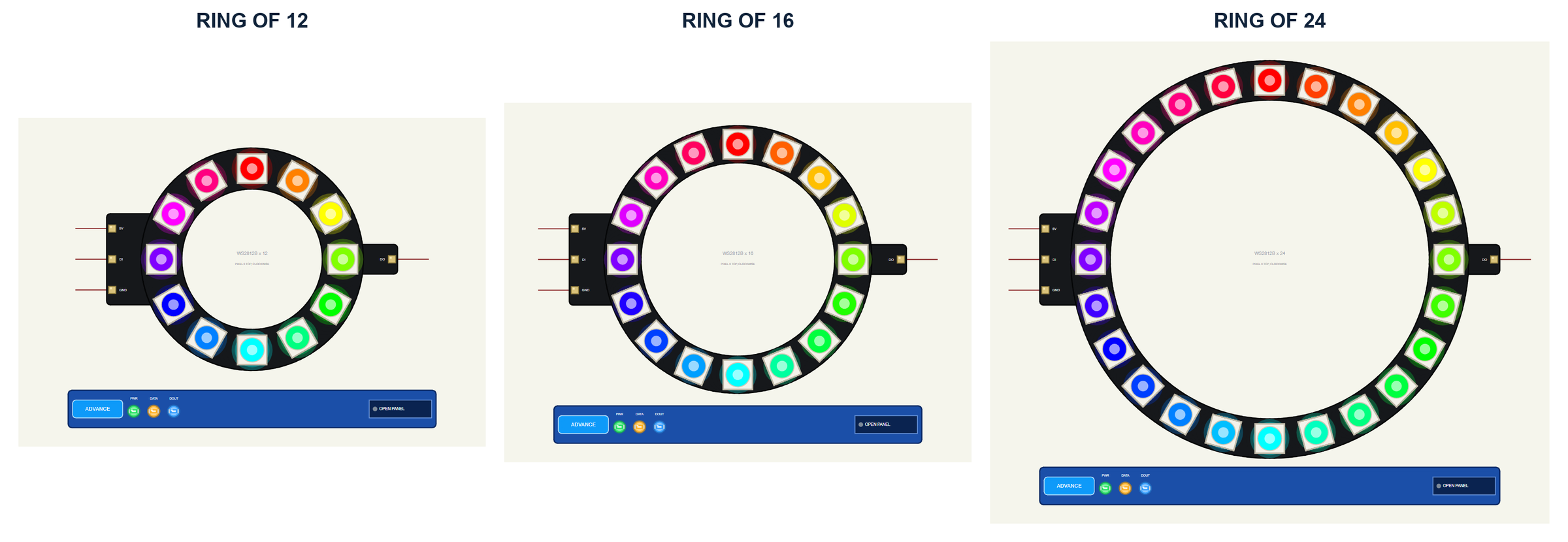
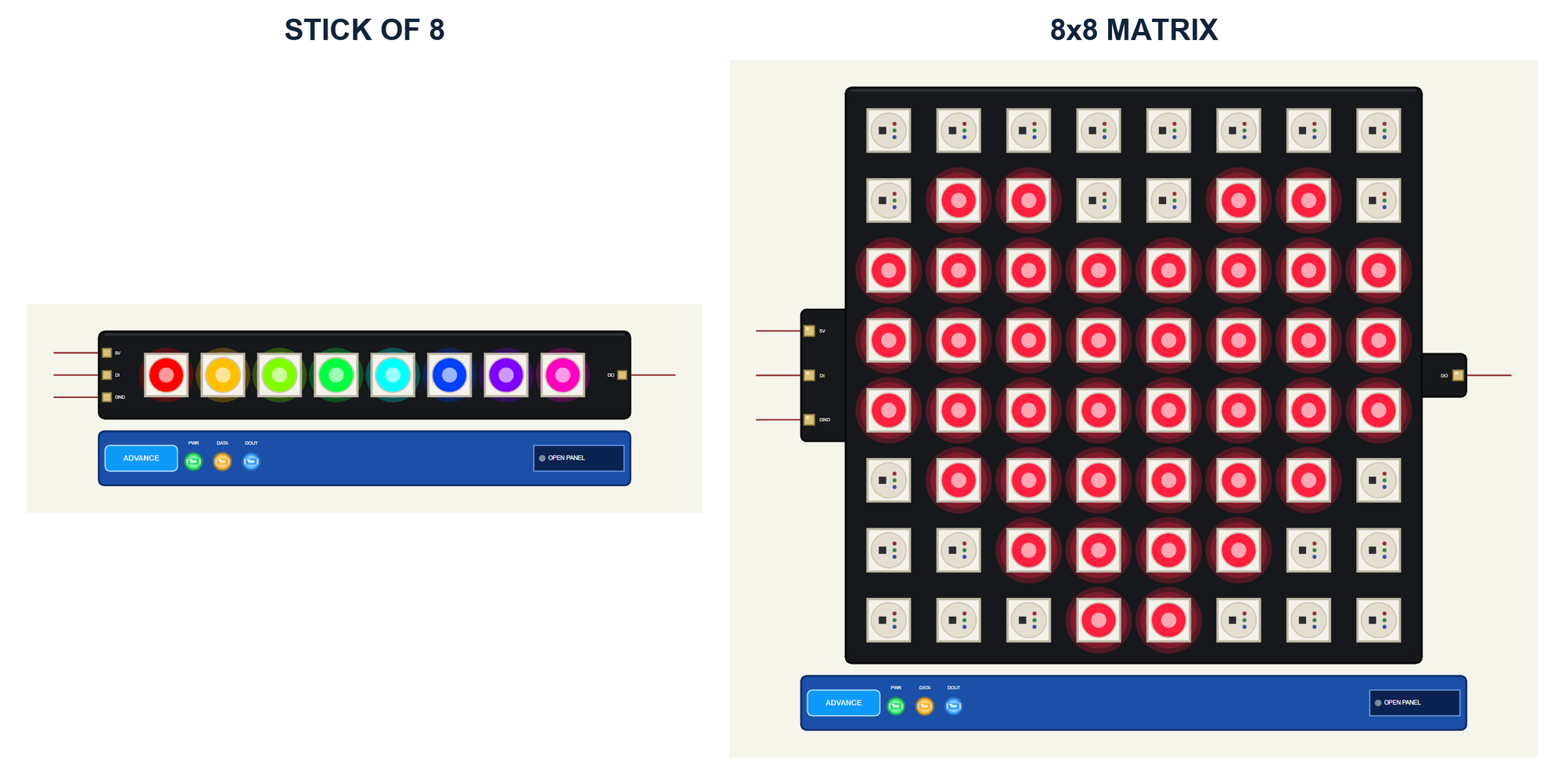
The boards look like the real ones. On the rings the LEDs sit around the board and face the centre, pixel 0 at the top and the numbers running clockwise. On the stick pixel 0 is at the DIN end. On the matrix pixel 0 is top left, and the rows run left to right, top to bottom. The real rings and the matrix carry their solder pads on the back; here they sit on two small tabs at the sides: 5V, DI and GND on the left, DO on the right. On the stick they sit at its two ends.
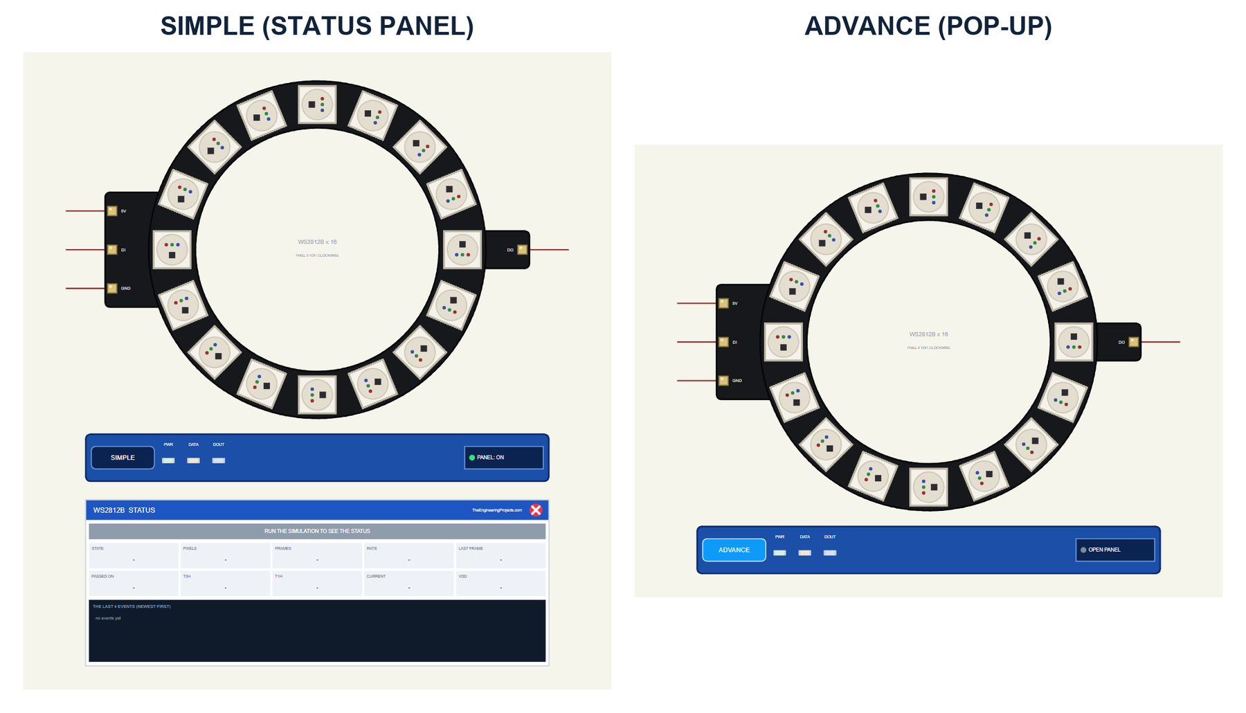
| Simple | Advance | |
|---|---|---|
| Devices | WS2812RING12TEP, WS2812RING16TEP, WS2812RING24TEP, WS2812STICK8TEP, WS2812MATRIX8TEP | WS2812RING12ADVTEP, WS2812RING16ADVTEP, WS2812RING24ADVTEP, WS2812STICK8ADVTEP, WS2812MATRIX8ADVTEP |
| On the schematic | The board, its strip and the STATUS panel | The board and its strip |
| Status | Banner, 10 readouts, the last 4 events | A pop-up: Board, Event log, Tests |
| Interaction | PANEL button on the strip | OPEN PANEL button on the strip |
Download WS2812B NeoPixel Library for Proteus
Click the button below to download WS2812B-NeoPixel-Library-for-Proteus-v1.0.zip (about 1.53 MB, without the C++ source code of the model):
WS2812B NeoPixel Library for Proteus V1.0: Ring, Stick, 8x8 Matrix- README.txt: the devices, installation, the demo, wiring, the test tools and real hardware.
- Proteus Library Files:
TEPWS2812.LIBandArduinoV4TEP.LIBfrom our Arduino Library for Proteus V4.0. - Proteus Model Files:
TEPWS2812.DLLandTEPARDUINO.DLL. - Proteus Simulation:
WS2812B-NeoPixel-ArduinoUnoV4.pdsprj,NeoPixel_Demo.hexand copies of the two DLLs. - Arduino Code:
NeoPixel_Demo.ino. It needs the Adafruit NeoPixel library from the Library Manager of the Arduino IDE, only if you want to change the sketch.
No Proteus yet? Read How to Download and Install Proteus 7 and 8. New to libraries? Follow How to Install a New Library in Proteus.
How to Install WS2812B NeoPixel Library for Proteus
- Close Proteus and extract the whole zip file, for example to your Desktop.
- Copy the two files from Proteus Library Files into the LIBRARY folder of Proteus (usually
C:\Program Files (x86)\Labcenter Electronics\Proteus 8 Professional\LIBRARY). - Copy
TEPWS2812.DLLandTEPARDUINO.DLLfrom Proteus Model Files into the MODELS folder. - Delete
TEPWS2812.IDXfrom the LIBRARY folder if it is there. - Start Proteus, press P and search for WS2812.
Tip: keep the Proteus Simulation folder together, because the project needs its .hex file and the DLLs beside it. The library is tested in Proteus 8.5; Proteus 7 is not supported. For a single-colour 8x8 LED matrix, see our MAX7219 LED Matrix library.
The WS2812B Boards in Proteus
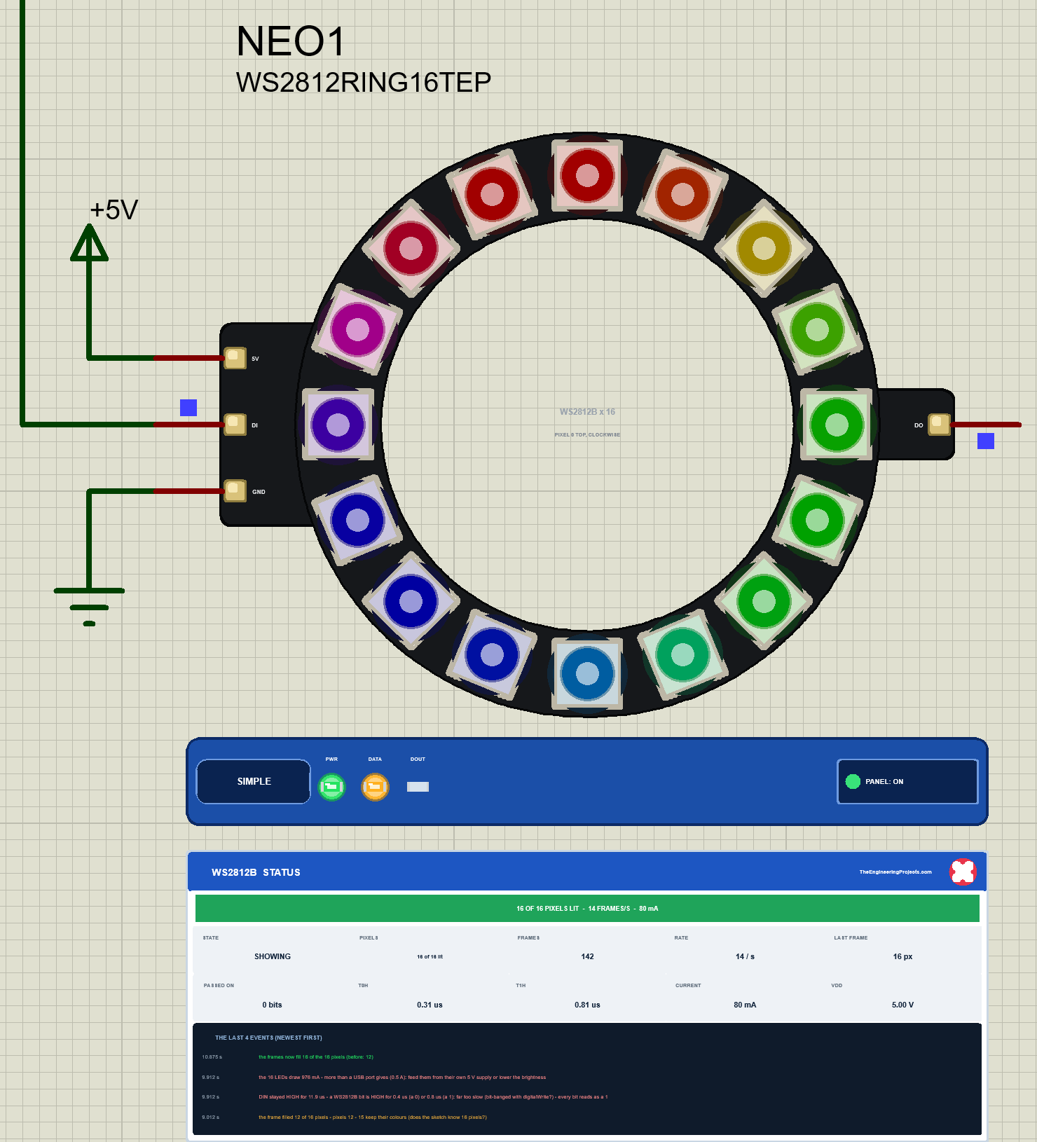
While the simulation runs, every LED lights in the colour of its last frame, with a soft glow around it. A dark LED shows the white package with its chip and its three dies. Under the board is the TEP strip with the SIMPLE or ADVANCE badge and three LEDs: PWR lights while the board has its 5 V, DATA while frames come in on DIN, and DOUT while the board passes bits on to the next one. The tabs, the strip, its LEDs and the panels are TEP additions; the real boards have none of them.
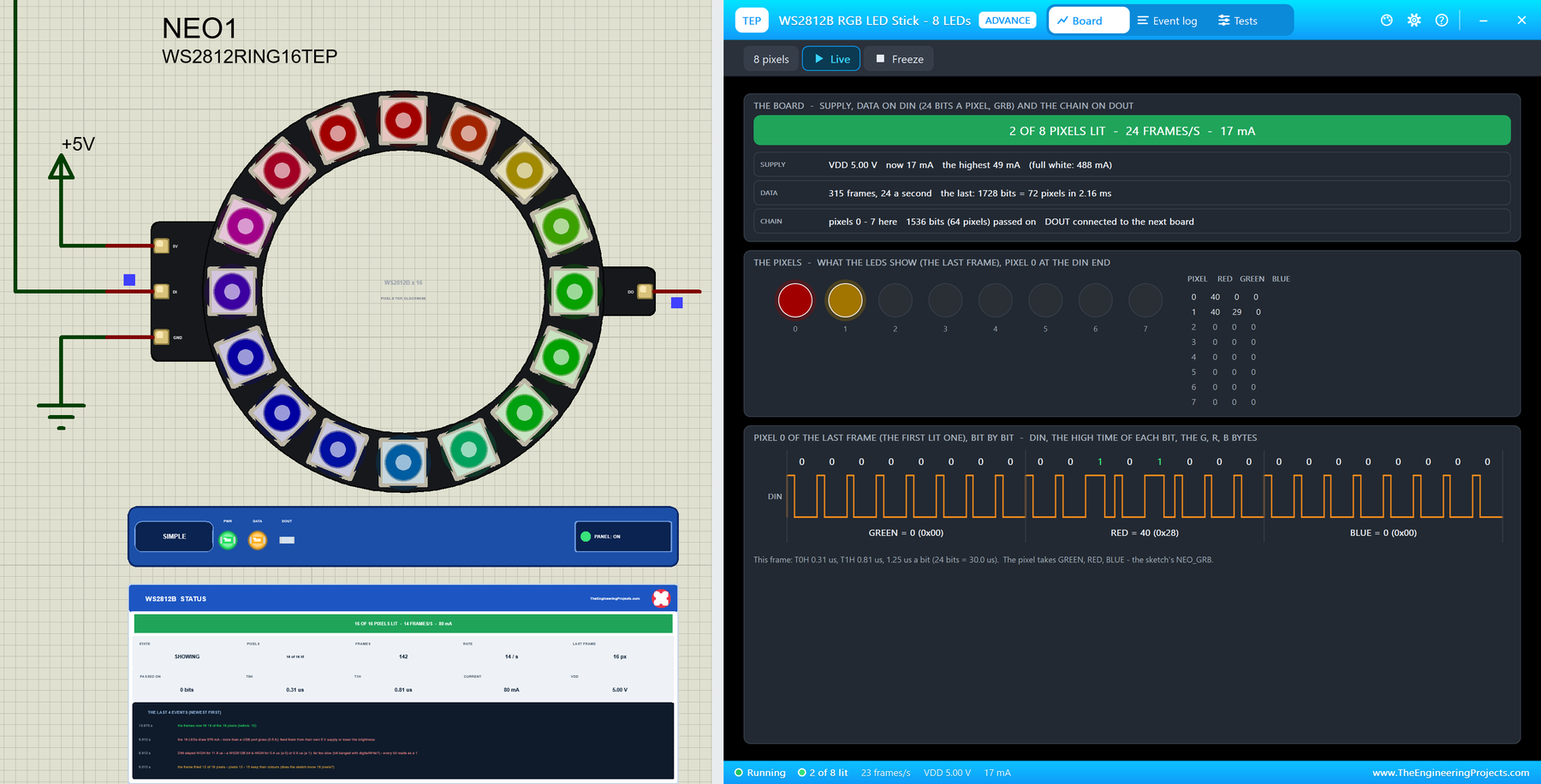
The Simple device adds the STATUS panel. Its banner sums up the board, here "16 OF 16 PIXELS LIT - 14 FRAMES/S - 80 mA"; before the first frame it says WAITING FOR DATA ON DIN, and it turns red with the latest warning. Ten readouts follow: the state (SHOWING while frames come in, HOLDING when the sketch stops sending), the pixels lit, the frames so far and their rate, the pixels of the last frame, the bits passed on to DOUT, the HIGH times of the 0s and the 1s (T0H 0.31 us and T1H 0.81 us), the current and VDD. At the bottom are the last four events. In this picture they are still the notes of the mistakes we made before, which you will meet below. The red X closes the panel, and the PANEL button on the strip opens it again.
The Advance device keeps the schematic clean: only the board and its strip. Its live data opens in a pop-up window at Run, and the OPEN PANEL button brings the window back if you close it. Two properties are worth knowing: LATCH, the latch time in microseconds (50 for a WS2812B, 280 for a WS2812B-V5), and on the Simple devices PANEL, the STATUS panel open or closed at the start.
The Demo Circuit
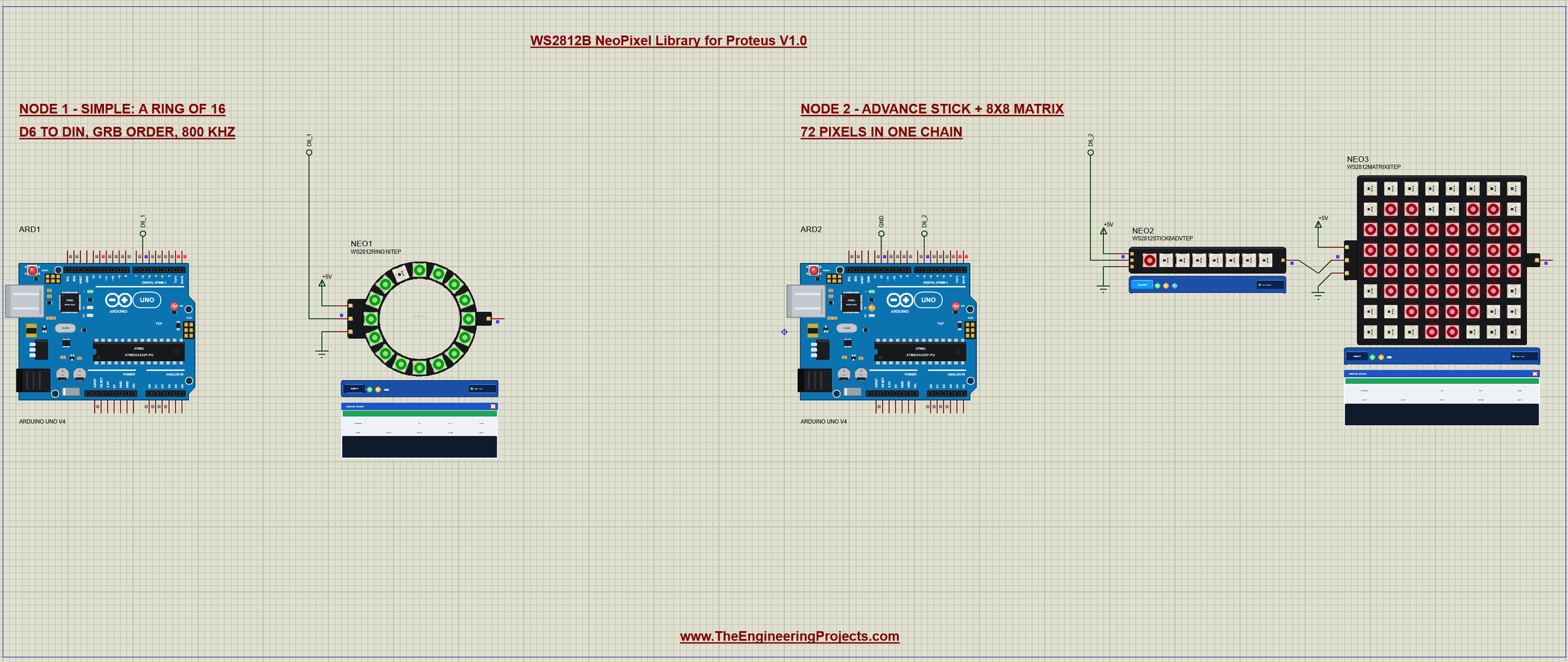
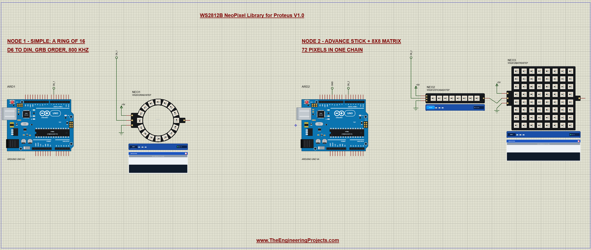
The demo project has two nodes. Each one is an Arduino UNO V4.0 from our Arduino UNO Library for Proteus V4.0, and both run the same NeoPixel_Demo.hex. Node 1 drives a ring of 16 LEDs (Simple). Node 2 drives a stick of 8 (Advance), and the DOUT of the stick goes to the DIN of an 8x8 matrix (Simple): one chain of 72 pixels on one Arduino pin. Node 2's D12 is connected to GND, which tells the sketch about the longer chain.
Wiring
| WS2812B board | Arduino UNO | Note |
|---|---|---|
| DIN | D6 | any digital pin; on a real board through a 300 to 500 ohm resistor |
| 5V | a 5 V supply | the UNO's 5V only for a few LEDs at low brightness |
| GND | GND | common with the Arduino |
| DOUT | DIN of the next board | or open on the last board |
In Proteus every DIN reaches its UNO through a wire with a net label, D6_1 for node 1 and D6_2 for node 2, and each board gets its 5V from a +5V terminal and its GND from a ground terminal, because LEDs want their own 5 V supply. The only direct wire between two boards is the one from the stick's DO to the matrix's DI. The serial monitor needs no wires at all, because it is built into the UNO V4.0.
Node 1: the Ring of 16
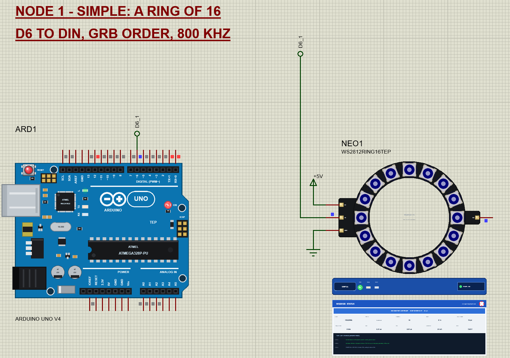
Node 1 is the classic first NeoPixel project: one ring, three wires. The tour shows a colour wipe in red, green and blue, one pixel after the other, then a theatre chase of every third pixel, then a rainbow that turns around the ring, a short dark pause, and the tour starts again.
Node 2: a Stick of 8 and an 8x8 Matrix in One Chain
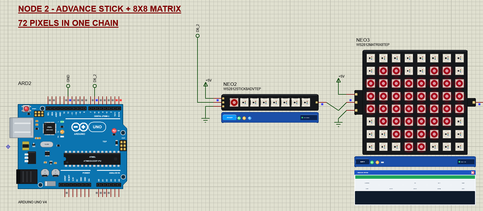
Node 2 runs the same tour over all 72 pixels: pixels 0 to 7 are the stick and pixels 8 to 71 the matrix. After the rainbow it adds the PICTURES: a heart and a smiley on the matrix, while the stick shows a little level bar. The heart lights 40 of the 64 LEDs of the matrix and draws 208 mA at the demo's brightness of 40.
The Arduino Code
The demo sketch uses the Adafruit NeoPixel library (version 1.12.3), the most common way to drive these LEDs. New to Arduino? Start with Arduino Tutorial for Beginners and Introduction to Arduino UNO. The sketch begins with its pins and one strip object for the whole chain:
const uint8_t DATA_PIN = 6;                    // the first board's DIN
const uint8_t SELECT_PIN = 12;                 // open = node 1 (a ring of 16), to GND = node 2 (a stick of 8 + an 8x8 matrix)
const uint8_t BRIGHTNESS = 40;                 // of 255: 16 LEDs at full white take about 1 A at 255, about 0.16 A at 40
uint16_t PIXELS = 16;                          // every pixel of the chain
bool matrix = false;                           // node 2: pixels 8 - 71 are the 8x8 matrix

Adafruit_NeoPixel strip(72, DATA_PIN, NEO_GRB + NEO_KHZ800);
The strip is made for the longest chain, 72 pixels. In setup() the sketch reads D12 and sets the real length: 16 for the ring, 72 for the stick and the matrix. begin() makes D6 an output, and the first show() sends a frame with every pixel dark:
  strip.updateLength(PIXELS);
  strip.begin();                                // DIN as an output, LOW
  strip.setBrightness(BRIGHTNESS);
  strip.show();                                 // every pixel dark
The colour wipe shows the basic rhythm of every NeoPixel sketch: set the colours in RAM with setPixelColor(), then send them all with show(). Nothing changes on the LEDs until show():
  if (stage == 0) {                             // colour wipe: one more pixel each frame
    static const uint32_t C[3] = {0xFF0000, 0x00FF00, 0x0000FF};
    if (step == 0) strip.clear();
    strip.setPixelColor(step, C[colour]);
    strip.show();
    nextAt = now + (matrix ? 15 : 40);
    if (++step >= PIXELS) { step = 0; if (++colour == 3) startStage(1); }
On node 2 the matrix starts at pixel 8, right after the stick, so a picture is just an offset and a row number. Each row of the heart is one byte in flash:
void picture(const uint8_t* rows, uint32_t c) {  // an 8x8 picture on the matrix (pixel 8 = top left, rows left to right)
  for (uint8_t r = 0; r < 8; ++r) {
    const uint8_t bits = pgm_read_byte(rows + r);
    for (uint8_t col = 0; col < 8; ++col) strip.setPixelColor(8 + r * 8 + col, bits & (0x80 >> col) ? c : 0);
  }
}
The commands make the classic mistakes on purpose. COUNT n changes the pixel count of the strip, so the sketch sends fewer or more pixels than the boards have:
  else if (!strcmp(s, "COUNT") && v[0] > 0) {                     // the sketch's pixel count does not match the chain
    strip.updateLength(constrain(v[0], 1, 80)); strip.setBrightness(BRIGHTNESS);
    strip.fill(strip.Color(0, 0, 255)); strip.show();
RGB switches the strip to NEO_RGB, the wrong colour order for a WS2812B, and fills it with red, green, blue, red, green, blue; GRB puts it right:
  } else if (!strcmp(s, "RGB") || !strcmp(s, "GRB")) {             // the colour order: a WS2812B takes G, R, B
    strip.updateType((s[0] == 'R' ? NEO_RGB : NEO_GRB) + NEO_KHZ800);
    strip.clear();
    for (uint16_t k = 0; k + 2 < strip.numPixels(); k += 3) { strip.setPixelColor(k, 255, 0, 0); strip.setPixelColor(k + 1, 0, 255, 0); strip.setPixelColor(k + 2, 0, 0, 255); }
    strip.show();
WHITE sets every pixel to full white at full brightness, to show the current:
  } else if (!strcmp(s, "WHITE")) {                               // full white at full brightness: the current
    strip.setBrightness(255); strip.fill(strip.Color(255, 255, 255)); strip.show();
And SLOW makes the bits the way a beginner might try first, with digitalWrite(). Each call takes about 4 us on an UNO, many times the 0.4 us a 0 should last:
// the classic mistake: the bits bit-banged with digitalWrite() - each call takes about 4 us, a WS2812B wants 0.4 / 0.8 us
void slowShow() {
  const uint8_t* p = strip.getPixels();
  for (uint16_t i = 0; i < strip.numPixels() * 3; ++i)
    for (uint8_t m = 0x80; m; m >>= 1) {
      digitalWrite(DATA_PIN, HIGH);
      if (!(p[i] & m)) digitalWrite(DATA_PIN, LOW);   // a 0: LOW "at once" - still about 4 us later
      digitalWrite(DATA_PIN, LOW);
    }
  delayMicroseconds(300);
}
The HEX file is in the package, so you do not need the Arduino IDE to run the demo. To change the sketch, install "Adafruit NeoPixel" from the Library Manager, open the sketch in the Arduino IDE and export the compiled binary, as in How to get the HEX file from Arduino. It needs 10,914 bytes of flash and 383 bytes of RAM, plus 3 bytes a pixel at run time (216 bytes for 72 pixels).
The Serial Monitor
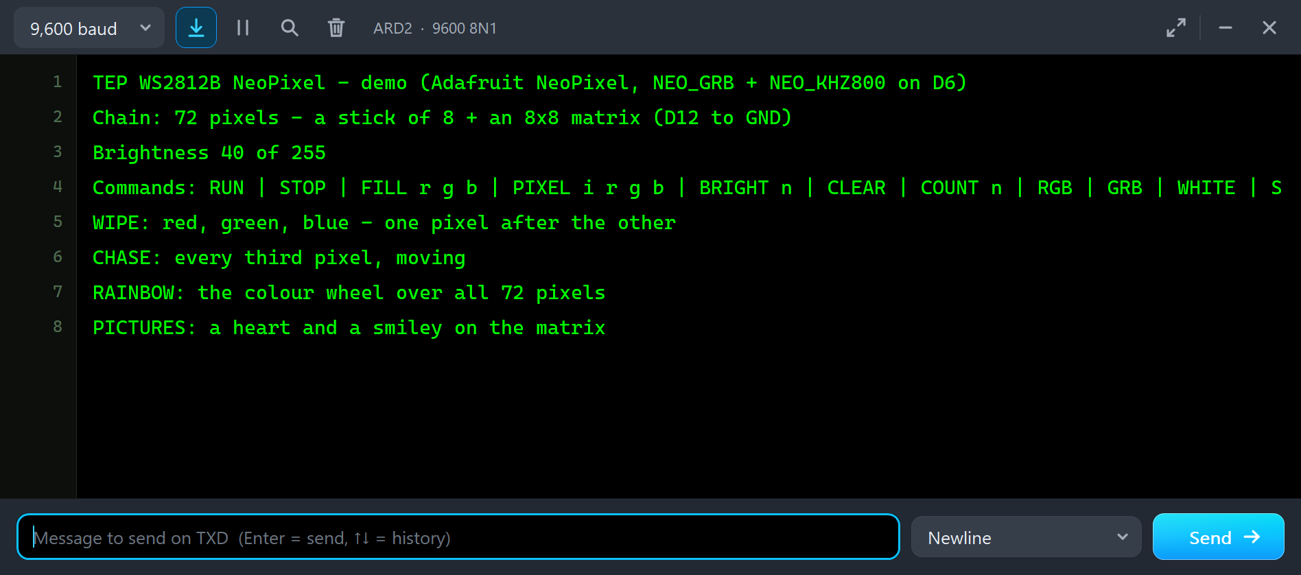
Both UNOs have the serial monitor built in, and it opens at Run. The screenshots use its Simple interface. Node 2 starts like this; after the third line comes the list of commands, which is wider than the window:
TEP WS2812B NeoPixel - demo (Adafruit NeoPixel, NEO_GRB + NEO_KHZ800 on D6)
Chain: 72 pixels - a stick of 8 + an 8x8 matrix (D12 to GND)
Brightness 40 of 255
WIPE: red, green, blue - one pixel after the other
CHASE: every third pixel, moving
RAINBOW: the colour wheel over all 72 pixels
PICTURES: a heart and a smiley on the matrix
Node 1 reports a chain of 16 pixels with D12 open, and its tour has no pictures.
Commands
Type a command in the monitor and press Enter. STOP stops the tour and the LEDs keep their colours, FILL 0 0 255 makes every pixel blue, PIXEL 3 255 0 0 makes pixel 3 red, BRIGHT 80 changes the brightness, CLEAR turns every pixel off, STATUS prints the pixel count and the brightness, RUN starts the tour again and HELP lists them all. COUNT n, RGB, GRB, WHITE and SLOW make the mistakes below. The commands are not case-sensitive.
The Advance Pop-Up Window
At Run, the Advance device opens a window named after its board, here WS2812B RGB LED Stick - 8 LEDs, with the look of our TEP Serial Monitor Advance for Proteus. It has three tabs, Board, Event log and Tests, plus Settings and Help behind the gear and question mark icons. The status bar at the bottom always shows the pixels lit, the frame rate, VDD and the current.
The Board Page
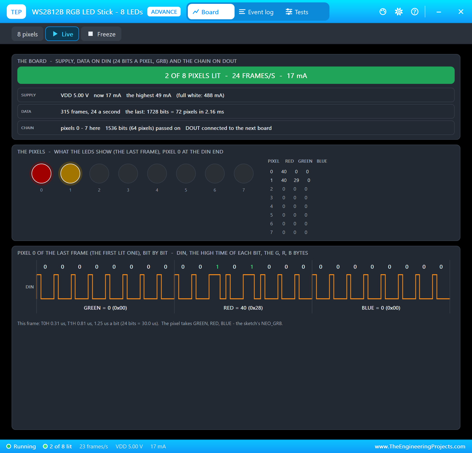
The top card is the board. The banner sums it up, here "2 OF 8 PIXELS LIT - 24 FRAMES/S - 17 mA". Under it, SUPPLY shows VDD, the current now, the highest current so far and the current at full white (488 mA for the 8 LEDs). DATA counts the frames and their rate and tells what the last frame was: 1728 bits = 72 pixels in 2.16 ms. CHAIN shows that the stick kept pixels 0 to 7 and passed 1536 bits, 64 pixels, on to DOUT, which is connected to the next board.
The middle card shows the pixels as the LEDs show them, in the board's own shape, with their red, green and blue values. The level bar has lit two of them: pixel 0 red (40, 0, 0) and pixel 1 orange (40, 29, 0). Those small numbers are the demo's brightness of 40 at work.
The bottom card is the best part: the first lit pixel of the last frame, bit by bit. You see DIN with its 24 pulses, each labelled 0 or 1, and the three bytes they make: GREEN = 0, RED = 40 (0x28), BLUE = 0. The green byte comes first, because a WS2812B wants GRB. The narrow pulses are the 0s, the two wider ones in the red byte are the 1s of 0x28. The line under it measures this frame: T0H 0.31 us, T1H 0.81 us, 1.25 us a bit, 30.0 us for the 24 bits. Freeze holds the page for a closer look.
The Event Log
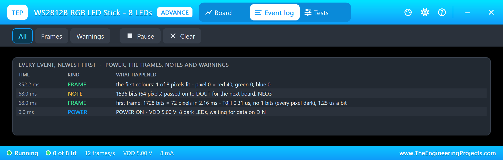
The Event log lists everything that happened, newest first, with its time and kind. At 0.0 ms the board gets its power: "8 dark LEDs, waiting for data on DIN". At 68.0 ms the first frame arrives, the one from setup(): 1728 bits, "no 1 bits (every pixel dark)". The note in the same instant names the next board in the chain: "1536 bits (64 pixels) passed on to DOUT for the next board, NEO3". The model finds that name by itself, from the wire on DOUT. Then the wipe starts: "the first colours: 1 of 8 pixels lit - pixel 0 = red 40, green 0, blue 0". Filter the log by frames or warnings, pause it, or clear it.
The Test Tools
The Tests tab holds three tools, each with a "Good for:" line and a green, amber or red verdict per row. Timing checks the bits on DIN against the datasheet, Chain the pixel count, and Power VDD and the current. We will use all three on the mistakes below.
Classic WS2812B Mistakes, Simulated
The demo sketch can make the most common NeoPixel mistakes on purpose, so you can see what they look like before they happen on your desk. All of them were run in the final test, on the ring of node 1 and on the chain of node 2. This is node 1's monitor:
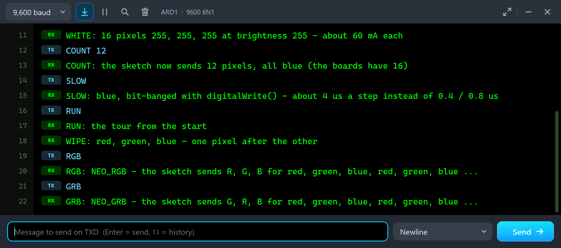
WHITE: 16 pixels 255, 255, 255 at brightness 255 - about 60 mA each
COUNT 12
COUNT: the sketch now sends 12 pixels, all blue (the boards have 16)
SLOW
SLOW: blue, bit-banged with digitalWrite() - about 4 us a step instead of 0.4 / 0.8 us
RUN
RUN: the tour from the start
WIPE: red, green, blue - one pixel after the other
RGB
RGB: NEO_RGB - the sketch sends R, G, B for red, green, blue, red, green, blue ...
GRB
GRB: NEO_GRB - the sketch sends G, R, B for red, green, blue, red, green, blue ...
The Wrong Colour Order: RGB Instead of GRB
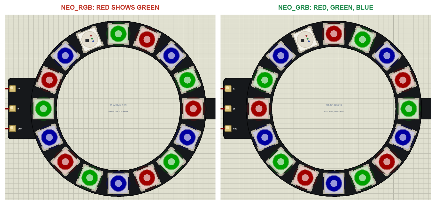
This is the most common NeoPixel question of all: "I set red, why is it green?" A WS2812B takes its bytes in the order green, red, blue. With NEO_RGB the library sends red first, the LED takes it as green, and red and green swap. Blue is the third byte in both orders, so it stays blue, which makes the mistake even more confusing. Use NEO_GRB for WS2812B LEDs; a few other LED types really are RGB, which is why the library offers both.
Too Much Current: Full White
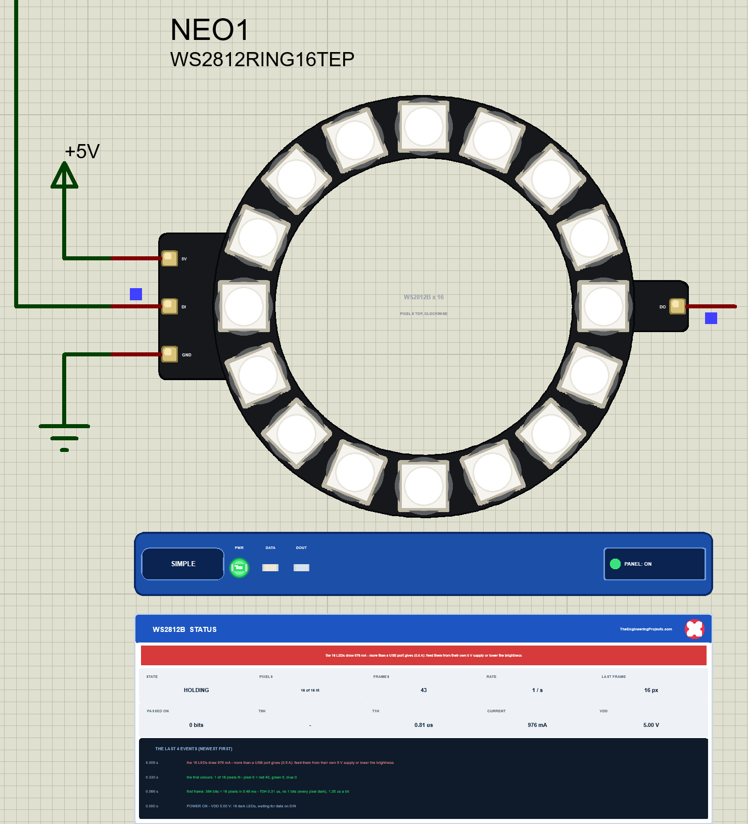
WHITE sets all 16 LEDs to full white at full brightness. Each one now draws about 61 mA, 60 mA for its three colours and about 1 mA for its chip, so the ring takes 976 mA from its 5V pin. The banner turns red: "the 16 LEDs draw 976 mA - more than a USB port gives (0.5 A): feed them from their own 5 V supply or lower the brightness". On a real Arduino powered from USB, this is the moment it resets or the LEDs turn yellow.
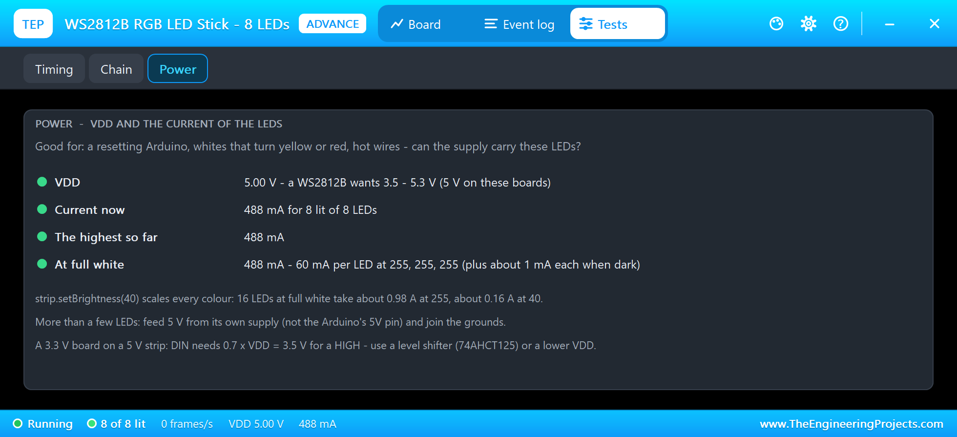
The Power tool of the stick shows the same on node 2: VDD 5.00 V against the 3.5 to 5.3 V of the datasheet, 488 mA for its 8 LEDs, the highest so far and the value at full white. The stick alone stays under 0.5 A, so its rows are green. The matrix behind it is a different story: its 64 LEDs draw 3.90 A, and its log says so. The tool also reminds you that setBrightness(40) takes a ring of 16 from about 0.98 A down to about 0.16 A.
Fewer Pixels Than the Board Has
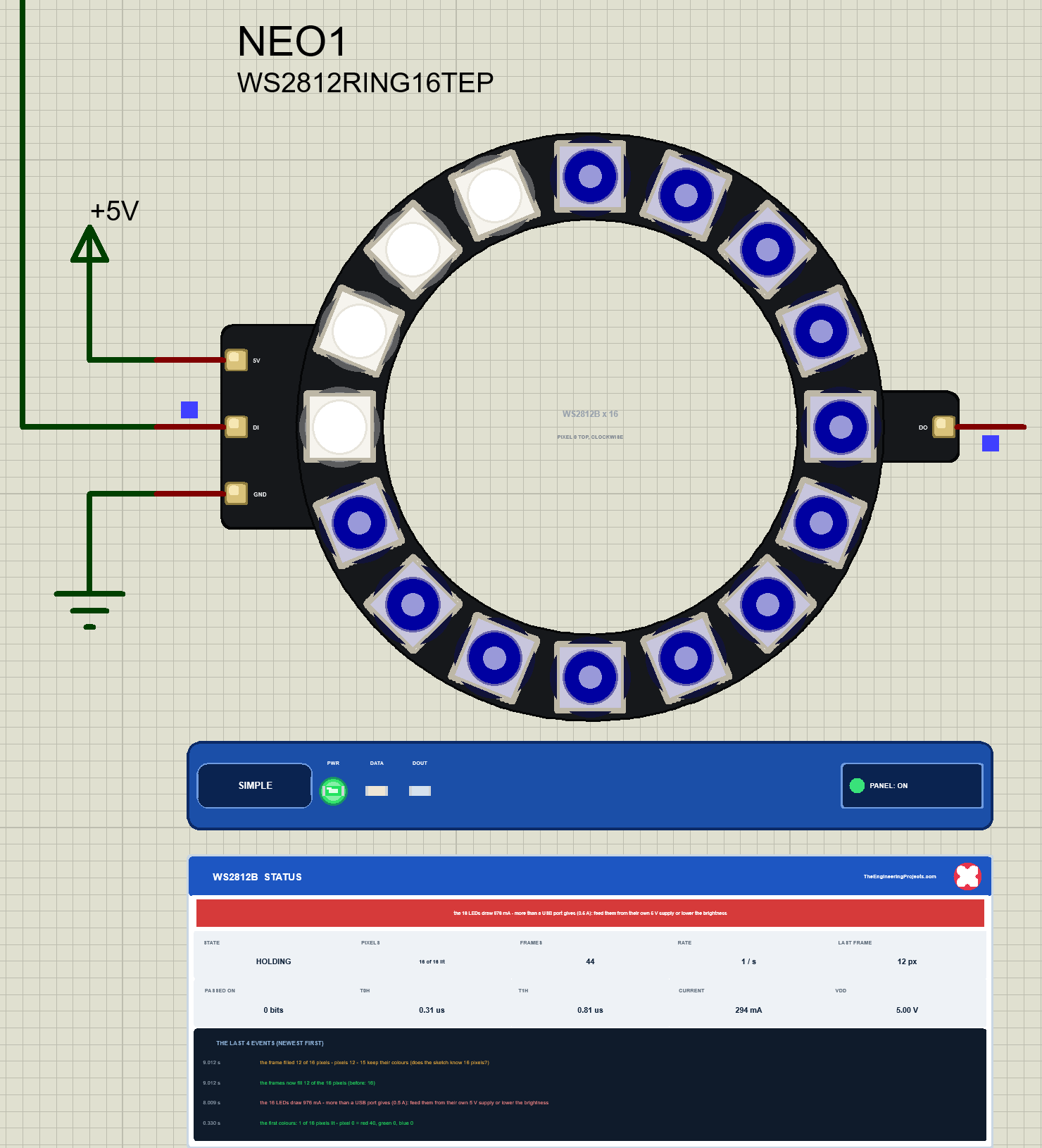
COUNT 12 tells the strip that it has 12 pixels, so show() sends only 288 bits. Pixels 0 to 11 turn blue. Pixels 12 to 15 get no bits at all, and a WS2812B that gets no bits keeps its colour: they stay white from the frame before. The panel shows LAST FRAME 12 px, and the events say "the frames now fill 12 of the 16 pixels (before: 16)" and "the frame filled 12 of 16 pixels - pixels 12 - 15 keep their colours (does the sketch know 16 pixels?)". On a real board this looks like broken LEDs at the end. It is only a wrong number in the sketch.
The Chain: Too Few and Too Many Pixels
Node 2 shows the same mistake in a chain, where it is harder to spot. Its monitor:
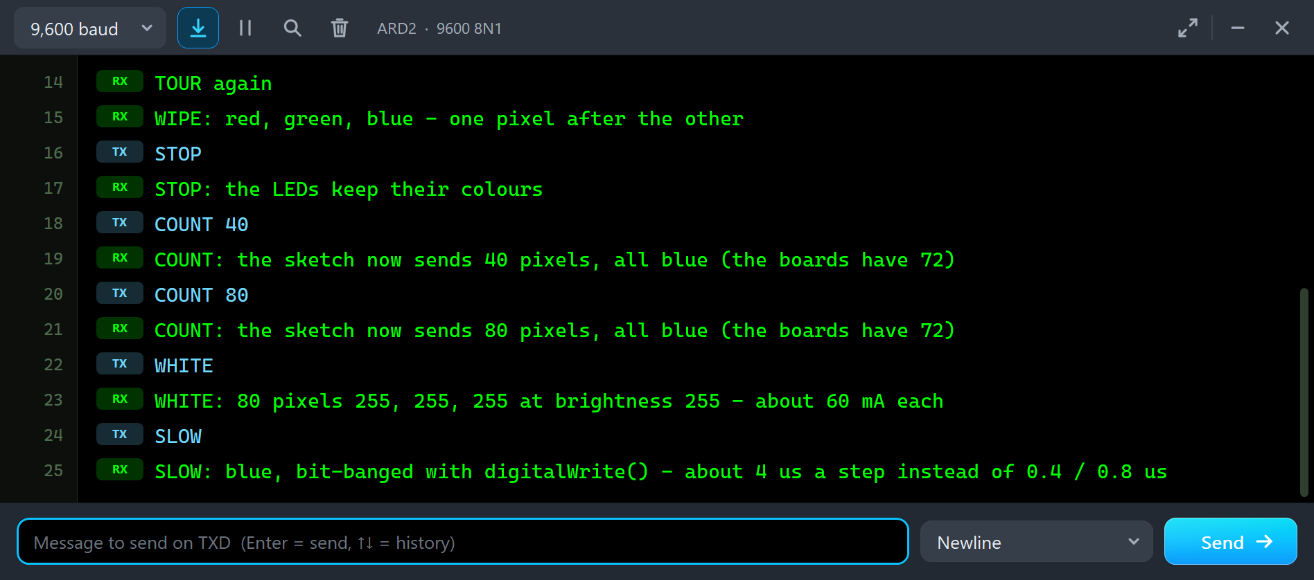
TOUR again
WIPE: red, green, blue - one pixel after the other
STOP
STOP: the LEDs keep their colours
COUNT 40
COUNT: the sketch now sends 40 pixels, all blue (the boards have 72)
COUNT 80
COUNT: the sketch now sends 80 pixels, all blue (the boards have 72)
WHITE
WHITE: 80 pixels 255, 255, 255 at brightness 255 - about 60 mA each
SLOW
SLOW: blue, bit-banged with digitalWrite() - about 4 us a step instead of 0.4 / 0.8 us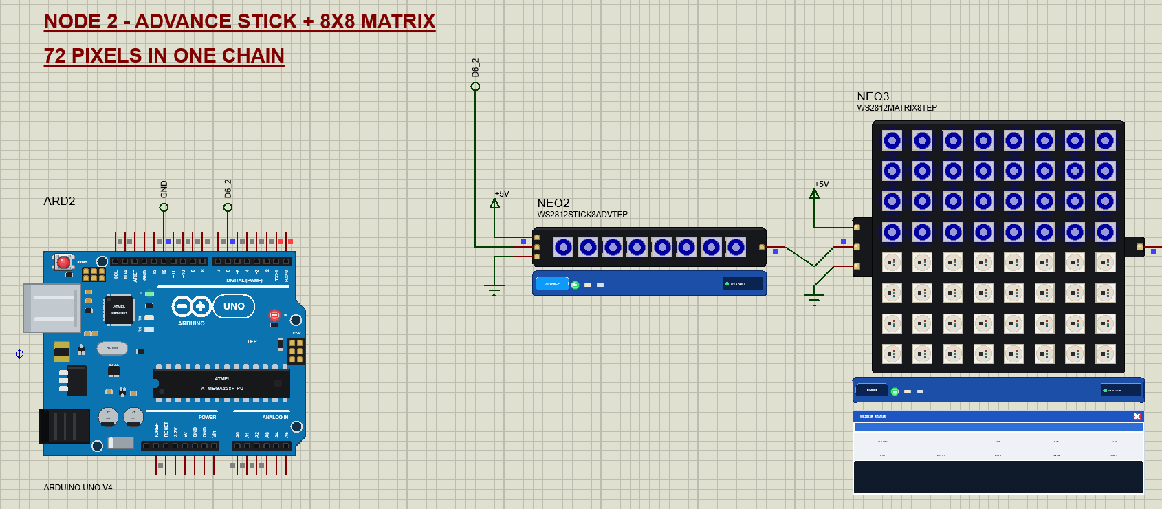
With COUNT 40 the sketch sends 40 pixels into a chain of 72. The stick keeps its 8 and passes 32 on, so the matrix fills its upper four rows. Its lower half keeps what it showed before, which is dark here, because the STOP came at the start of a wipe. The stick itself has no problem, and its Chain tool says so:
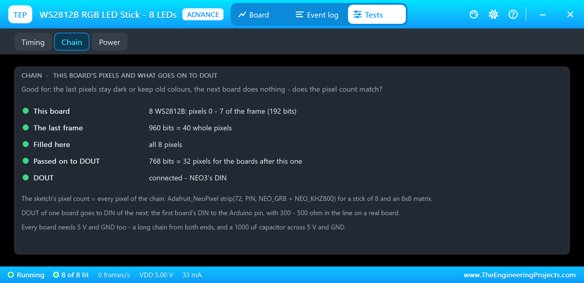
The Chain tool shows this board's pixels (0 to 7 of the frame, 192 bits), the last frame (960 bits = 40 whole pixels), how many filled here (all 8), the bits passed on to DOUT (768 bits = 32 pixels for the boards after this one), and whether DOUT is connected: "connected - NEO3's DIN". Every row is green, because for the stick everything is fine. The note about the missing pixels comes from the matrix. Then COUNT 80 sends 80 pixels into the same chain:
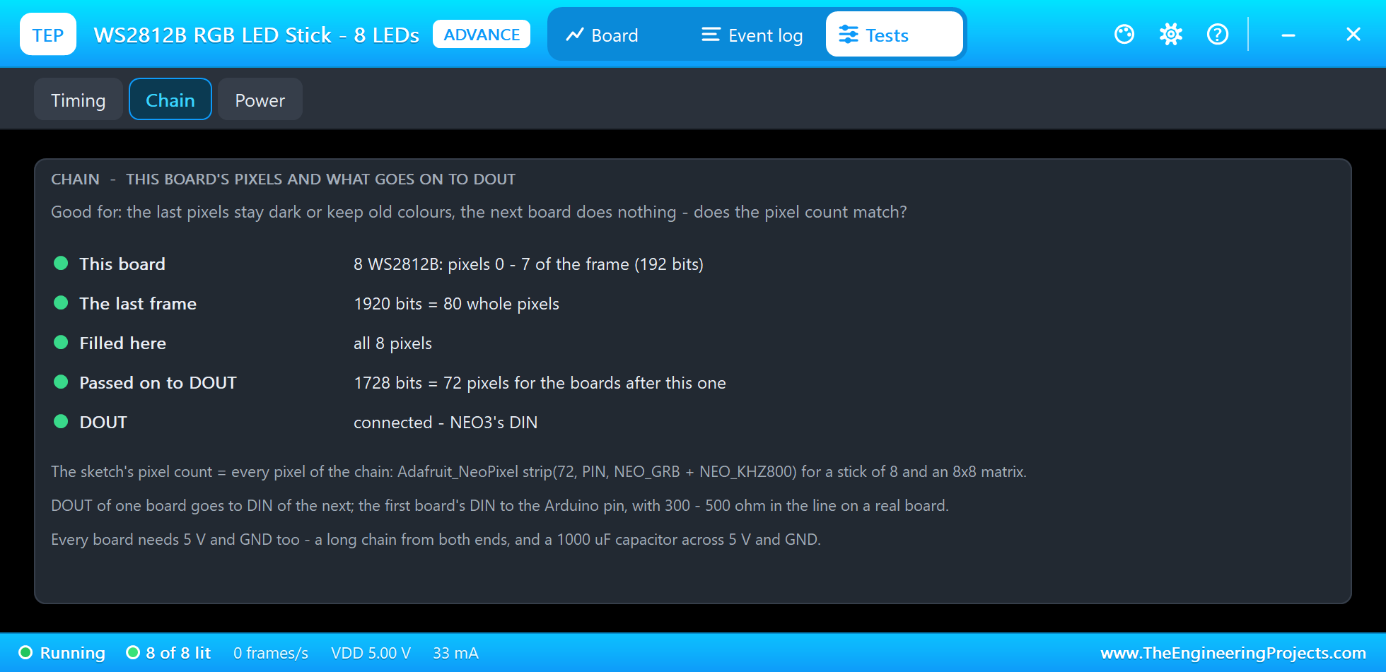
Now the stick passes 1728 bits on, 72 pixels for a matrix of 64. The matrix keeps its 64 and has 192 bits left over. It would pass them on, but nothing is on its DOUT. The simulation log of the run tells both stories:
NEO3: the frames now fill 32 of the 64 pixels (before: 64) at 26.4131 s
NEO3: the frame filled 32 of 64 pixels - pixels 32 - 63 keep their colours (does the sketch know 64 pixels?) at 26.4131 s
NEO3: the frame has 192 bits (8 pixels) more than these 64 LEDs, but no WS2812B board is on DOUT - the sketch sends more
      pixels than the chain has at 28.7147 s
NEO3: the 64 LEDs draw 3.90 A - more than a USB port gives (0.5 A): feed them from their own 5 V supply or lower the
      brightness at 30.9125 s
Too many pixels does no harm on a real chain; the extra bits fall off the end. But the sketch and the hardware do not agree, often because a board is missing or its DOUT is not connected. The last line is the WHITE on node 2.
Bits Far Too Slow: digitalWrite()
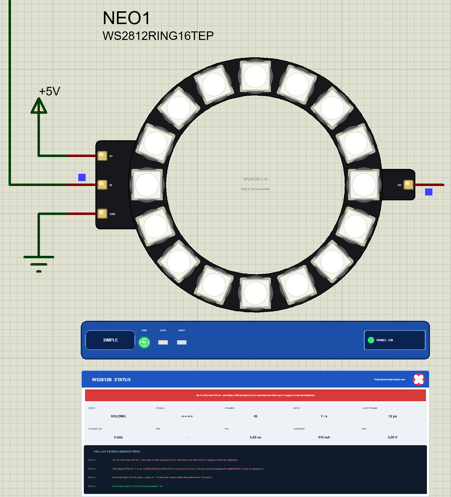
SLOW asks for blue, but it makes the bits with digitalWrite(). A 0 should go LOW after 0.4 us, but the second digitalWrite() comes about 4 us later. By then the chip looked at the line long ago and saw HIGH, so every 0 reads as a 1: every pixel becomes 255, 255, 255, and the whole ring turns white. The panel's T1H shows 5.69 us instead of 0.81 us, and the event says: "DIN stayed HIGH for 11.9 us - a WS2812B bit is HIGH for 0.4 us (a 0) or 0.8 us (a 1): far too slow (bit-banged with digitalWrite?) - every bit reads as a 1". The ring now also draws 976 mA, so the current warning comes back.
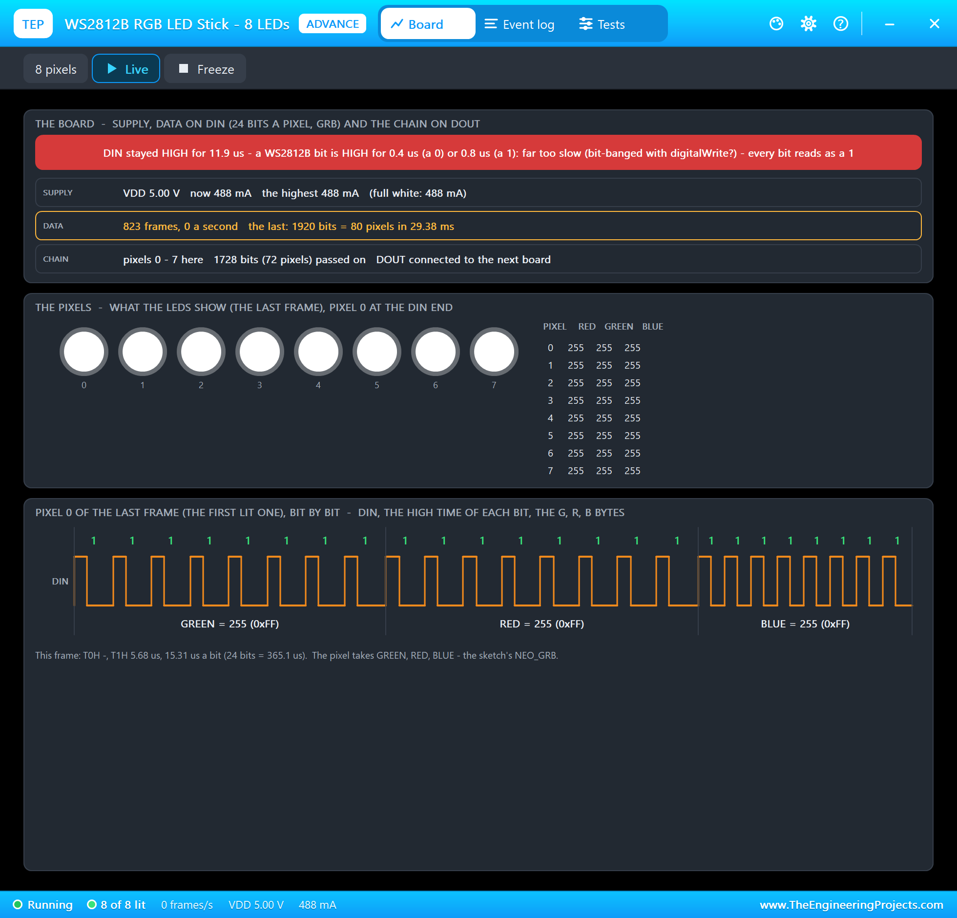
On node 2 the same frame of 80 pixels, 1920 bits, takes 29.38 ms instead of 2.4 ms. The Board page shows the warning in its banner, every pixel at 255, 255, 255, and pixel 0 with 24 ones: "T0H -, T1H 5.68 us, 15.31 us a bit". There is not a single 0 left in the frame. The log shows the warning for the stick and for the matrix behind it:
NEO2: DIN stayed HIGH for 11.9 us - a WS2812B bit is HIGH for 0.4 us (a 0) or 0.8 us (a 1): far too slow
      (bit-banged with digitalWrite?) - every bit reads as a 1 at 33.1373 s
NEO3: DIN stayed HIGH for 11.9 us - a WS2812B bit is HIGH for 0.4 us (a 0) or 0.8 us (a 1): far too slow
      (bit-banged with digitalWrite?) - every bit reads as a 1 at 33.1373 s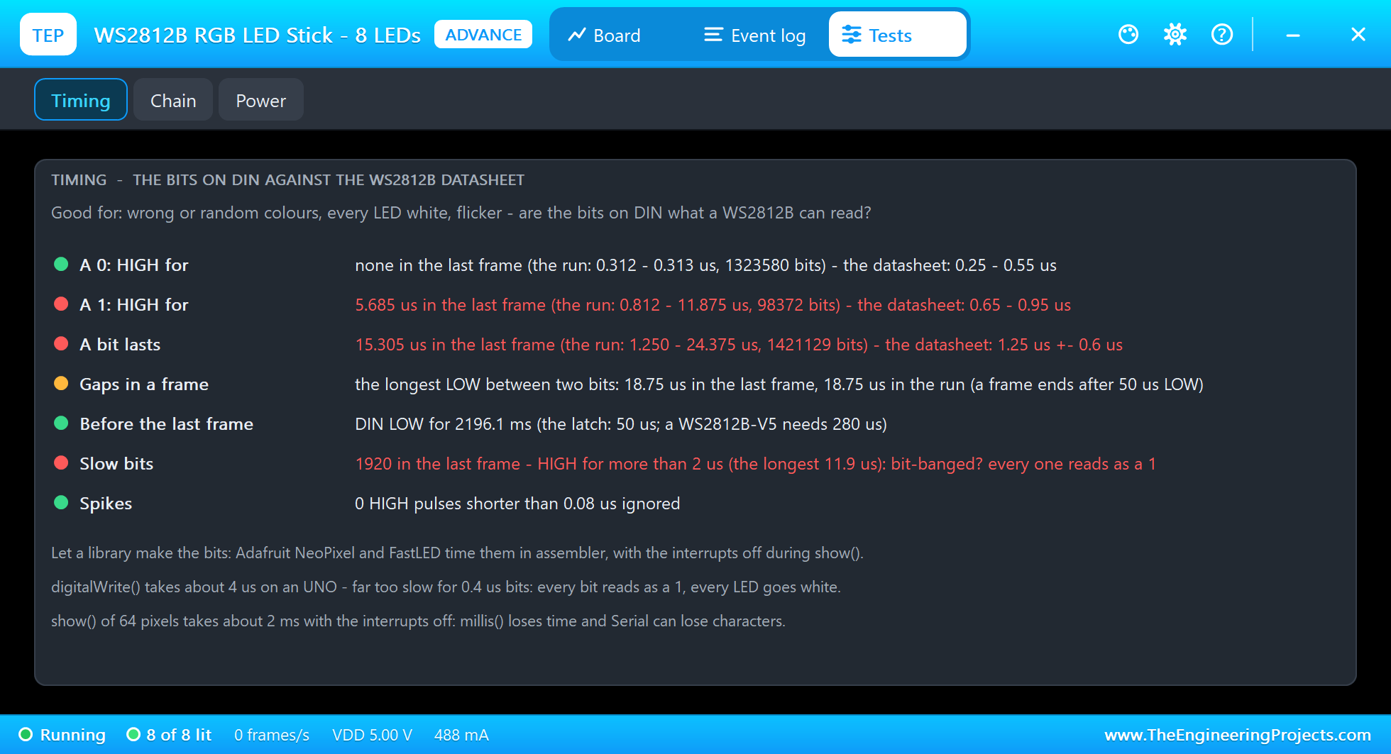
The Timing tool measures the last frame against the datasheet: no 0s at all, the 1s HIGH for 5.685 us against 0.65 to 0.95 us, a bit lasting 15.305 us, and 1920 slow bits, every bit of the frame HIGH for more than 2 us. In brackets it shows the whole run so far: the 0s from 0.312 to 0.313 us, the 1s from 0.812 to 11.875 us. Type RUN, and the Adafruit library takes over again:
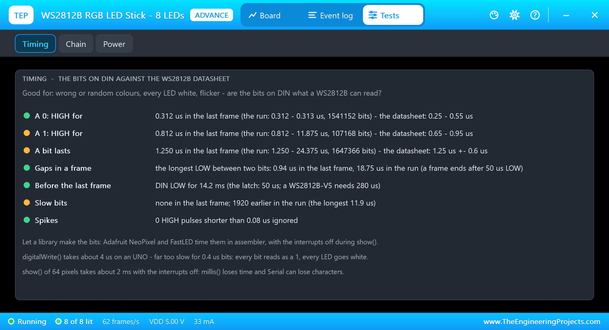
Now the last frame is perfect: the 0s HIGH for 0.312 us, the 1s for 0.812 us, 1.250 us a bit, the longest gap inside the frame 0.94 us, and DIN LOW for 14.2 ms before the frame, far more than the 50 us latch. The amber rows say that the run is not clean: 1920 slow bits came earlier, the longest 11.9 us. The notes under the rows give the cure: let a library make the bits. Adafruit NeoPixel and FastLED time them in assembler, with the interrupts off.
The Simulation Log
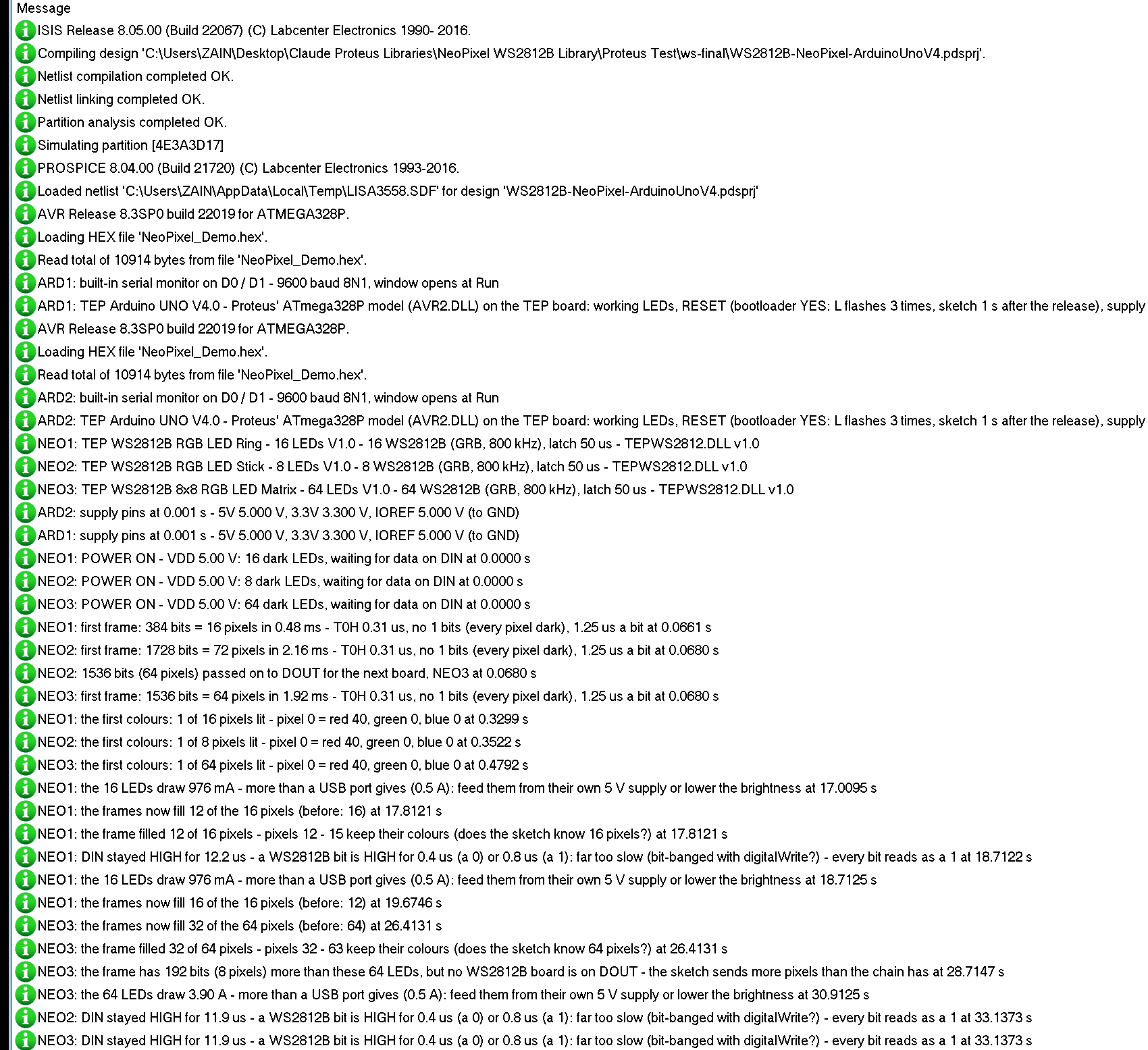
Every board also writes to the simulation log of Proteus, with the exact simulation time. The start of the run shows how the chain works:
NEO1: POWER ON - VDD 5.00 V: 16 dark LEDs, waiting for data on DIN at 0.0000 s
NEO1: first frame: 384 bits = 16 pixels in 0.48 ms - T0H 0.31 us, no 1 bits (every pixel dark), 1.25 us a bit at 0.0661 s
NEO2: first frame: 1728 bits = 72 pixels in 2.16 ms - T0H 0.31 us, no 1 bits (every pixel dark), 1.25 us a bit at 0.0680 s
NEO2: 1536 bits (64 pixels) passed on to DOUT for the next board, NEO3 at 0.0680 s
NEO3: first frame: 1536 bits = 64 pixels in 1.92 ms - T0H 0.31 us, no 1 bits (every pixel dark), 1.25 us a bit at 0.0680 s
NEO1: the first colours: 1 of 16 pixels lit - pixel 0 = red 40, green 0, blue 0 at 0.3299 s
The first frame comes from setup(): every pixel dark, so there are no 1 bits, and the bits of a 0 measure 0.31 us. On node 2 the stick keeps 192 bits and passes 1536 on, and the matrix gets its first frame of exactly those 1536 bits in the same moment. The ring of 16 needs 384 bits, 0.48 ms; the chain of 72 needs 1728 bits, 2.16 ms.
How the Model Works
Proteus runs the Arduino's writes to D6 as digital events, each with its exact time. The model takes every rising and falling edge on DIN and measures the HIGH time of each pulse. Like the real chip, it decides at 0.6 us: shorter is a 0, longer is a 1. A HIGH shorter than 0.08 us is a spike and is ignored; a HIGH longer than 2 us counts as a slow bit. The bits fill the pixels 24 at a time in GRB order, and once all of this board's pixels are full, every further edge is repeated on DOUT 0.25 us later, so the next board sees the same bit times.
At every falling edge the model sets a timer for the latch time. If no new rising edge comes before it runs out, the frame is over: the LEDs show their new colours, the panel and the pop-up update, and the model checks the frame for every mistake. The current of the LEDs goes back into the circuit at the next analog step, as a load between 5V and GND, so the supply really carries it. Which board is on DOUT the model finds from the wire itself, at the first edge on DIN.
Troubleshooting
- Nothing lights: DIN is not connected, there is no 5V (the PWR LED is dark), the sketch never calls
begin()andshow(), or it uses the wrong pin. - Red shows green and green shows red: the colour order. A WS2812B takes green, red, blue: use
NEO_GRB. - Every LED is white: the bits are too slow. The Timing tool shows the HIGH times; use the Adafruit NeoPixel or the FastLED library.
- The last pixels stay dark or keep old colours: the pixel count of the sketch is smaller than the chain. The Chain tool shows it.
- The next board does nothing: its DIN is not connected to the DOUT before it, or the pixel count of the sketch covers only the first board.
- Whites turn yellow or the Arduino resets: too much current. Lower the brightness or use a separate 5 V supply; the Power tool shows the current.
- No part, no LEDs or no monitor: TEPWS2812.DLL or TEPARDUINO.DLL is missing from MODELS and the project folder; a closed monitor opens again with a click on the UNO's USB port.
Things to Know Before Using Real WS2812B LEDs
- Mind the current: up to 60 mA per LED at full white, so about 1 A for a ring of 16 and 3.9 A for an 8x8 matrix. Feed 5V from its own supply, join the grounds, and keep the brightness down.
- Protect the first LED: a 300 to 500 ohm resistor in the data line near the first LED and a 1000 uF capacitor across 5V and GND.
- 3.3 V boards: DIN needs 0.7 x VDD, 3.5 V, for a HIGH at 5 V. Use a level shifter such as the 74AHCT125, or run the LEDs a little lower.
- show() blocks the interrupts: about 30 us a pixel, so
millis()loses time and Serial can lose characters with long chains. - Long chains: feed 5 V and GND at both ends, or every few hundred LEDs, so the last LEDs do not turn reddish.
Limitations of the Simulation
- Not modelled: the PWM of the LEDs (each colour shows as a steady brightness), the exact intensities of the colours and their shift at low VDD (a warning only), heat, and damage from a wrong supply (the model only warns).
- A real WS2812B rebuilds every bit it passes on to DOUT with clean timing; the model passes the bit times on as they came. That is why NEO3 also reports the slow bits of SLOW; the colours are the same either way.
- DIN is a digital pin in Proteus, so a 3.3 V board shows no problem here; see the hardware notes above.
- Not included: the RGBW LEDs (SK6812) and the 400 kHz WS2811.
- The tabs, the strips, their LEDs and the panels are TEP additions.
- The model is our own, written from the WS2812B datasheet. This library is not made or endorsed by Worldsemi, Adafruit, the makers of these boards or Labcenter.
- Licences: the demo sketch uses the Adafruit NeoPixel library 1.12.3 (LGPL-3.0), which is not shipped; install it from the Library Manager. The demo's HEX file contains it and the Arduino AVR core 1.8.6 with LGPL-licensed code; the source links are in the README.
- Tested in Proteus 8.5 in October 2026 (the demo as shipped on two Arduino UNO V4.0 boards with their built-in monitors: the tour on both nodes, RGB and GRB, WHITE, COUNT 12, COUNT 40, COUNT 80 and SLOW, the pop-up and the three tools, the ring up close; 41.2 s of simulation took 98 s, about 0.4 x real time with the pop-up and both monitors open). Proteus 7 is not supported.
So, that was all about the WS2812B NeoPixel Library for Proteus V1.0. I hope the GRB order, the bits of 0.4 and 0.8 us, the chain on DOUT and the current of these little LEDs are clear now, so your rings and matrices light up the right colours from the first run. If you use the WS2812B NeoPixel Library for Proteus in a project, please share it in the comments or in our forum, and if you have any questions, ask in the comments and I will help you out. Till the next tutorial, take care and have fun!