Hello friends, I hope you all are doing great. Today, I am going to share the IoT People Counter with Raspberry Pi 5 - Proteus Simulation, the thirty-sixth project of our IoT Projects series. If you have searched for a Proteus simulation of a Raspberry Pi people counter with infrared beams, here is a complete one. A Raspberry Pi 5 watches two infrared beams across a doorway, tells from the order they are broken whether someone walked in or out, keeps the number of people inside, clicks a real electromechanical counter for every visitor, lights a FULL lamp at the room's limit, and serves a live web dashboard that you can open on a laptop or a phone.
Shops, libraries, meeting rooms and buses all want to know how many people are inside, and the classic way is a pair of light beams across the door. One beam can count, but it cannot tell in from out; two beams a hand's width apart can, because whoever walks through breaks them one after the other, and the order gives the direction. In this tutorial, we will go through the circuit, learn how an IR LED and a photodiode make a beam, measure the photodiode with an ADS1115, turn the beams' order into a direction with a small state machine, drive an electromechanical counter through an H-bridge, walk through the Python program, and then run the simulation: four people in, the room full, one out, a hand through one beam, and the dashboard. At the end, you can download the project with the program, every library file and the Python runtime the Pi needs.
NOTICE: Our team has put a lot of effort into this project: the circuit, the code and every part in the simulation are our own work, and you get them all free. Your feedback is the fuel that keeps us going, so please tell us what you think in the comments below. And if our free projects help you, you can buy us a coffee. So, let's get started with the IoT People Counter with Raspberry Pi 5 - Proteus Simulation:
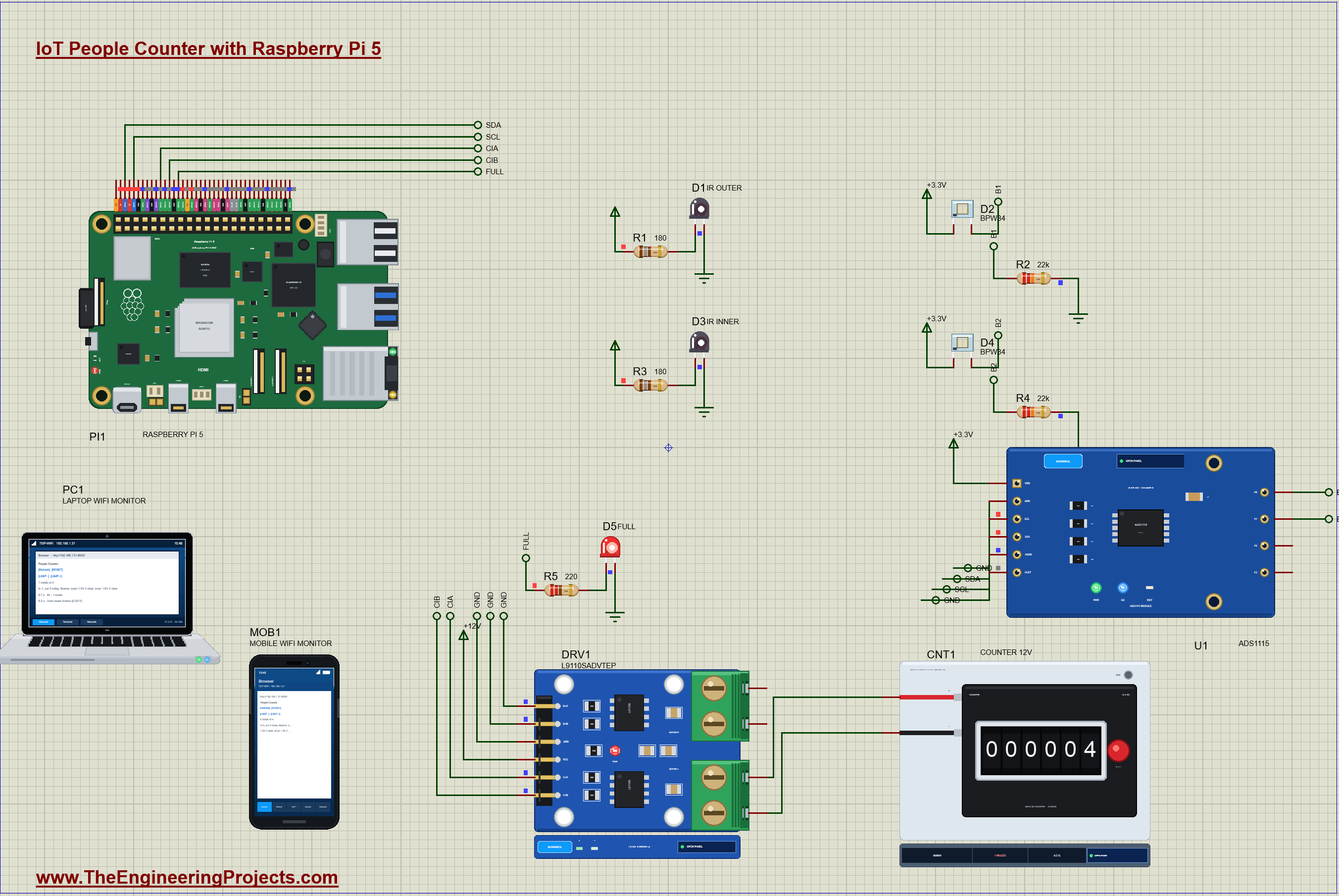
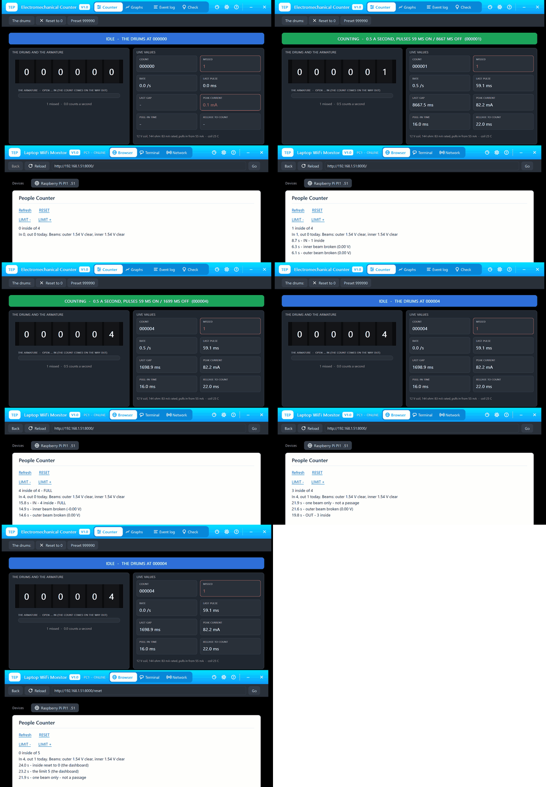
What Does This People Counter Do?
- Two beams across a doorway: each an infrared LED shining on a BPW34 photodiode, 10 cm apart.
- Knows the direction: the outer beam first means IN, the inner beam first means OUT.
- Ignores false alarms: a hand or a bag that breaks one beam only does not count.
- Keeps the number inside: and the visitors in and out today.
- A real click counter: an electromechanical counter adds one for every visitor and keeps its total.
- FULL lamp: a red LED lights when the room reaches its limit.
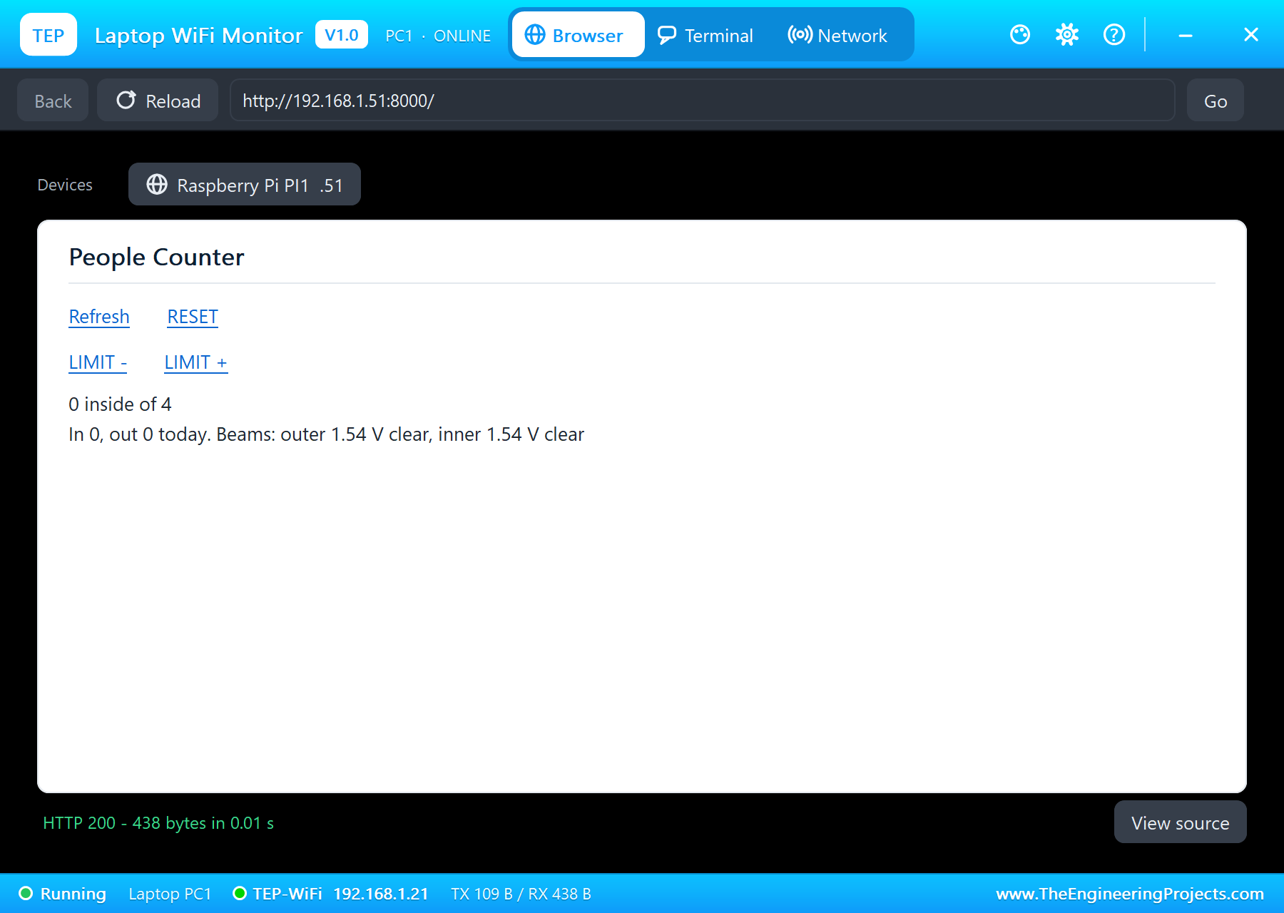
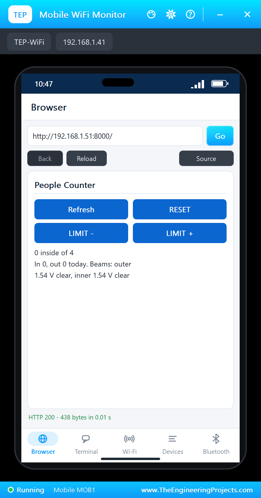
- A dashboard: the count, the limit, both beams' voltages, RESET and LIMIT from a laptop or a phone.
It is a great project for learning how light sensors are read, how to turn sensor signals into events with a state machine, and how to switch a coil safely. In the simulation, the photodiodes' pop-ups set the light on them, Bright when the beam reaches them and Dark when someone blocks it, and the counter's pop-up shows its drums turning.
Components Used in the Proteus Simulation
All the parts come from our Proteus libraries, each with its own tutorial. The project zip at the end includes every LIB and DLL file.
| Part | Proteus device | Library post | Connection |
|---|---|---|---|
| Raspberry Pi 5 | RASPBERRY PI 5 | Raspberry Pi 5 Library for Proteus | PI1, Ethernet 192.168.1.51 |
| IR LED 940 nm x 2 | IRLED5MM940TEP | IR LED Library for Proteus | D1 outer, D3 inner |
| BPW34 photodiode x 2 | PHOTODIODEBPW34TEP | Photodiode Library for Proteus | D2 outer, D4 inner |
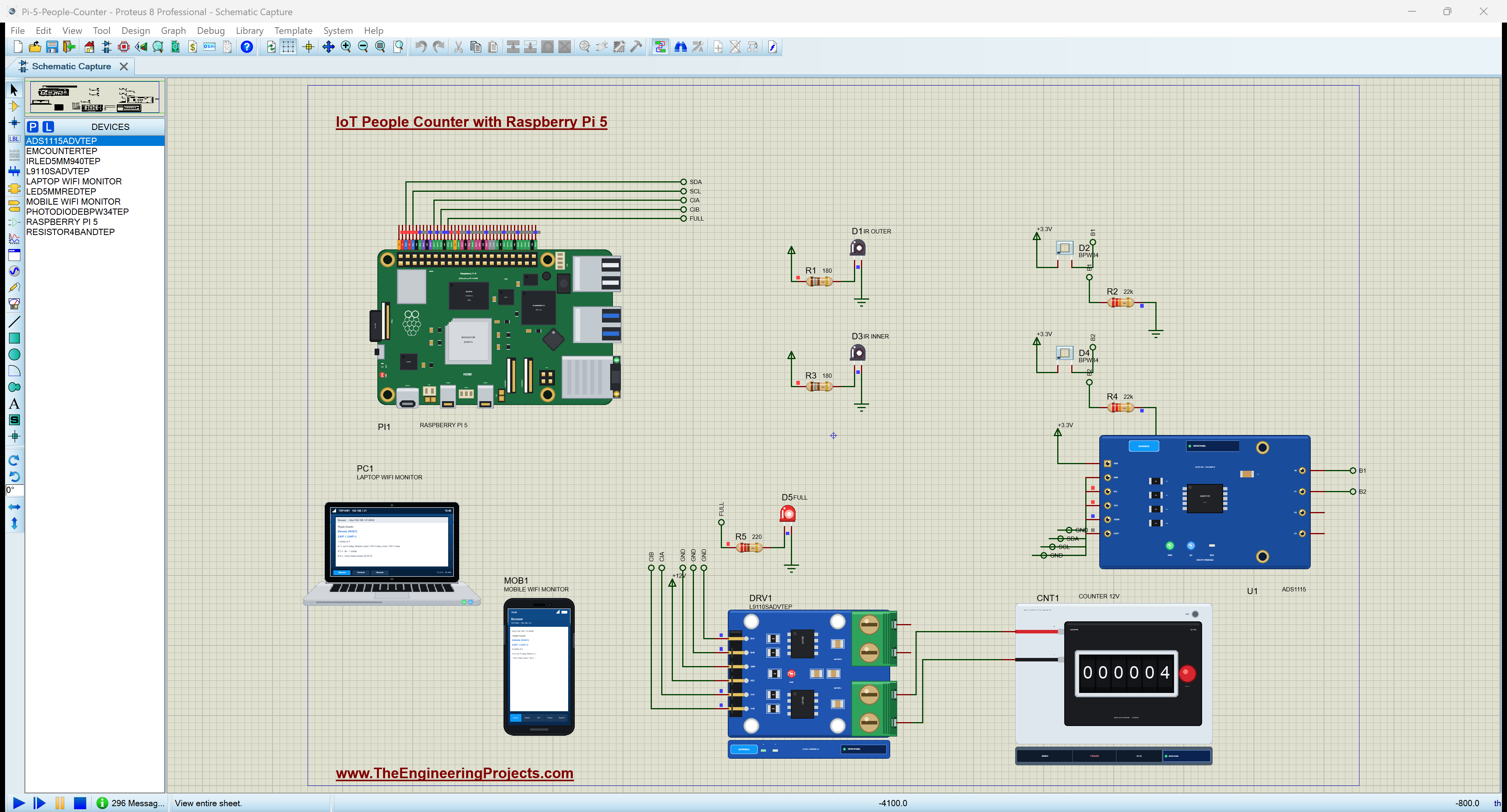
| ADS1115 16-bit ADC | ADS1115ADVTEP | ADS1115 ADC Library for Proteus | U1, I2C1 at 0x48 |
| Electromechanical counter, 12 V | EMCOUNTERTEP | Electromechanical Counter Library for Proteus | CNT1, on the L9110S |
| L9110S H-bridge | L9110SADVTEP | L9110S Motor Driver Library | DRV1, GPIO17 / GPIO27 |
| Red LED FULL | LED5MMREDTEP | 5mm LED Library | D5, GPIO22 |
| Resistors 180, 22k, 220 ohm | RESISTOR4BANDTEP | Resistor Library | R1 - R5 |
| Laptop WiFi Monitor | LAPTOP WIFI MONITOR | Laptop WiFi Monitor | PC1 |
| Mobile WiFi Monitor | MOBILE WIFI MONITOR | Mobile WiFi Monitor | MOB1 |
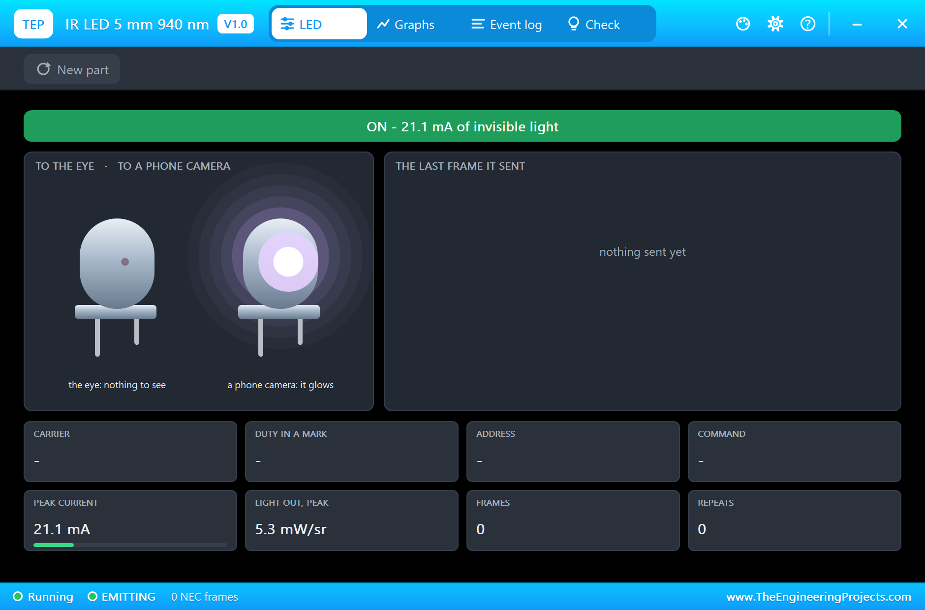
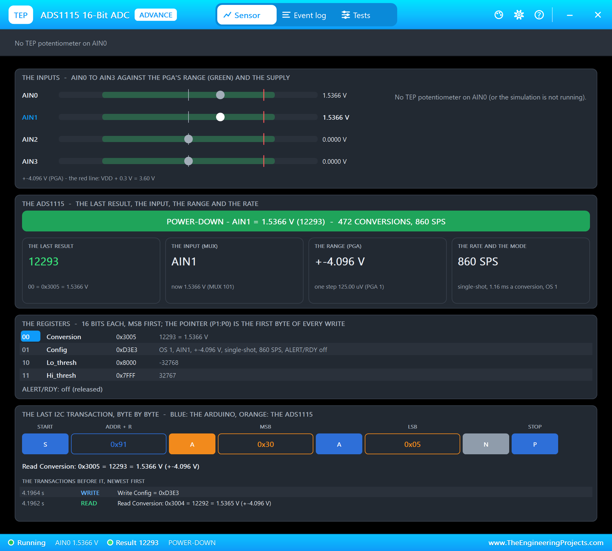
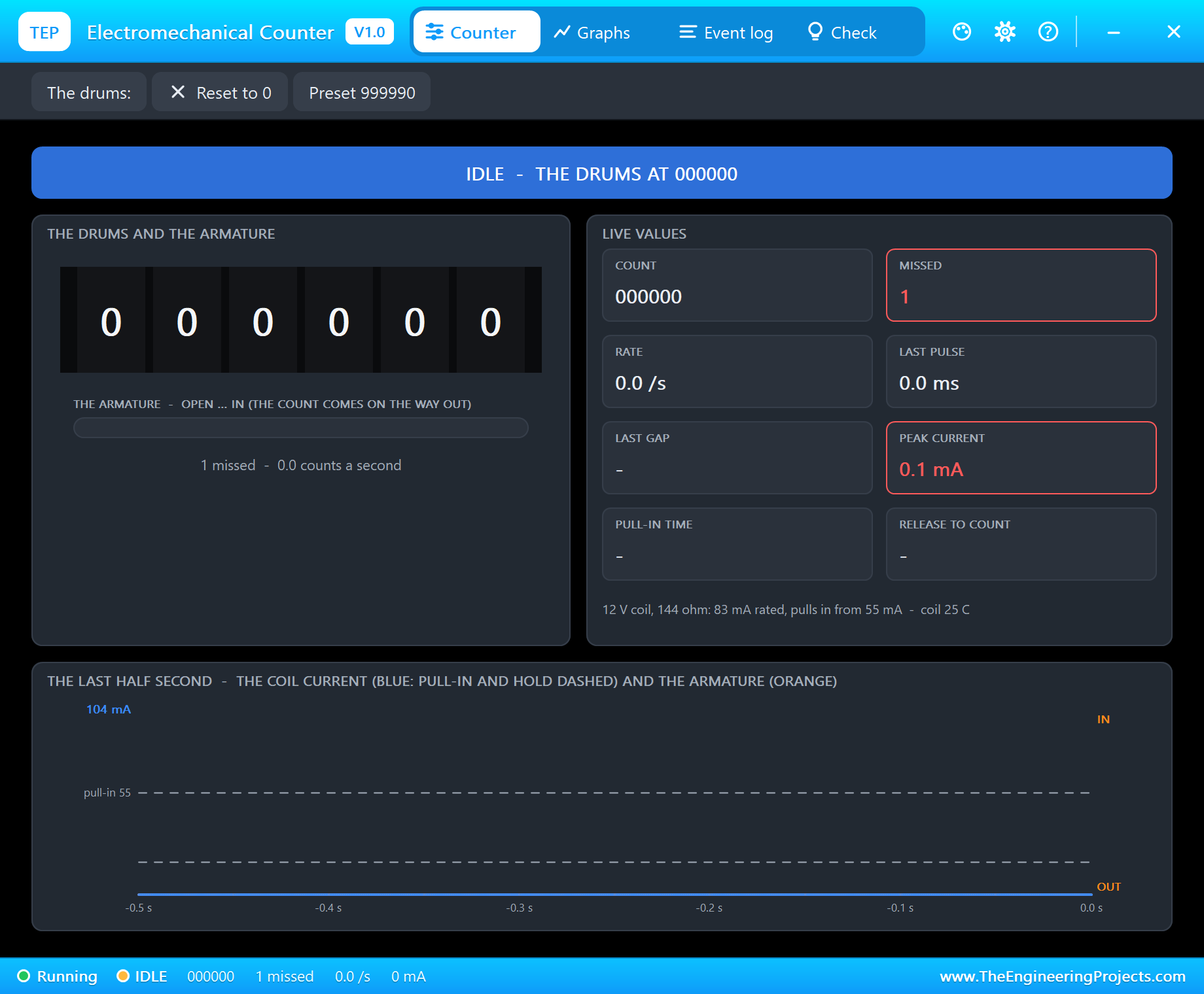
The photodiodes, the IR LEDs, the ADS1115, the L9110S and the counter are models with pop-ups. A photodiode's pop-up sets its light, from Dark to Daylight, and shows its photocurrent. An IR LED's pop-up shows its invisible light to the eye and to a phone camera. The ADS1115's pop-up shows its four inputs and every conversion. The counter's pop-up shows its six drums, the armature and the coil's current.
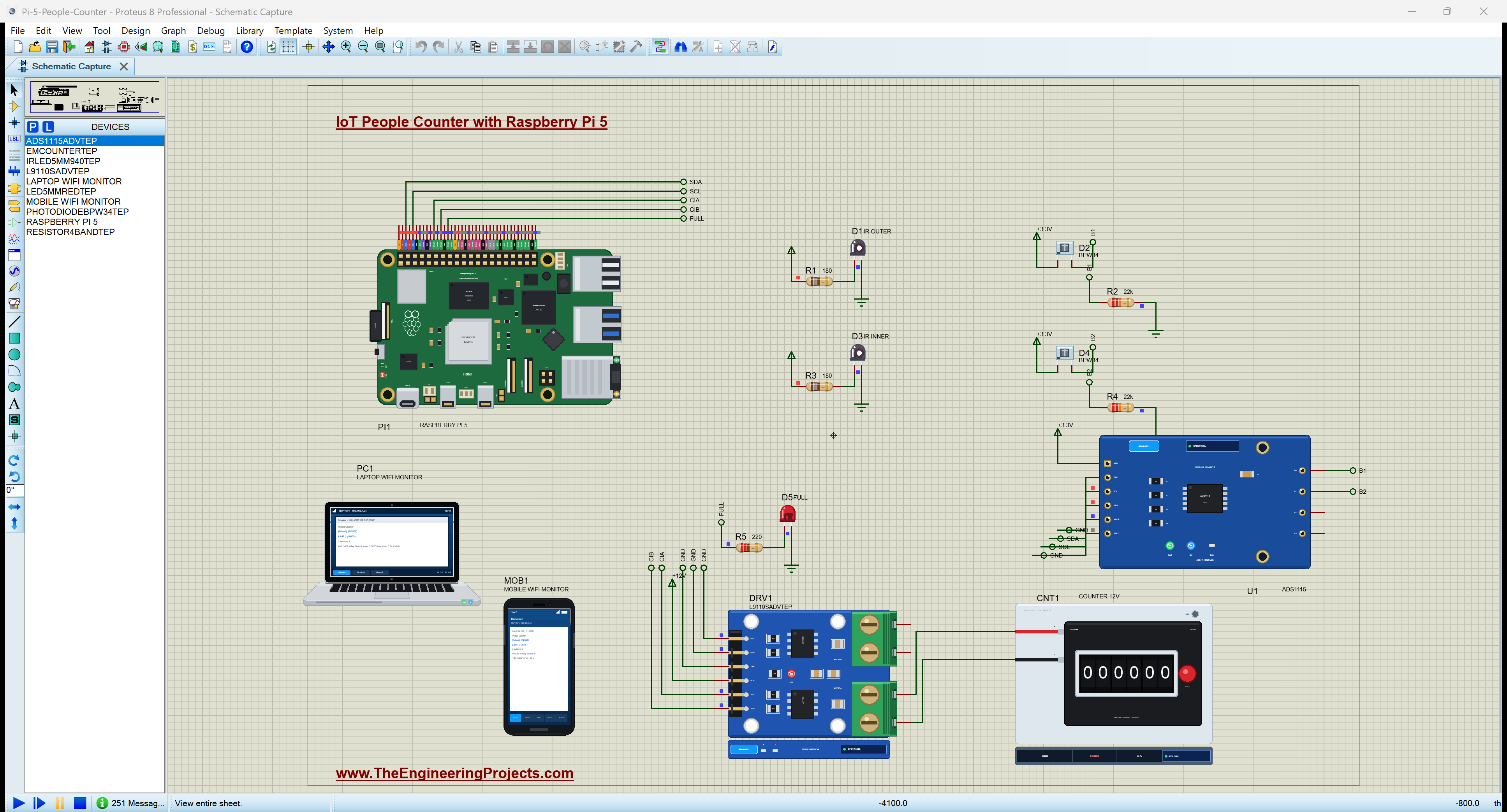
Proteus Simulation of the People Counter: the Circuit
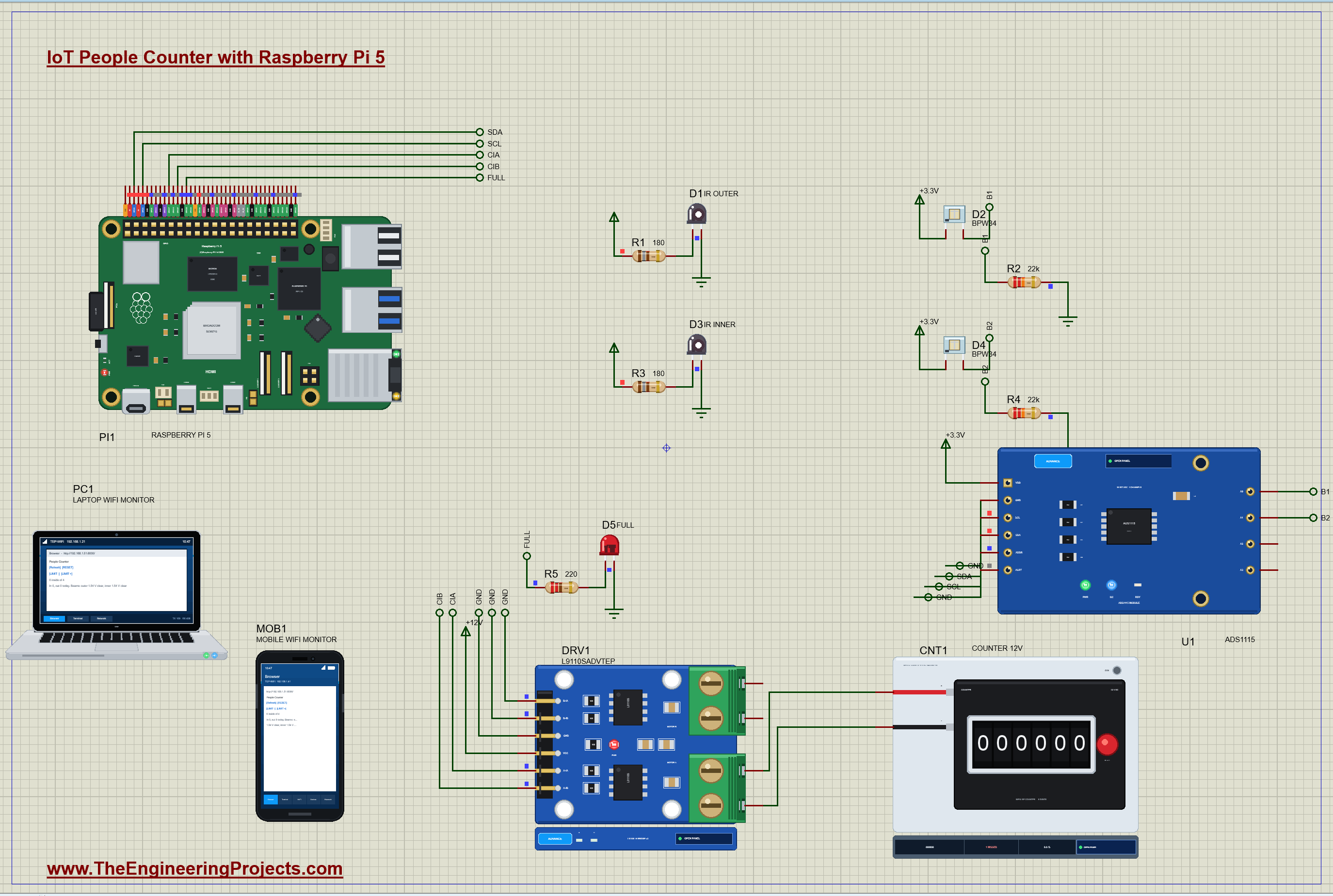
| Part | Pins | Raspberry Pi 5 header / other |
|---|---|---|
| D1 / D3 IR LEDs | A / K | the 5 V rail through R1 / R3 180 ohm / GND |
| D2 / D4 photodiodes | K / A | +3.3V / the nets B1 / B2, R2 / R4 22 kohm to GND |
| U1 ADS1115 | VDD / GND / SDA / SCL / ADDR / A0 / A1 | +3.3V / GND / GPIO2 (pin 3) / GPIO3 (pin 5) / GND / B1 / B2 |
| DRV1 L9110S | A-IA / A-IB / VCC / B-IA, B-IB | GPIO17 (pin 11) / GPIO27 (pin 13) / +12V / GND |
| CNT1 counter | + / - | the L9110S's A-OA / A-OB |
| D5 FULL | A / K | GPIO22 (pin 15) through R5 220 ohm / GND |
Each IR LED takes about 20 mA from 5 V through 180 ohm: (5 - 1.3) / 180 = 21 mA, a bright invisible beam. The photodiodes face them across the doorway. The counter's coil wants 12 V and 83 mA, far more than a GPIO pin, so the L9110S switches it, and the Pi only sends a logic pulse.
How the People Counter Works
An Infrared Beam
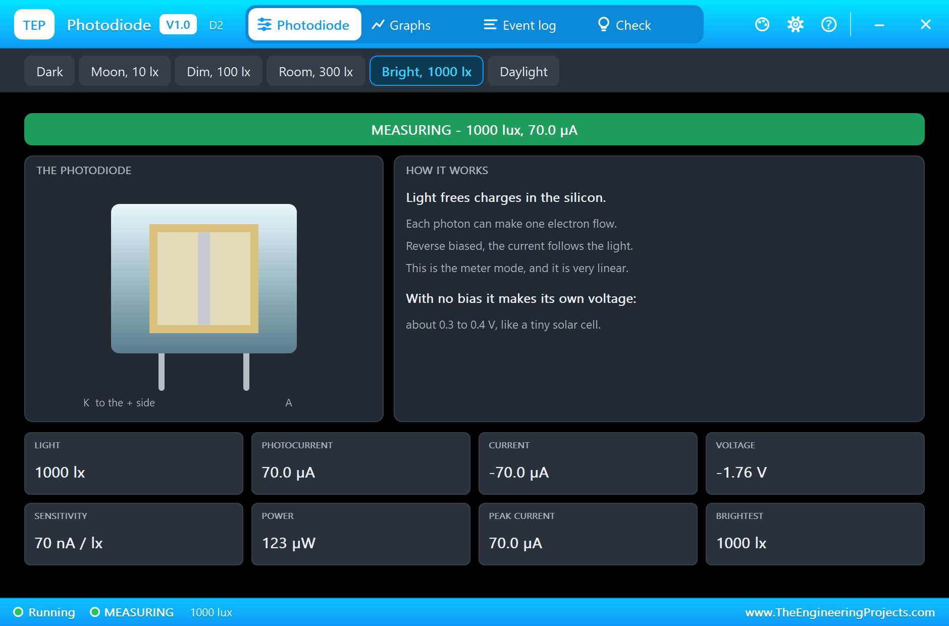
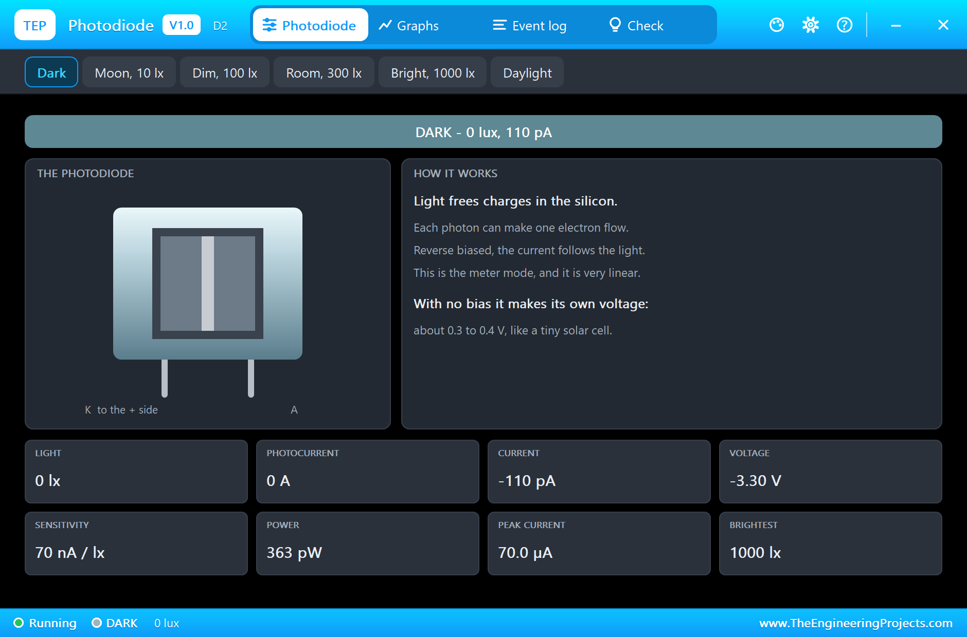
A 940 nm infrared LED makes light that we cannot see but silicon sees very well. The BPW34 photodiode turns light into current: about 70 nanoamperes for every lux, in a straight line from darkness to bright light. Reverse biased, its cathode on 3.3 V, it pushes that current through a 22 kohm load resistor to ground, and the voltage across the resistor follows the light. Worked example: with the beam on it the photodiode sees about 1000 lux, 70 microamperes, and 70 uA x 22 kohm = 1.54 V. When a body blocks the beam it sees almost nothing, and the voltage falls to nearly 0 V. Infrared is chosen because it is invisible and easy to keep apart from room light; a real counter also pulses its LEDs and looks for the pulses.
Reading the Beams with an ADS1115
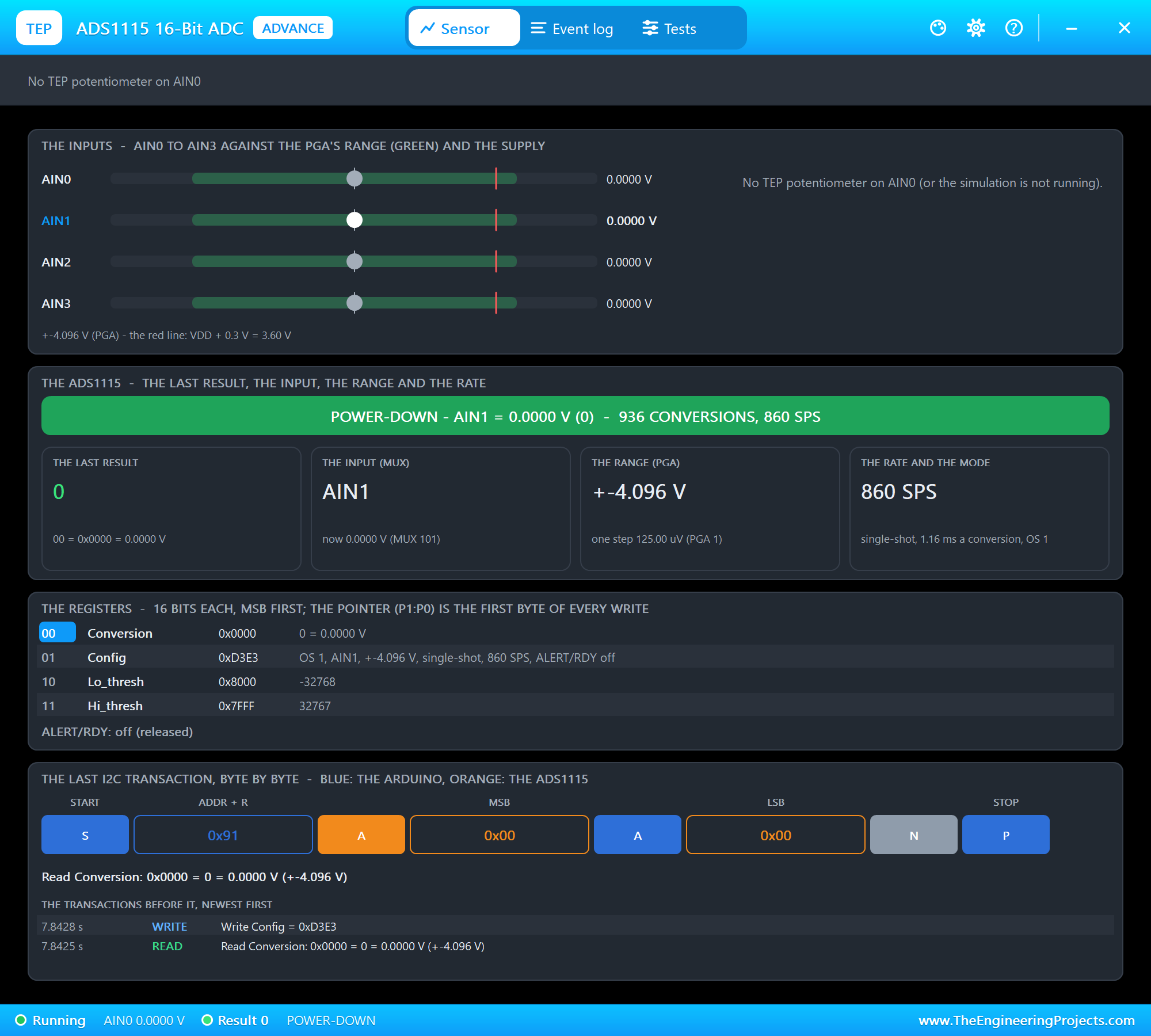
The Raspberry Pi has no analog input, so an ADS1115 measures both photodiode voltages: A0 for the outer beam and A1 for the inner beam. The program starts a single conversion of one input, waits two milliseconds at 860 samples a second, reads it, and does the same for the other: both beams are read every 15 ms or so, far faster than anyone walks. A beam counts as BROKEN below 0.40 V and as clear again only above 0.70 V; this gap, the hysteresis, stops a reading that hovers around one threshold from flickering between the two states.
Which Way? A Small State Machine
Someone walking in breaks the outer beam first, then, a moment later, the inner beam too, then clears the outer and finally the inner. Someone walking out does the same in the opposite order. So the program keeps a list of the beams in the order they were broken during one passage, and when both are clear again it decides: [outer, inner] is IN, [inner, outer] is OUT, and anything else, a hand that broke the outer beam alone, counts nothing. Worked example: a person 40 cm deep walking at 1 m/s blocks each beam for about 0.4 s, and the two breaks overlap for about 0.3 s: plenty of readings at 15 ms each.
Driving an Electromechanical Counter
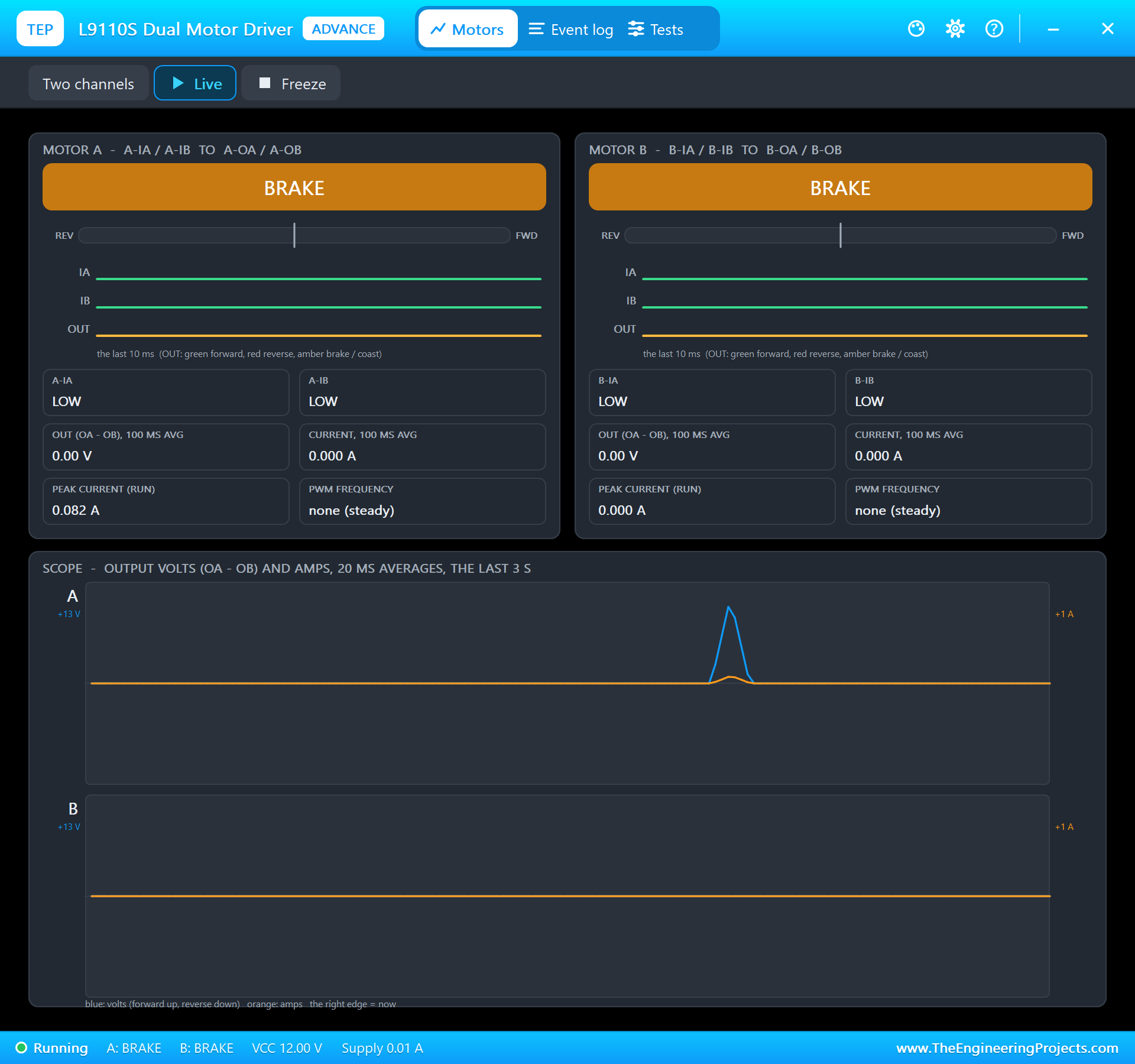
The counter is the panel counter of factory machines: six number drums behind a window and a coil. Each pulse pulls an armature in; when the pulse ends, a spring throws it back and a ratchet moves the drums on by one. It needs at least 16 ms to pull in and about 22 ms to count on the way out, and it keeps its count with the power off. The program sends a 60 ms pulse: A-IA high and A-IB low, then both low. With both inputs low the L9110S shorts the coil through its lower transistors, and the coil's energy dies away in that loop instead of kicking up a high voltage: the same job a free-wheel diode does across a coil switched by a transistor.
The Python Code Explained
The whole program is included in the download. It uses lgpio for the GPIO pins and the I2C bus, a thread for the beams, and the standard library's http.server for the dashboard. At the top are the pins and the thresholds:
BLOCKED_V, CLEAR_V = 0.40, 0.70                       # V: a beam is broken below 0.40 V, back above 0.70 V (hysteresis)
PULSE_S = 0.06                                        # the counter's coil pulse (it needs 16 ms to pull in, 22 ms to count on release)
LIMIT = 4                                             # people allowed in the room (the dashboard changes it)
The ADS1115
        mux = 0x4 + ch                                     # AINx against GND
        lgpio.i2c_write_i2c_block_data(self.h, 0x01, [0x80 | mux << 4 | 0x03, 0xE3])   # start, +-4.096 V, single shot, 860 SPS
return int.from_bytes(bytes(b), 'big', signed=True) * 4.096 / 32768The first byte of the configuration register sets bit 15, which starts one conversion, puts the input selection in bits 14 to 12, and picks the +-4.096 V range and single-shot mode. The second byte, 0xE3, sets 860 samples a second and switches the comparator off. The result comes back as a signed 16-bit number, so one step is 4.096 / 32768 = 0.125 millivolts: far finer than we need, but the same chip would also let you measure a weak beam across a wide gate. Worked example: a beam on reads 1.537 V, about 12,300 steps; the 0.40 V threshold is 3,200 steps, so the margin between a clear beam and a broken one is huge, and dust on a lens or an ageing LED that loses a third of its light still leaves the beam well above 0.70 V.
The Beams and the Direction
                if not was[k] and v[k] < BLOCKED_V:
                    s['broken'][k] = True
                elif was[k] and v[k] > CLEAR_V:
                    s['broken'][k] = False
if order and not any(now): # the passage is over: both beams clear
if order == [0, 1]: s['inside'] += 1; s['in'] += 1; inside = s['inside']
pulse_counter() elif order == [1, 0]:The first excerpt is the hysteresis: a clear beam must fall below BLOCKED_V to become broken, and a broken beam must rise above CLEAR_V to become clear again, so a reading of 0.55 V changes nothing either way. Every time a beam becomes broken, the program appends its number to the list order, unless it is already there. The passage ends only when both beams are clear; then the list is compared with [0, 1] and [1, 0]. A list with one entry means someone stepped into the doorway and back out, or waved a hand: the counter stays silent. The inside count never goes below zero, so an OUT on an empty room, which can happen after a RESET, is simply ignored for the count.
The Counter Pulse
lgpio.gpio_write(chip, COUNTER_IA, 1) # A-IA HIGH, A-IB LOW: the coil on lgpio.gpio_write(chip, COUNTER_IA, 0) # both LOW: the bridge brakes the coil (no voltage kick)The FULL Lamp
After every passage and every change of the limit, one small function compares the number inside with the limit and sets the red lamp:
        full = s['inside'] >= s['limit']
    lgpio.gpio_write(chip, FULL_LED, 1 if full else 0)
The pages are / (the dashboard), /reset (inside to 0), /limit_up and /limit_down (the limit) and /data (JSON). The dashboard puts its four links first and stays short, because the WiFi Monitors show one screen of a page.
How to Run the Proteus Simulation
- Download the project zip below and install the library files and the TEPPi folder (the steps are under the download button).
- Open Pi-5-People-Counter.pdsprj from the Proteus Simulation folder. Keep people_counter.py and the DLL files next to it.
- Press Play. Both beams are on: the photodiodes see 1000 lux.
- Walk someone in: in D2's pop-up (the outer beam) press Dark, then Dark in D4's (the inner beam), then Bright in D2's and Bright in D4's. The counter clicks.
- Open the Laptop WiFi Monitor (PC1) or the Mobile WiFi Monitor (MOB1) and press Go.
Simulation Results: the People Counter in Proteus
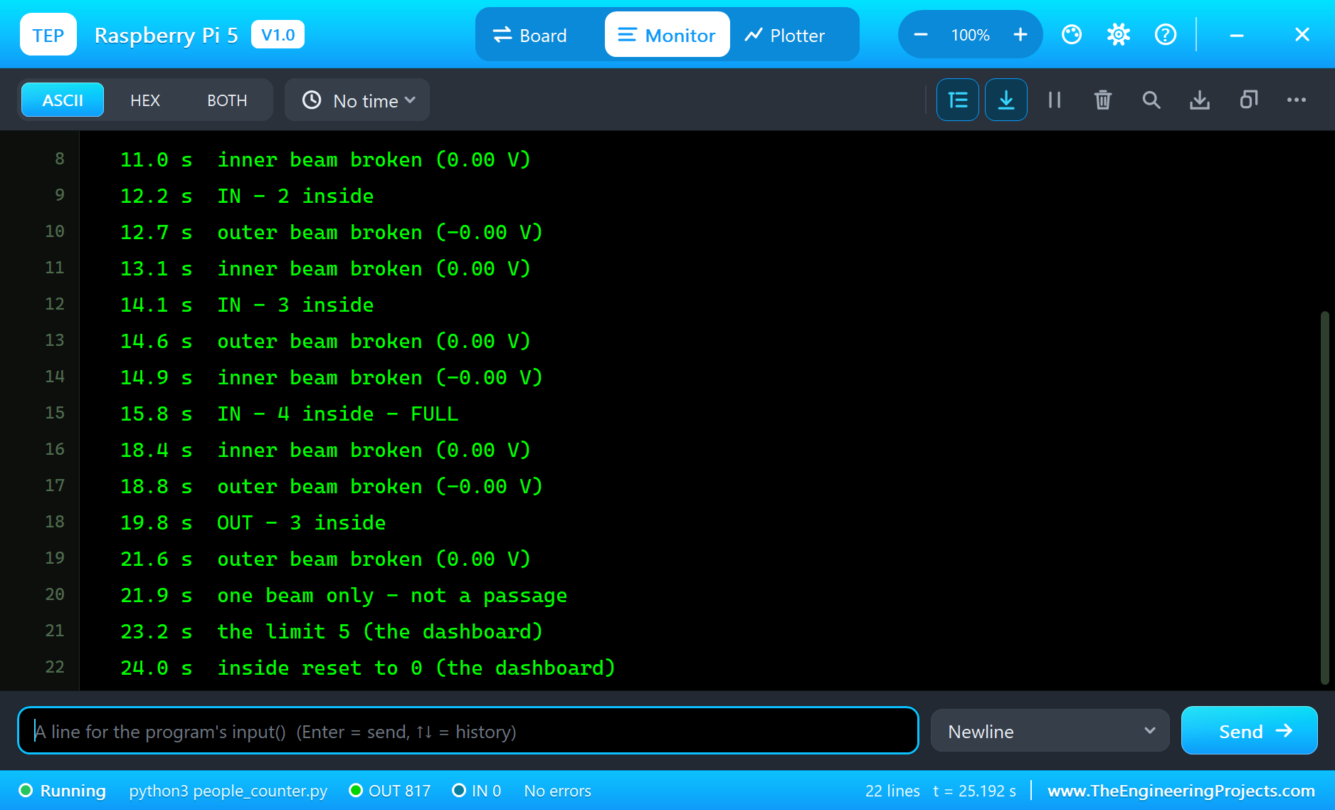
Here is the run that made the screenshots of this tutorial, 25.3 seconds of simulation. The times are the program's own, the seconds since it started, as it printed them in the Pi's terminal.
Both Beams On
At the start both photodiodes see 1000 lux and pass 70.0 microamperes each, and the ADS1115 reads 1.537 V on A0 and A1: exactly the 70 uA x 22 kohm of the worked example. The IR LEDs' pop-up shows their light as a phone camera sees it, a violet glow, while to the eye they look off. The counter shows 000000.
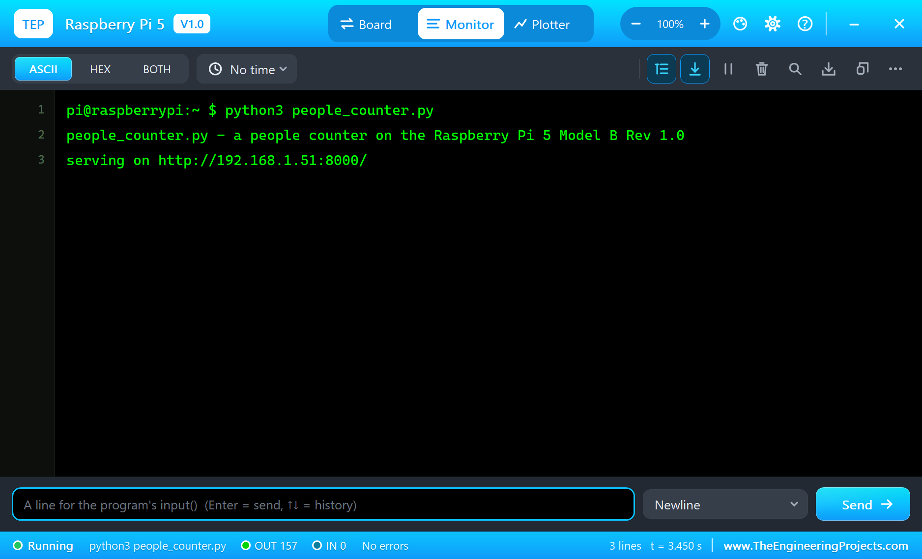
The First Visitor
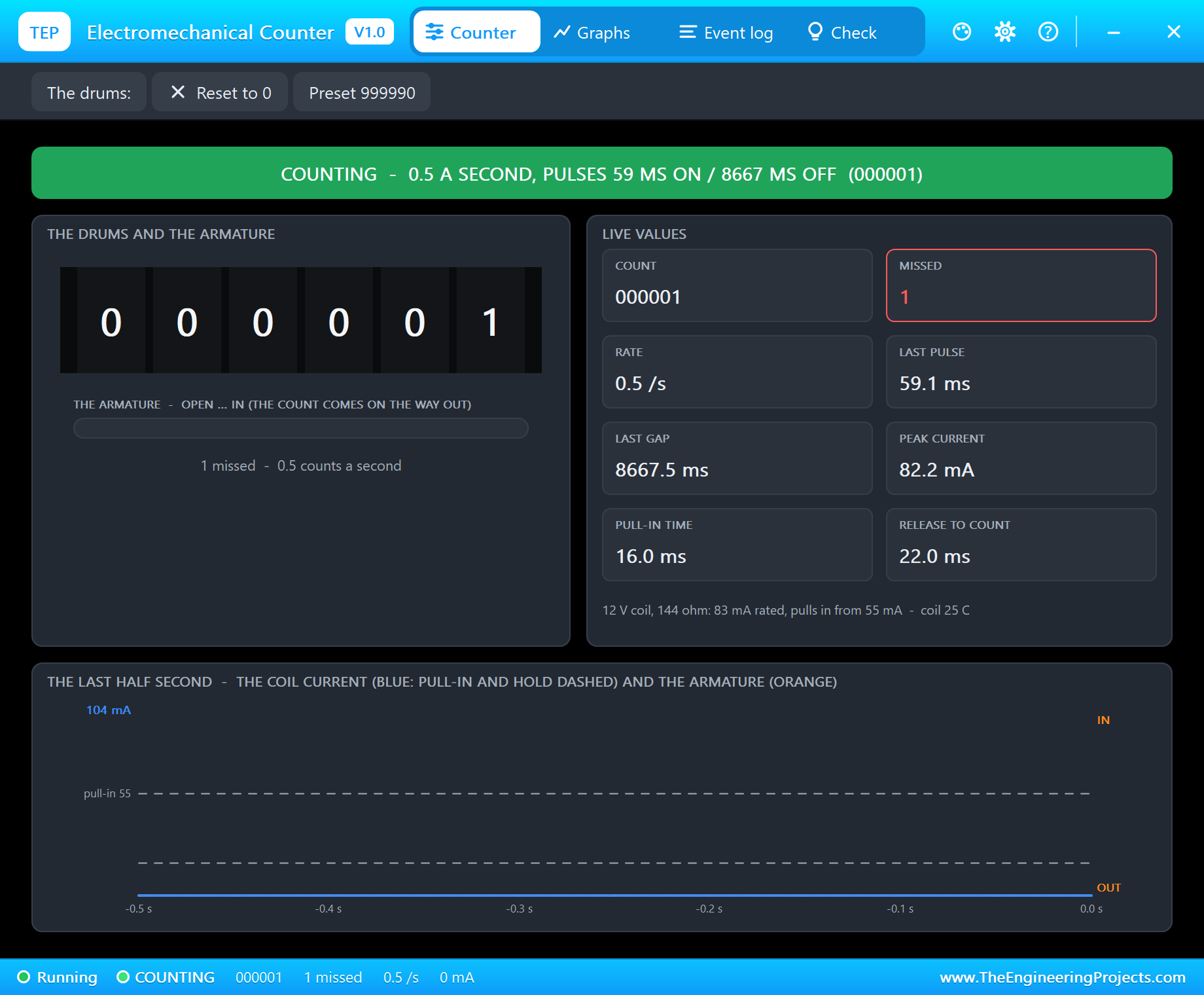
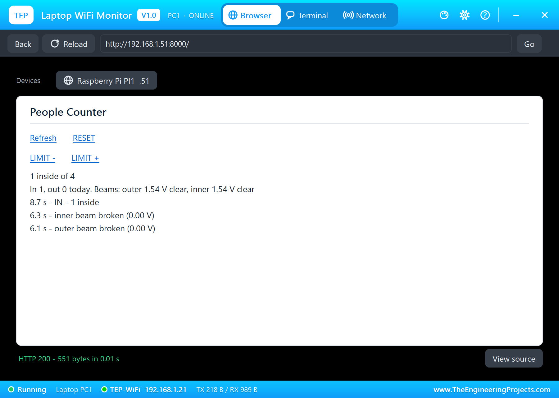
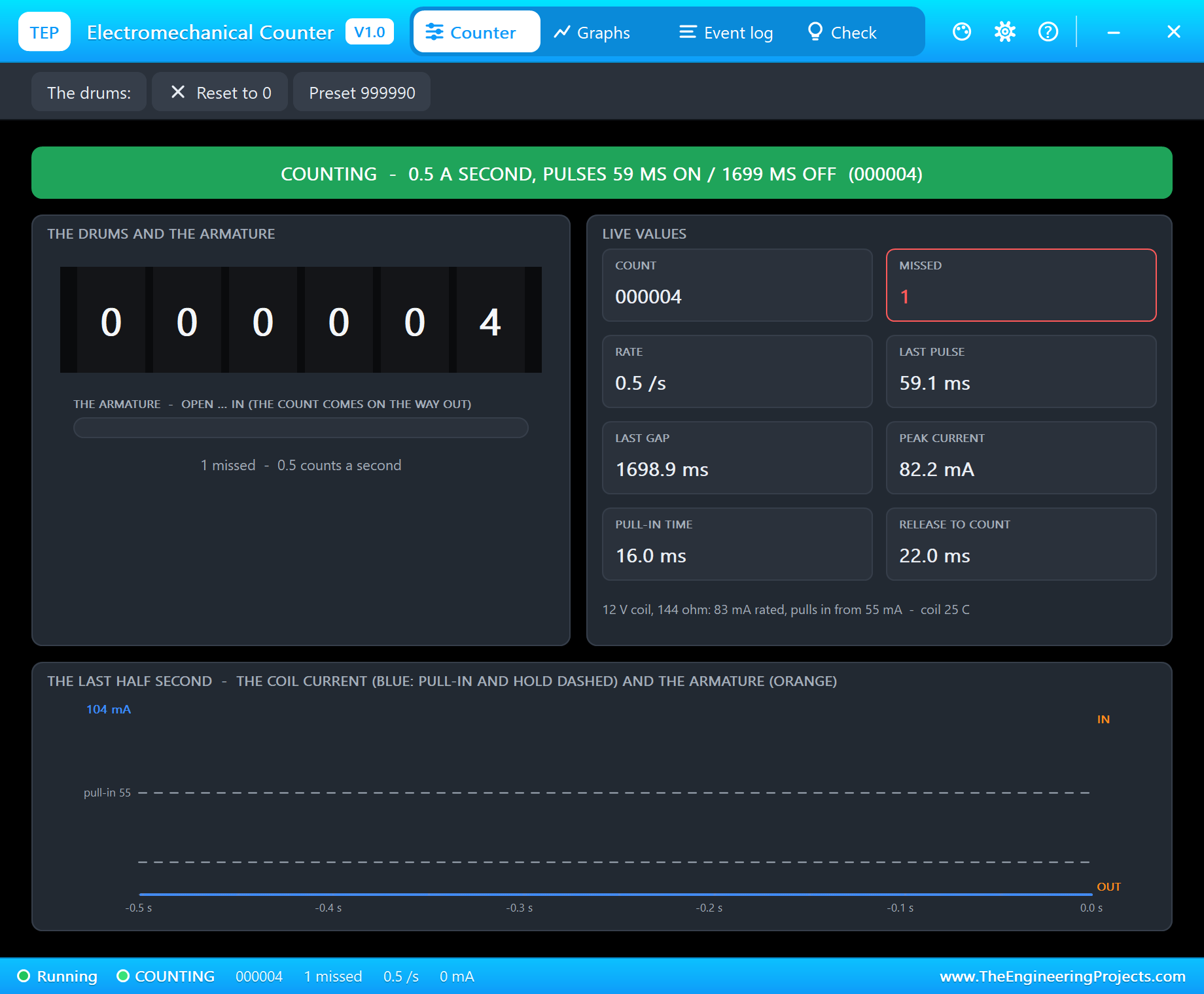
At 6.1 seconds the first person breaks the outer beam: D2 goes dark, and the terminal prints "outer beam broken (0.00 V)". At 6.3 seconds the inner beam goes too, and for a moment both are broken, the person between them. Then the outer clears, then the inner, and at 8.7 seconds the program decides: "IN - 1 inside". The counter gets its pulse, 59.1 ms long: the armature pulls in after 16.0 ms with a peak of 82.2 mA, and 22.0 ms after the pulse ends, as it springs back, the units drum turns to 1.
The Room Fills Up
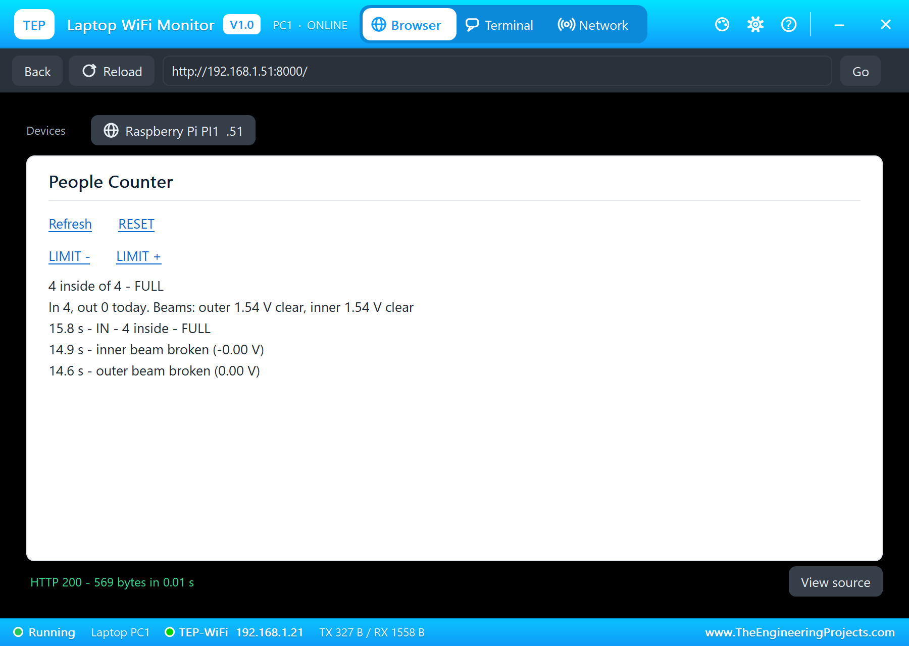
Three more people walk in, at 12.2, 14.1 and 15.8 seconds. With the fourth, the room reaches its limit: "IN - 4 inside - FULL", and the red FULL lamp lights. The counter shows 000004.
Someone Leaves, and a Hand
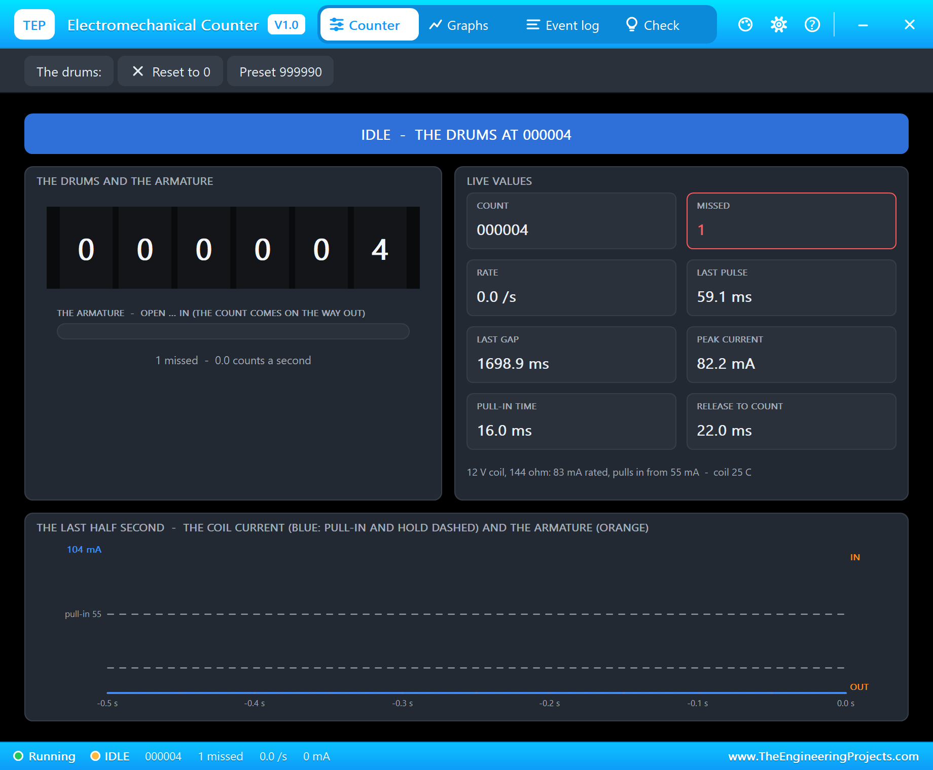
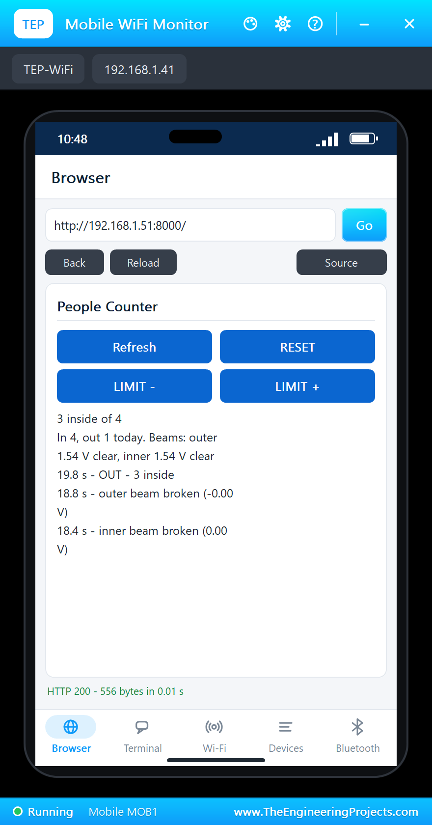
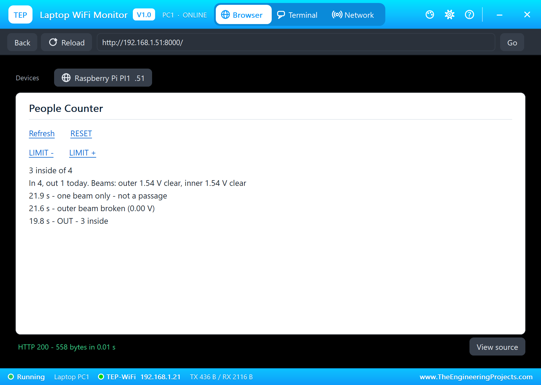
At 18.4 seconds the inner beam is broken first, then the outer one at 18.8: someone is leaving. At 19.8 seconds "OUT - 3 inside", and the FULL lamp goes out. The counter keeps 000004: it counts visitors, and leaving does not take one away, just as a real counter never runs backwards. At 21.6 seconds a hand reaches through the outer beam alone and is pulled back: "one beam only - not a passage", and nothing changes.
The Limit and RESET
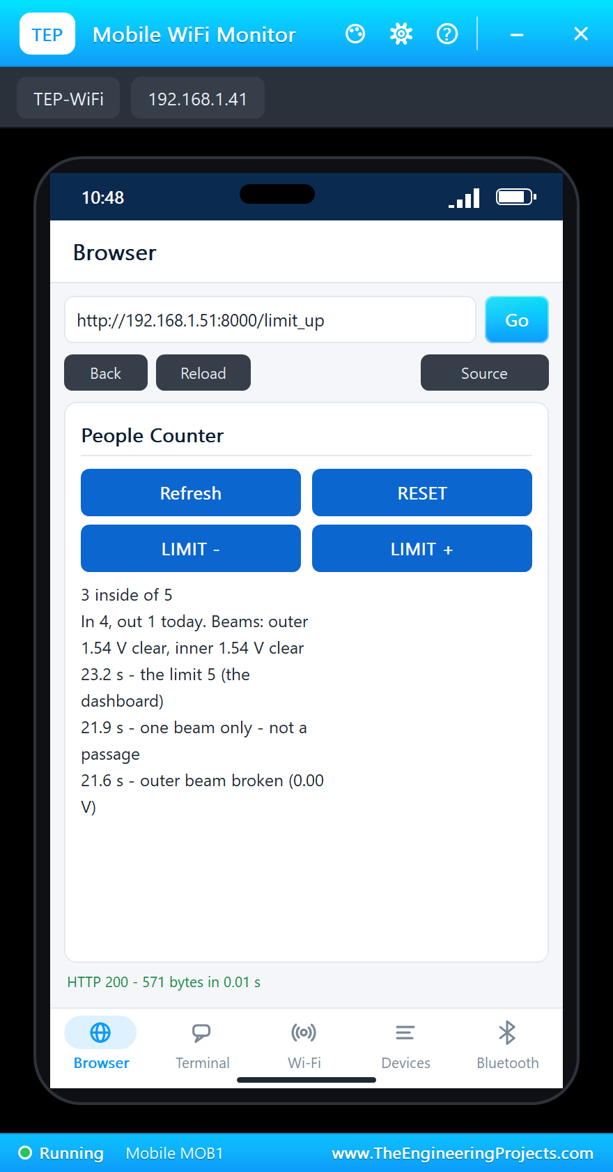
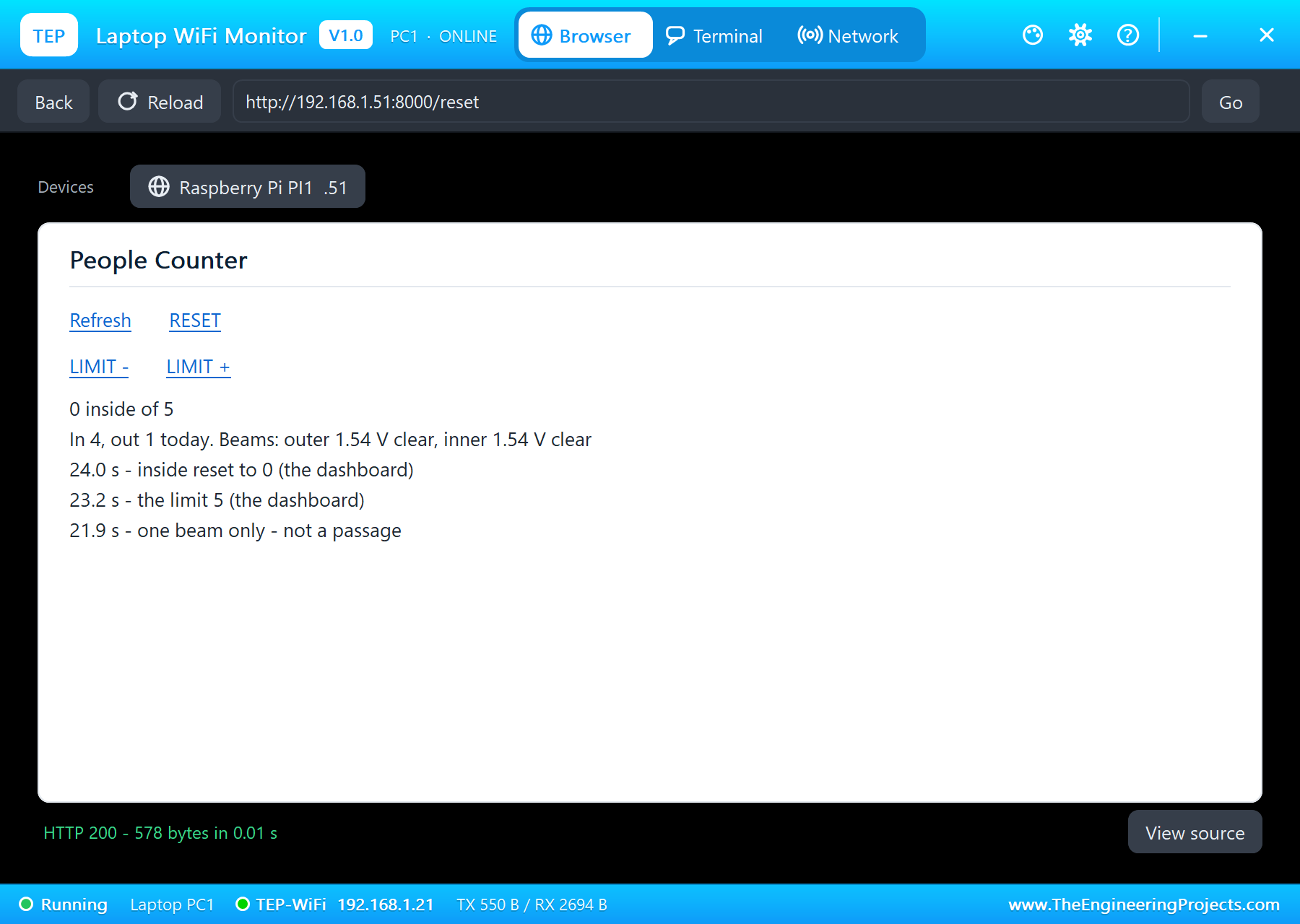
At 23.2 seconds LIMIT + on the phone raises the limit to 5, and at 24.0 seconds RESET on the laptop sets the number inside back to 0 for a new day.
The Numbers of the Run
| What | Result |
|---|---|
| A beam on / blocked | 1.537 V (70.0 uA at 1000 lux) / 0.00 V |
| IN | 8.7, 12.2, 14.1 and 15.8 s; FULL at 4 |
| OUT | 19.8 s, inner beam first: 3 inside |
| One beam only | ignored at 21.9 s |
| The counter | 000004; pulses 59.1 ms, pull-in 16.0 ms, count 22.0 ms after the release, 82.2 mA peak |
| Simulation | 25.3 s of simulation |
The numbers agree with the design. The beam voltage is the photodiode's 70 nA a lux times the 22 kohm load, to the millivolt. The counter's pulse of 59.1 ms is the program's 60 ms less the time lgpio takes to switch the pins, comfortably longer than the 16 ms the armature needs to pull in, and the peak of 82.2 mA is the coil's 12 V across its 144 ohm, a little less because of the drop in the L9110S. Each passage took two to three seconds of simulation from the first broken beam to the decision, because each step in the story is a click in a pop-up; a real person walking through takes well under a second, and the program, which reads both beams every 15 ms, has time to spare. Every IN added one to the drums, the OUT did not, and the hand changed nothing: exactly the rules at the top of the program.
Download the Project Files
Click the button below to download IoT-People-Counter-Raspberry-Pi-5-Proteus-Simulation-v1.0.zip (about 14.9 MB, without the source code of the models):
IoT People Counter with Raspberry Pi 5 - Proteus Simulation V1.0- Proteus Simulation: Pi-5-People-Counter.pdsprj, the program people_counter.py and copies of the models.
- Python Code: people_counter.py, the complete program.
- Proteus Library Files: the LIB files of the Raspberry Pi 5, the IR LED, the photodiode, the ADS1115, the counter, the L9110S, the LED, the resistor and the two WiFi Monitors.
- Proteus Model Files: the DLL models and the TEPPi folder, the Python 3.11 and the runtime that the Pi board runs.
- README.txt: the installation steps, the properties, the test results and the links to every library post.
No Proteus yet? Read How to Download and Install Proteus 7 and 8. New to libraries? Follow How to Install a New Library in Proteus.
How to Install the Project Files
- Close Proteus and extract the whole zip file, for example to your Desktop.
- Copy the files from Proteus Library Files into the LIBRARY folder of Proteus.
- Copy everything in Proteus Model Files, the DLL files and the TEPPi folder, into the MODELS folder.
- Start Proteus and open the project from the Proteus Simulation folder.
Changing the Code
The program is plain Python 3: edit people_counter.py beside the project and press Play again; the Pi board runs the new file. The thresholds, the pulse and the limit are at the top. The same program runs on a real Raspberry Pi 5 with Raspberry Pi OS and lgpio; enable I2C in raspi-config. For our other Raspberry Pi 5 project with an ADS1115 and a switched load, see the IoT AC Fan Speed Controller with Raspberry Pi 5.
Ideas to Extend the Project
- Log every passage with its time and plot the busy hours.
- Add a door lock or a buzzer that stops more people coming in when the room is full.
- Pulse the IR LEDs at 38 kHz and use IR receivers, so sunlight cannot fool the beams.
- Count several doors with one Pi and add them up.
- Show the number inside on a big display at the entrance.
- Measure walking speed from the time between the two beams.
From Simulation to Real Hardware
- Shade the photodiodes: put each in a short black tube pointing at its LED, so room light and sunlight cannot reach it.
- Calibrate the thresholds: measure both voltages with the beam on and blocked in your doorway, and set the thresholds between them.
- Mind the distance: 20 mA is enough for a doorway; for a wider gate use a lens or a modulated beam.
- Power the counter separately: its 12 V supply goes to the L9110S; only the logic inputs come from the Pi.
- People walk side by side: two people abreast count as one; a camera or more beams are needed for a crowd.
Troubleshooting
- Nobody is counted: a beam never falls below 0.40 V; stray light reaches the photodiode.
- Everyone counts as OUT: the two beams are swapped on A0 and A1.
- The counter misses counts: the pulse is shorter than 16 ms, or the next comes less than 25 ms later.
- The terminal cannot start Python: the TEPPi folder is not in MODELS.
Limitations of the Simulation
- The IR LEDs and the photodiodes are not optically linked in Proteus: the photodiodes' pop-ups set the light they see, as the beam would.
- A person is a pair of clicks in the pop-ups; real walking speeds and shapes vary.
- The network is simulated: the dashboard travels between the Pi and the two monitors inside Proteus; the times in this tutorial are simulation time.
- Raspberry Pi is a trademark of Raspberry Pi Ltd; the ADS1115 is made by Texas Instruments and the BPW34 by Vishay and others. This project is not made or endorsed by them or by Labcenter.
So, that was all about the IoT People Counter with Raspberry Pi 5 - Proteus Simulation. I hope it helps you build your own counter: two infrared beams that tell in from out, photodiodes read by an ADS1115 with a little hysteresis, a state machine that ignores a waving hand, and a click counter driven safely through an H-bridge, all tested in a simulation before you drill a single hole in a door frame. More IoT projects with the ESP32 and the Raspberry Pi 5 are coming in this series. If you have any questions, ask in the comments and I will help you out. Till the next tutorial, take care and have fun!