Hello friends, I hope you all are doing great. Today, I am going to share the Closed-Loop BLDC Speed Control on Raspberry Pi 5 (Proteus Simulation), the forty-second project of our IoT Projects series. If you have searched for a Proteus simulation of a Raspberry Pi driving a brushless DC motor, here is a complete one. A Raspberry Pi 5 holds the speed of a 42BLF Hall BLDC motor through a ZS-X11H driver board: it sends a PWM speed command, counts the speed pulses that come back, and runs a feed-forward and a PI loop that keeps the speed where you set it when a load grabs the shaft. It ramps the speed smoothly, reverses through zero, brakes on command, stops a stalled motor, and serves a live web dashboard on a laptop or a phone.
Brushless motors are everywhere a motor has to be efficient and last: drones, e-bikes, cooling fans, pumps, CNC spindles, hard disks and electric cars. They have no brushes to wear out, but they cannot run from a battery on their own: something has to switch their three windings in the right order, and something has to decide how fast they should turn. In this tutorial, we will go through the circuit, see how a BLDC motor and its Hall sensors work and what the ZS-X11H does with them, turn the speed pulses into RPM, build a speed controller from a feed-forward and a PI loop, learn why a reverse must pass through zero and how a brake stops a motor in a fraction of a second, walk through the Python program, and then run the simulation: a ramp to 1500 RPM, a step to 3000 RPM, the motor's rated load, a reverse and a brake. At the end, you can download the project with the program, every library file and the Python runtime the Pi needs.
NOTICE: Our team has put a lot of effort into this project: the circuit, the code and every part in the simulation are our own work, and you get them all free. Your feedback is the fuel that keeps us going, so please tell us what you think in the comments below. And if our free projects help you, you can buy us a coffee. So, let's get started with the closed-loop BLDC speed control on Raspberry Pi 5 in Proteus simulation:
What Does This BLDC Speed Controller Do?
- Closed-loop speed: the Pi measures the real speed five times a second and corrects the duty until it matches the set speed.
- Holds the speed under load: when a load slows the motor, the PI loop raises the duty until the speed is back.
- Smooth ramps: the set speed changes at 1500 RPM a second at most, so the motor never jumps.
- Reverse through zero: the motor slows to a stop before its direction changes, never plugged at full speed.
- Brake and stall guard: BRAKE stops it in a fraction of a second; a motor that will not turn is switched off.
- A dashboard: 1500, 3000, REV, STOP and BRAKE, the speed, the duty and the events, on a laptop or a phone.
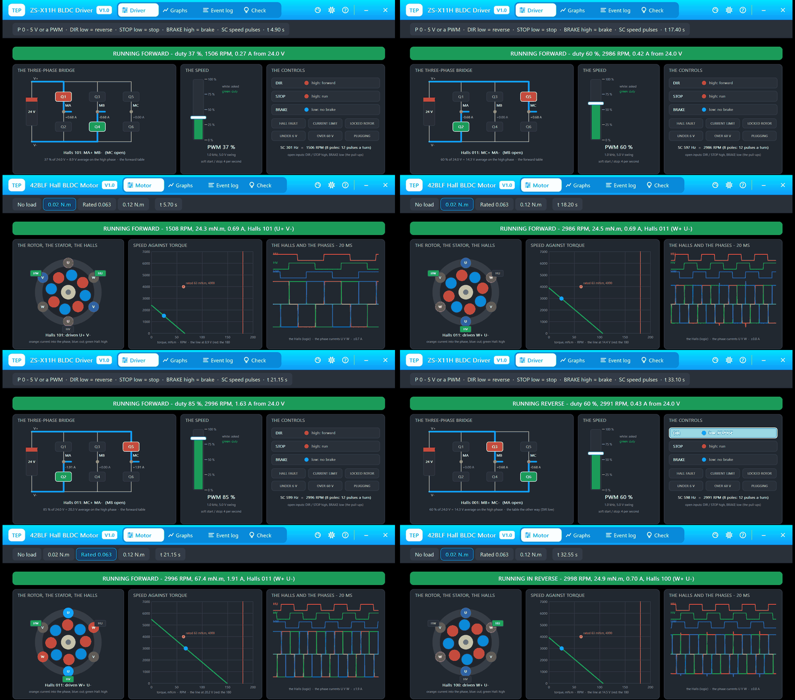
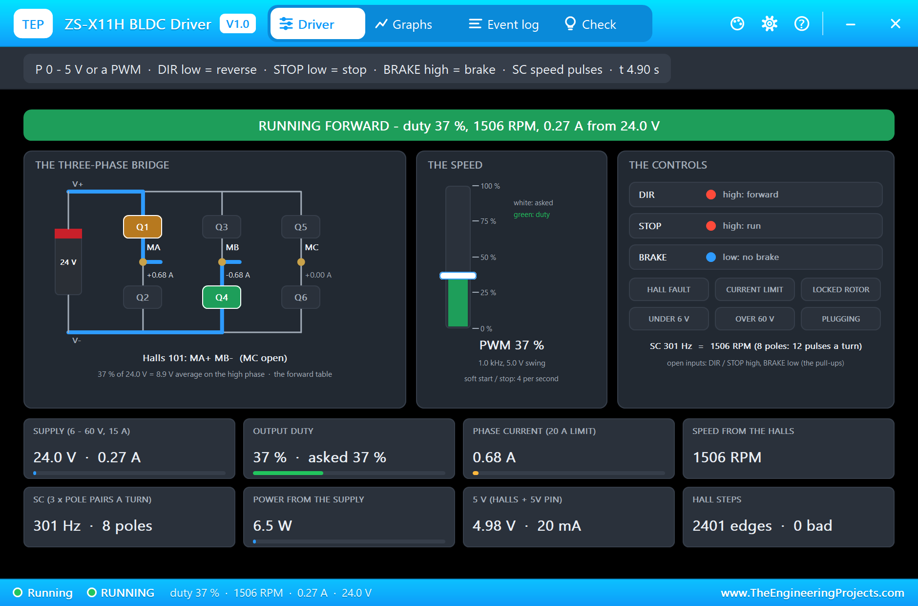
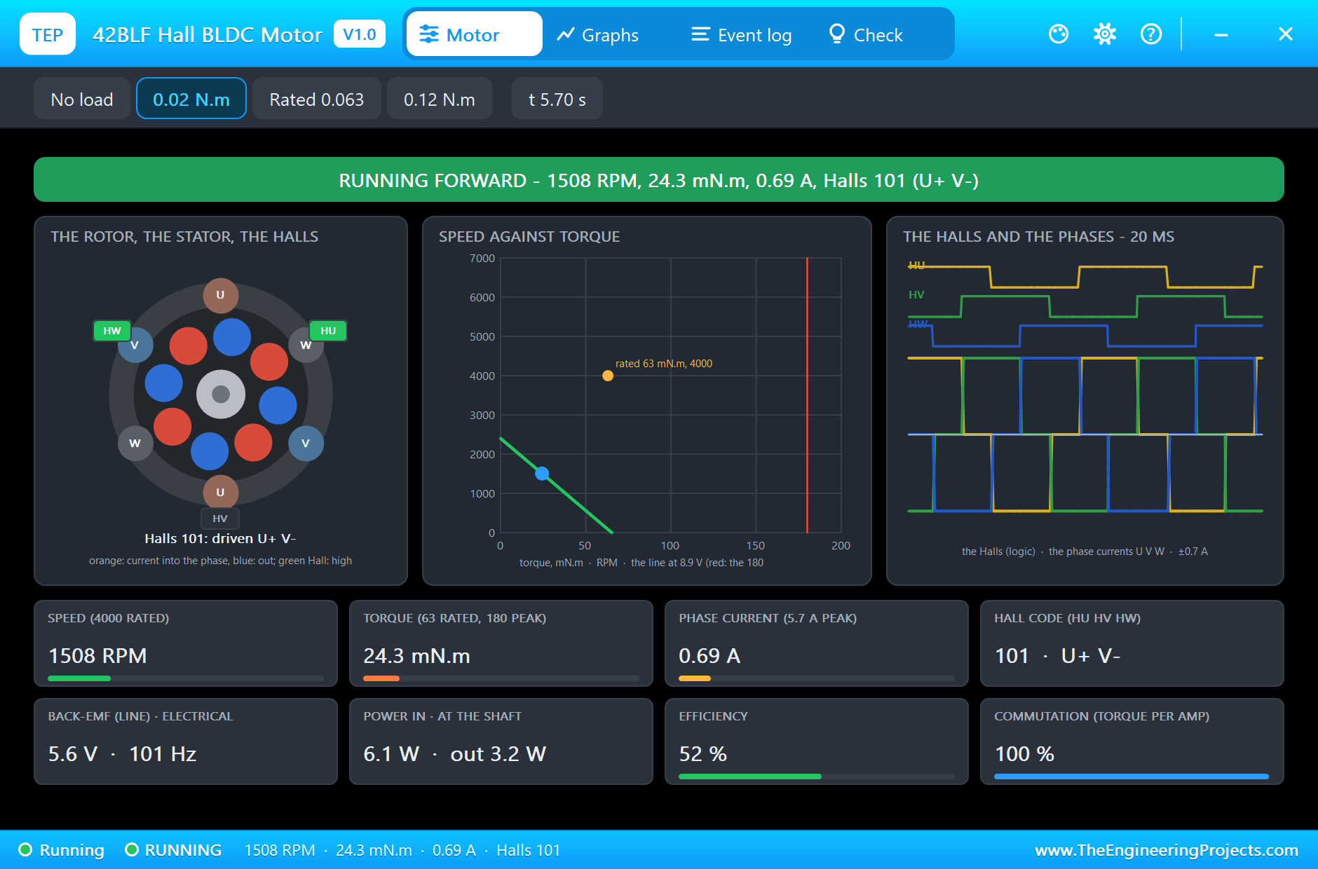
It is a great project for learning how brushless motors are driven, how to measure speed from pulses, and above all how closed-loop control works, the same idea behind cruise control, a drone's motors and a 3D printer's heaters. In the simulation, the ZS-X11H's pop-up shows its three-phase bridge switching, the duty and the controls, and the motor's pop-up shows the rotor turning, its Halls, the speed against the torque and the load picked from its chips.
Components Used in the Proteus Simulation
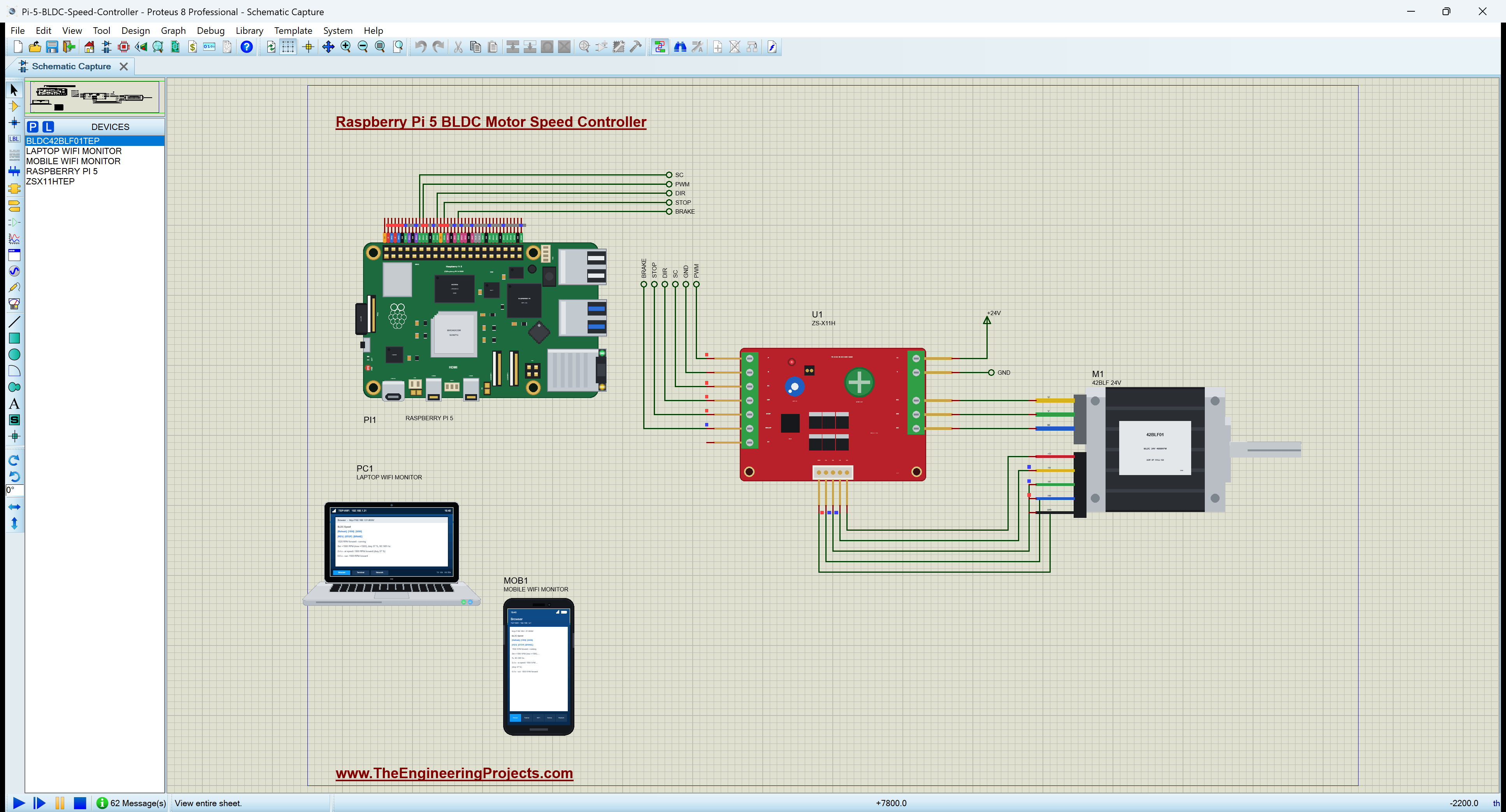
All the parts come from our Proteus libraries, each with its own tutorial. The project zip at the end includes every LIB and DLL file.
| Part | Proteus device | Library post | Connection |
|---|---|---|---|
| Raspberry Pi 5 | RASPBERRY PI 5 | Raspberry Pi 5 Library for Proteus | PI1, runs bldc_speed.py, 192.168.1.51 |
| ZS-X11H BLDC driver | ZSX11HTEP | ZS-X11H BLDC Driver Library for Proteus | U1, P / DIR / STOP / BRAKE / SC |
| 42BLF Hall BLDC motor | BLDC42BLF01TEP | 42BLF Hall BLDC Motor Library for Proteus | M1, U V W and the Hall cable |
| Laptop WiFi Monitor | LAPTOP WIFI MONITOR | Laptop WiFi Monitor | PC1 |
| Mobile WiFi Monitor | MOBILE WIFI MONITOR | Mobile WiFi Monitor | MOB1 |
The 24 V supply is a Proteus power terminal on the driver's V+. The driver and the motor are our models with pop-ups: the ZS-X11H solves its bridge together with the motor, and every Hall edge and control edge happens at its own time, so the speed, the currents and the commutation are worked out, not pretended.
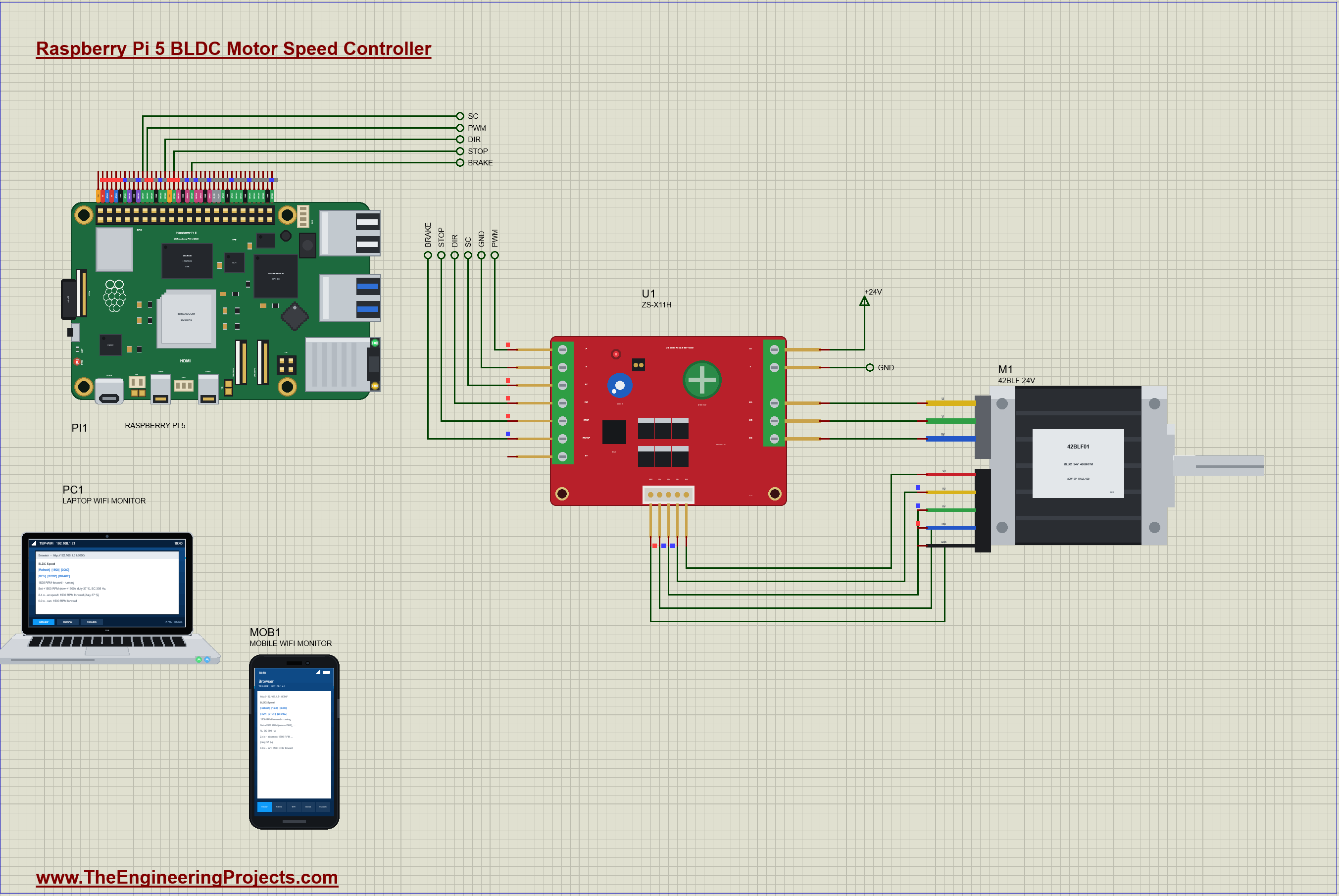
Proteus Simulation of the BLDC Controller: the Circuit
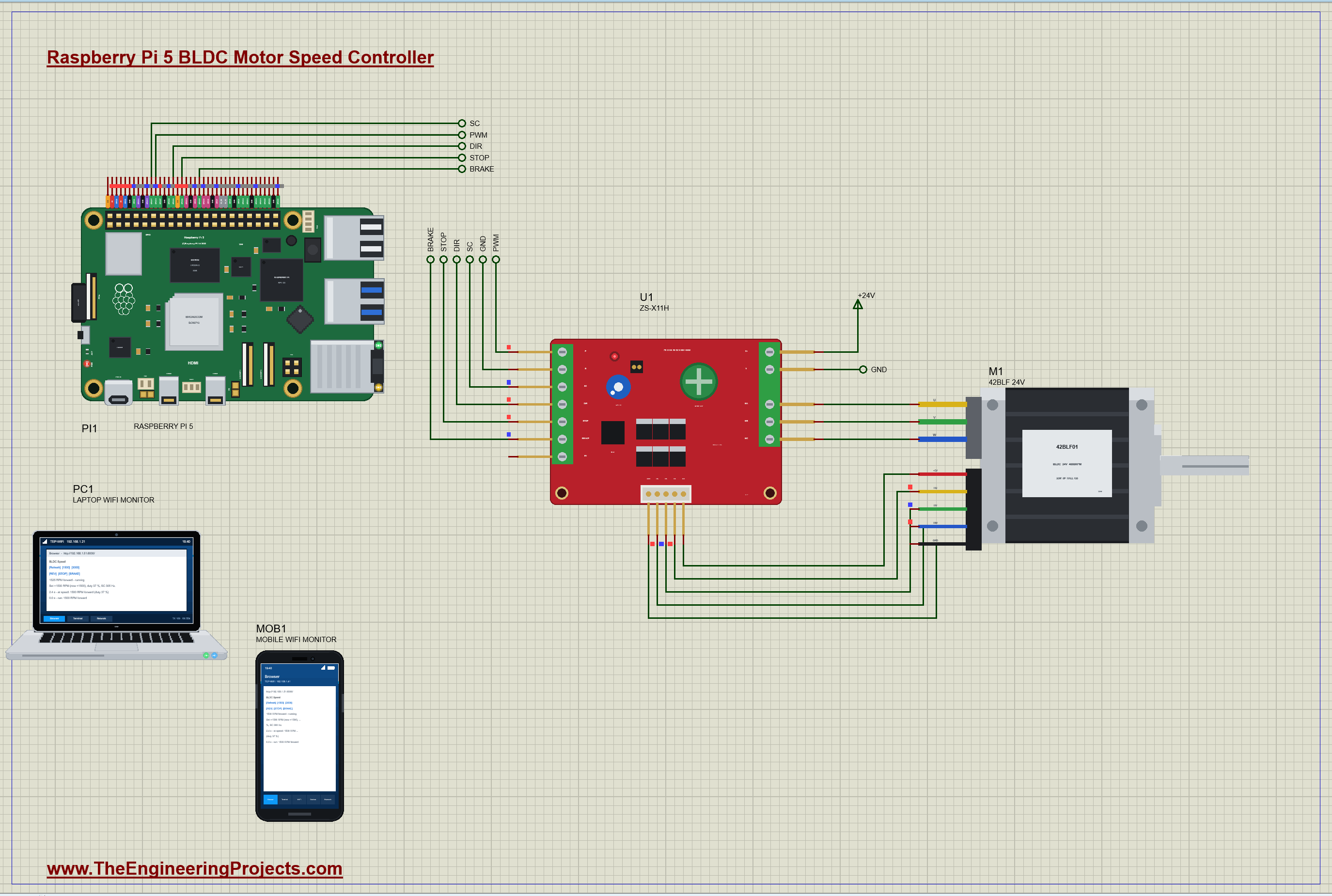
| ZS-X11H pin | Raspberry Pi 5 / other | What it does |
|---|---|---|
| P | GPIO18 (pin 12) | the speed command: a 1 kHz PWM |
| DIR | GPIO23 (pin 16) | HIGH forward, LOW reverse |
| STOP | GPIO24 (pin 18) | HIGH run, LOW stop (coast) |
| BRAKE | GPIO25 (pin 22) | HIGH brake (the windings shorted) |
| SC | GPIO17 (pin 11) | the speed pulses back, 12 a turn |
| V+ / V- | +24 V / GND | the motor's supply |
| MA MB MC, Ha Hb Hc | the motor's U V W and Halls | the phases and the Hall cable |
The Pi never touches the motor's current. It only sends logic signals to the driver and reads one back, which is how every motor controller is split: a small computer for the decisions and a power stage for the amps. On a real ZS-X11H the SC output is a 5 V signal, so it needs a 10k / 20k divider (or a level shifter) before the Pi's 3.3 V input; in the simulation the two models connect directly. The phases go straight across to the motor, and the motor's Hall cable comes back to the driver's Hall connector, which also powers the Hall sensors with 5 V.
How the BLDC Speed Controller Works
A Brushless Motor and Its Hall Sensors
A brushless DC motor turns the brushed motor inside out. The magnets are on the rotor and the windings are on the stator, in three phases, U, V and W, so no current has to reach the spinning part and nothing rubs. The price is that something outside must switch the windings in step with the rotor, pulling its magnets round, and to do that it must know where the rotor is. Three Hall sensors, 120 electrical degrees apart, give a 3-bit code that changes six times every electrical turn, each code saying which two phases to drive. Our 42BLF has 8 poles, 4 pole pairs, so one mechanical turn is four electrical turns: 24 Hall steps a turn, every one counted by the driver's pop-up.
What the ZS-X11H Does
The ZS-X11H is a three-phase bridge, six MOSFETs, with a controller that reads the Halls and switches them: for each Hall code one phase goes to the supply through a PWM switch, one goes to ground, and the third is left open. That is six-step, or 120 degree, commutation. The P input sets the PWM duty, and the duty sets the average voltage on the windings: 37 % of 24 V is 8.9 V, which is what the motor needs to turn at 1500 RPM with a light load, because at that speed its back-EMF, the voltage the spinning magnets make in the windings, almost balances it. The driver also handles DIR (the order of the steps), STOP (all switches off: the motor coasts), BRAKE (the three low switches on: the windings shorted) and a soft start, a current limit and a locked-rotor cut.
Measuring the Speed from SC
SC toggles at every Hall edge, which makes 3 x the pole pairs, 12 pulses a turn on our motor. The Pi counts the rising edges with an lgpio callback that just keeps a tally, and every 0.2 s it works out the speed: RPM = pulses / 0.2 s x 60 / 12. Worked example: at 3000 RPM the motor makes 50 turns a second, 600 pulses a second, 120 in each 0.2 s window. One pulse more or less is 25 RPM, which is why the readings step by 25 RPM, 2975, 3000, 3025: that is the resolution of counting for 0.2 s. A longer window would be finer but slower to react; for a motor with a flywheel, five readings a second at 25 RPM is a good balance.
Feed-forward and a PI Loop
The controller works out the duty in two parts. The feed-forward is what the speed needs with no load: from two runs, 37 % at 1500 RPM and 60 % at 3000 RPM, a straight line gives 14 % + 0.0153 % per RPM. Worked example: for 3000 RPM, 14 + 0.0153 x 3000 = 59.9 %. With the feed-forward alone the motor would reach about the right speed on its own, quickly and without overshoot, but any load would slow it. The PI loop corrects what is left. Its P part reacts to the error now, 0.005 % of duty for each RPM too slow; its I part adds up the error over time, 0.06 % per RPM-second, so a load that needs 25 % more duty is soon carried entirely by the integral and the error goes back to zero. That is the point of the I: a P loop alone always leaves a little error under load, because it needs the error to make the extra duty.
Two details make the loop behave in the real world. The set speed is ramped, at most 1500 RPM a second, so a jump from 1500 to 3000 RPM becomes a one-second climb that the motor can follow without hitting the driver's current limit. And the integral stops growing while the duty is at its limit, 0 or 95 %: otherwise, during a long acceleration it would pile up a huge correction and the motor would overshoot far past the set speed when it got there. This is called anti-windup, and you will find it in every serious PI or PID controller, including the one in our Raspberry Pi 5 PID Temperature Control.
Reversing Through Zero, Braking and Stalls
Flipping DIR on a motor at full speed is called plugging: the driver suddenly pushes against the spinning rotor, and the back-EMF adds to the supply instead of opposing it, so the current shoots up, the driver's current limit cuts in, and the mechanics take a hammer blow. Our controller never does it. REV sets a negative speed, the ramp brings the set speed down to zero, DIR changes only when the motor is below 100 RPM, and then the ramp takes it up the other way. BRAKE is different: it turns on the driver's three low-side switches, shorting the windings together, and the motor's own back-EMF drives a current through them that opposes the rotation, turning the motor's energy into heat in its windings. That stops it far faster than coasting with STOP. Finally, if the duty is above 30 % and the speed stays under 30 RPM for 1.5 s, something is jammed, and the program switches the motor off rather than cook it.
The Python Code Explained
The whole program is included in the download. It uses lgpio for the PWM, the outputs and the pulse counting, a thread for the control loop and http.server for the dashboard. At the top are the controller's numbers:
FF0, FF1 = 14.0, 0.0153                               # feed-forward: 14 % + 0.0153 % a RPM (37 % at 1500 RPM, 60 % at 3000, no load)
KP, KI = 0.005, 0.06                                  # PI: % duty per RPM of error, and per RPM-second
The PWM and the Speed Pulses
The PWM on P is timed by the Pi itself, at 1 kHz, within the ZS-X11H's 1 to 20 kHz; a callback with no function counts SC's rising edges:
lgpio.tx_pwm(chip, PWM_PIN, PWM_HZ if duty > 0 else 0, duty)sc = lgpio.callback(chip, SC_PIN, lgpio.RISING_EDGE) # (no function: it counts the edges) rpm = (n - last_n) / dt * 60 / PULSES_PER_TURNThe Ramp and the Reverse
A reverse sets the goal to zero first; DIR changes only once the ramp is at zero and the motor is nearly stopped:
goal = abs(target) if want == dirn else 0.0 # a reverse: down to zero first if want != dirn and cmd == 0 and rpm < 100: cmd = min(goal, cmd + step) if goal > cmd else max(goal, cmd - step)The Feed-forward and the PI Loop
ff = FF0 + FF1 * cmdThe integral grows only while the duty has room to move in the direction the error asks for; then the duty is the feed-forward plus the P and I parts, kept between 0 and 95 %:
                if 0 < duty < MAX_DUTY or (duty >= MAX_DUTY and err < 0) or (duty <= 0 and err > 0):
                    integ += KI * err * dt                   # (anti-windup: no integration while saturated)
                duty = max(0.0, min(MAX_DUTY, ff + KP * err + integ))
The Stall Guard and the Brake
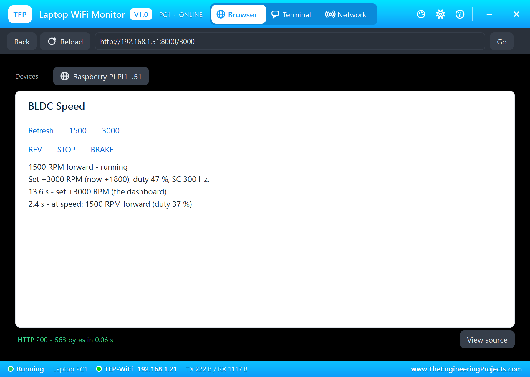
if duty > 30 and rpm < 30: lgpio.gpio_write(chip, BRAKE_PIN, 1 if brake else 0)The pages are / (the dashboard), /1500 and /3000 (the direction kept), /rev, /stop (a soft, ramped stop), /brake and /data (JSON). The dashboard puts its links first and stays short, because the WiFi Monitors show one screen of a page.
How to Run the Proteus Simulation
- Download the project zip below and install the library files and the TEPPi folder (the steps are under the download button).
- Open Pi-5-BLDC-Speed-Controller.pdsprj from the Proteus Simulation folder. Keep bldc_speed.py and the DLL files next to it.
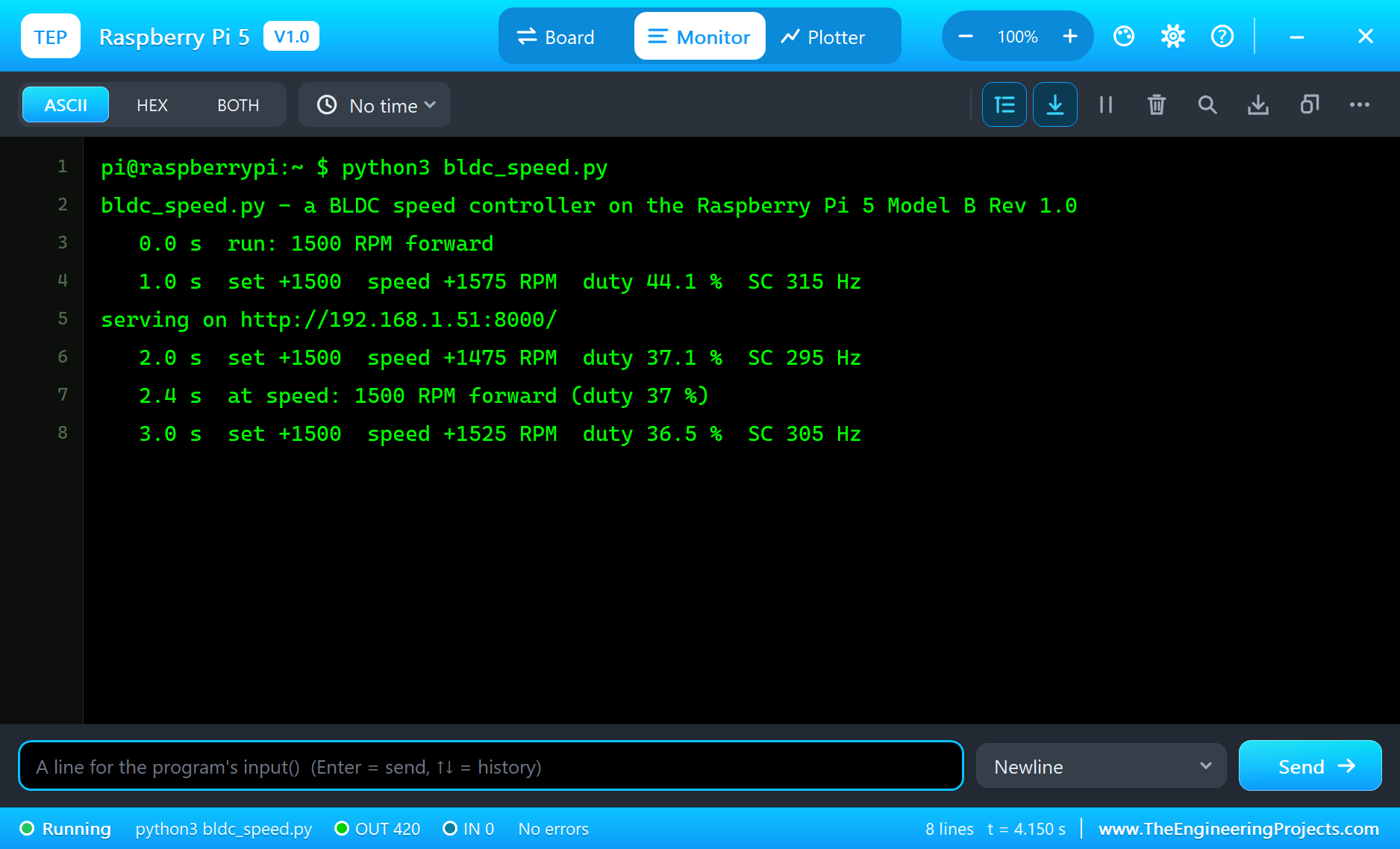
- Press Play. The motor ramps to 1500 RPM forward and the Pi's terminal prints a line every second.
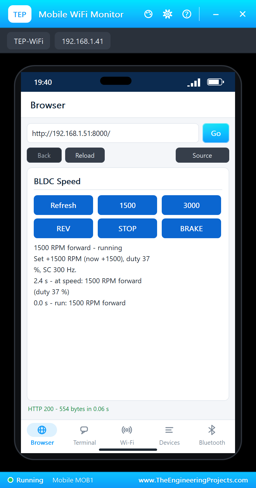
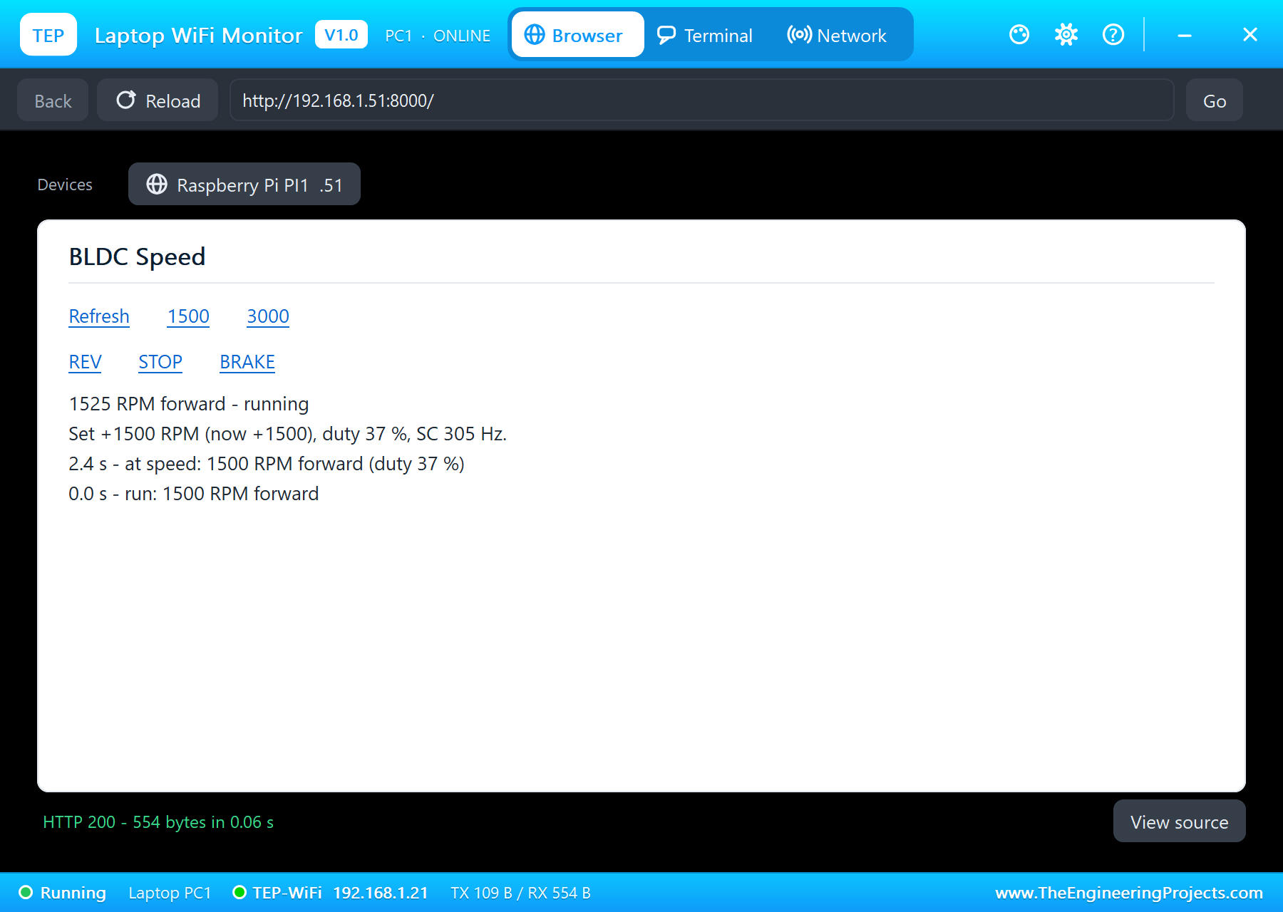
- Open the Laptop WiFi Monitor (PC1) or the Mobile WiFi Monitor (MOB1) and press Go: 1500, 3000, REV, STOP and BRAKE.
- Click the motor for its pop-up and pick a load with its chips, for example the rated 0.063 N.m: watch the duty rise.
Simulation Results: the BLDC Speed Controller in Proteus
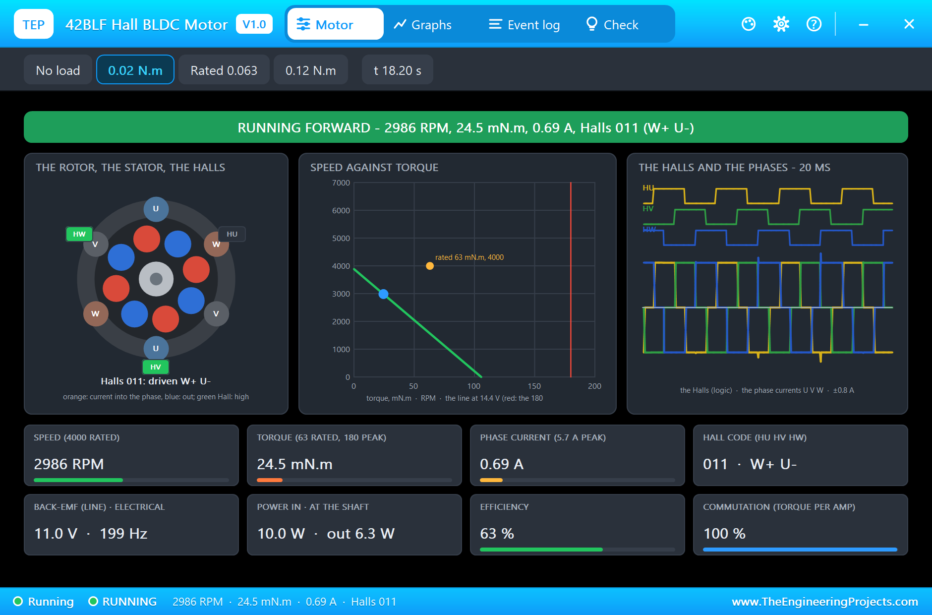
Here is the run that made the screenshots of this tutorial, 38.8 seconds of simulation. The times are the program's own, the seconds since it started, as it printed them in the Pi's terminal. The load was picked on the motor's pop-up: 0.02 N.m, a light load, at the start, the rated 0.063 N.m after the step to 3000 RPM, and 0.02 N.m again.
The Ramp to 1500 RPM
At 0.0 s the program starts the motor, "run: 1500 RPM forward". The ramp and the loop bring it to speed: at 2.4 s "at speed: 1500 RPM forward (duty 37 %)", exactly the feed-forward's 37 %, with SC at 300 Hz. From then on the speed reads 1475, 1500 or 1525 RPM, one pulse either side of the set speed. The driver's pop-up shows the bridge switching on the Halls, two phases conducting and one open, 37 % of 24 V on average and 0.27 A from the supply; the motor's pop-up shows 1508 RPM and 24.3 mN.m.
A Step to 3000 RPM
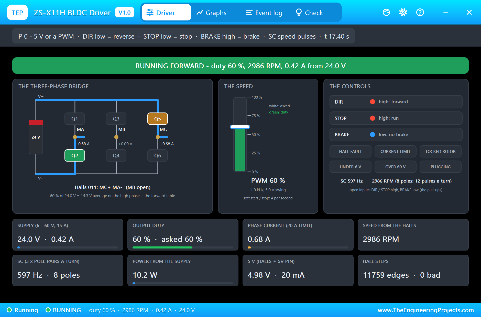
At 13.6 s 3000 on the laptop. The set speed climbs at 1500 RPM a second and the motor follows it; by 15.4 s "at speed: 2950 RPM forward (duty 60 %)", again just what the feed-forward predicts, and then 2975 to 3025 RPM with SC near 600 Hz. The driver now takes 0.42 A from 24 V, about 10 W, for a motor giving 6.3 W at the shaft against its light load.
The Rated Load: the Loop Holds the Speed
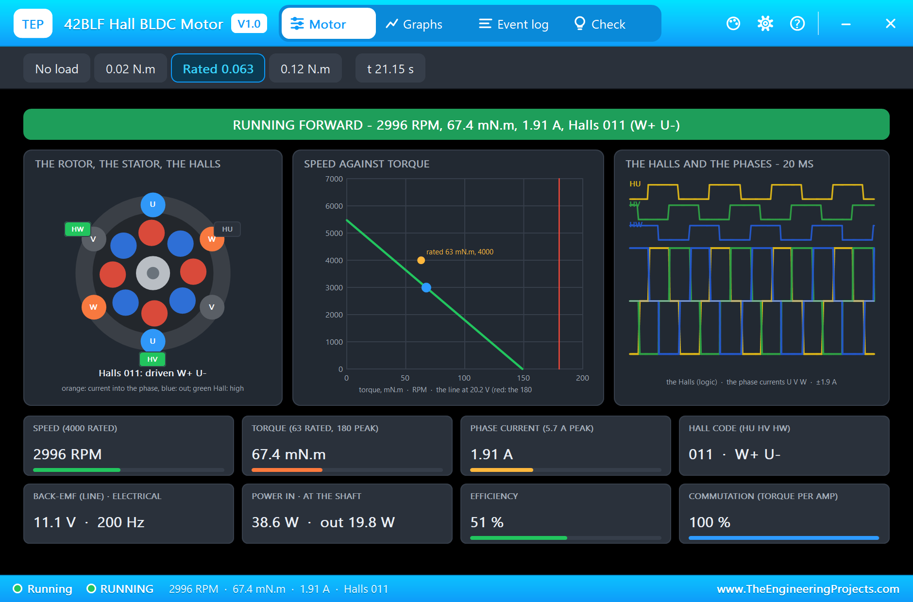
Then the rated load, 0.063 N.m, three times the light one, from the motor's pop-up. The speed drops at once: at 18.6 s "speed dip to 2725 RPM - a load: the loop raises the duty (65 %)", and at 19.0 s it is down to 2125 RPM. The PI loop answers: with 875 RPM of error, P adds 4.4 % and the integral climbs about 10 % in each 0.2 s step, and the duty reaches 91 %. The motor climbs back, and at 20.0 s "at speed: 2925 RPM forward (duty 85 %)"; after that it holds 3000 RPM at 84.5 %. The extra 25 points of duty are the integral's work: the feed-forward still asks for 60 %, and the error has gone back to zero. The motor's pop-up shows 67.4 mN.m and 1.91 A in its phases at 2996 RPM, its rated point; the driver takes 1.63 A, 39 W, from the supply.
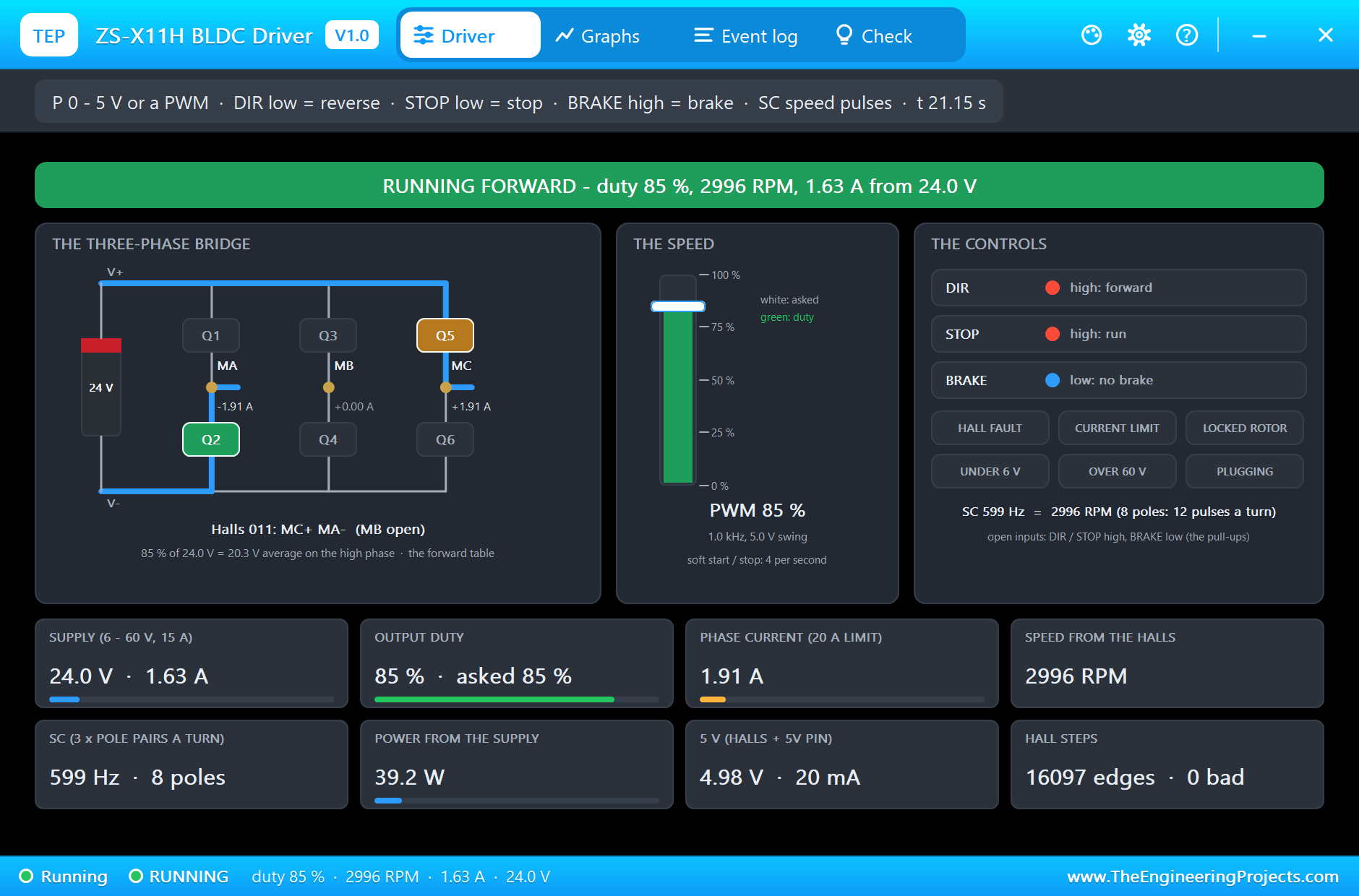
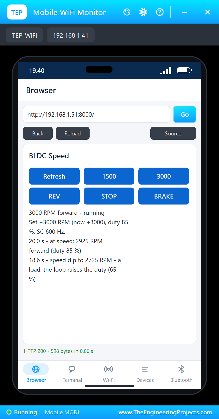
When the light load comes back, the speed jumps a little and the integral unwinds: by 24.0 s the duty is 57.8 % and at 25.0 s back to 60 % at 3000 RPM.
A Reverse Through Zero
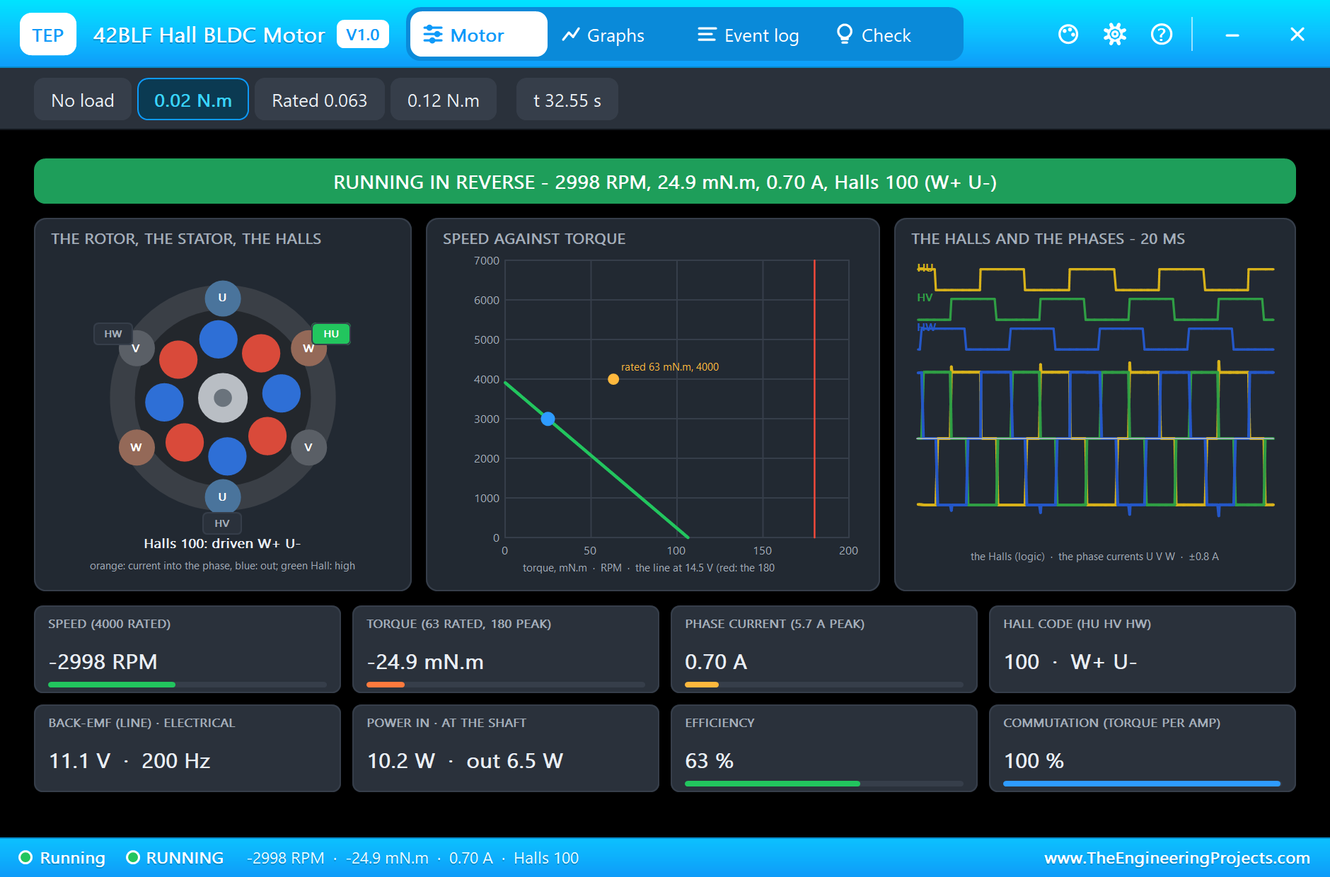
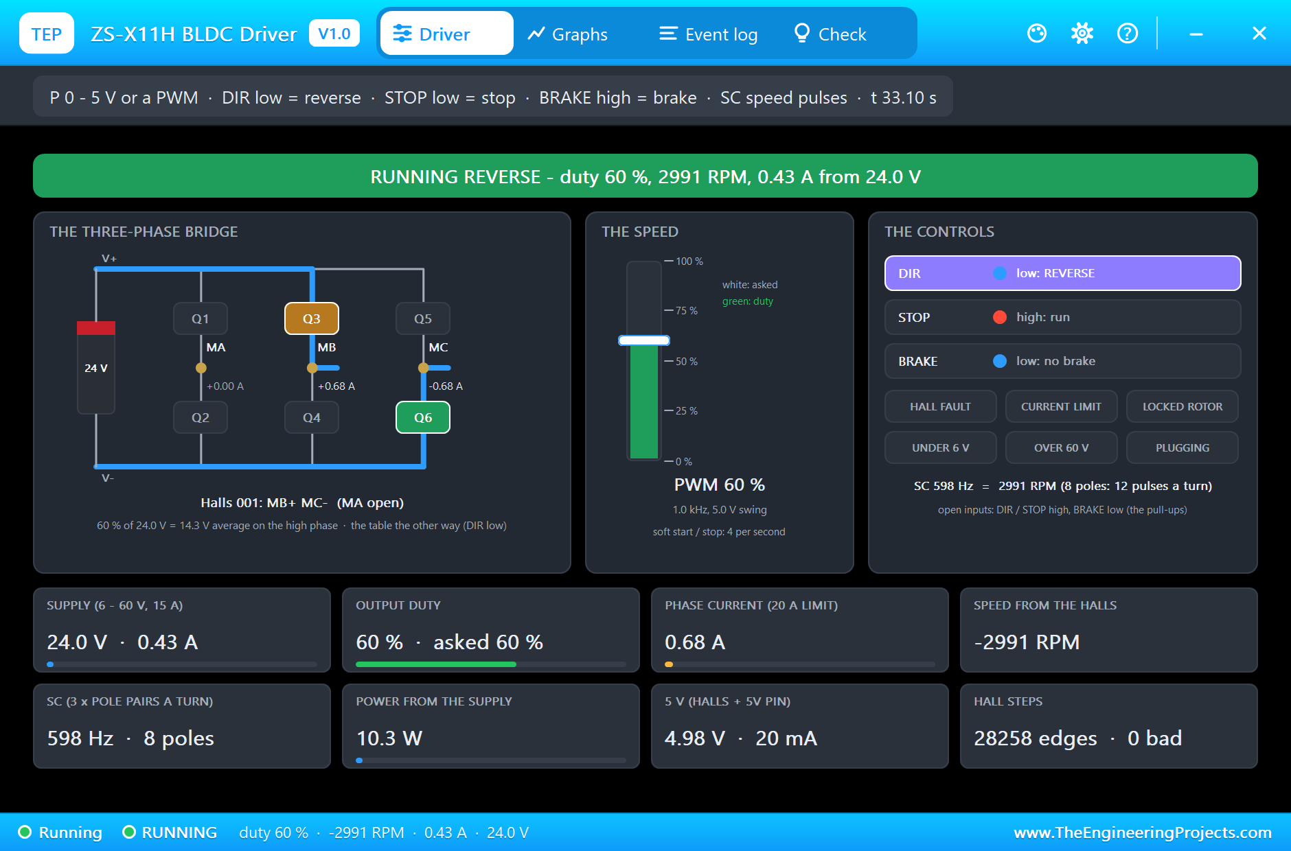
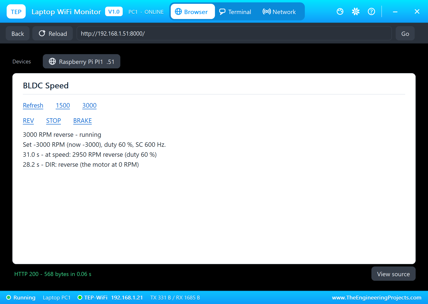
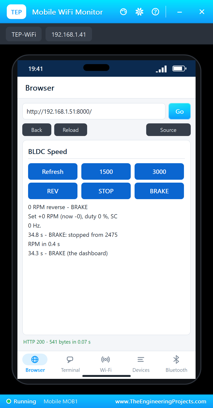
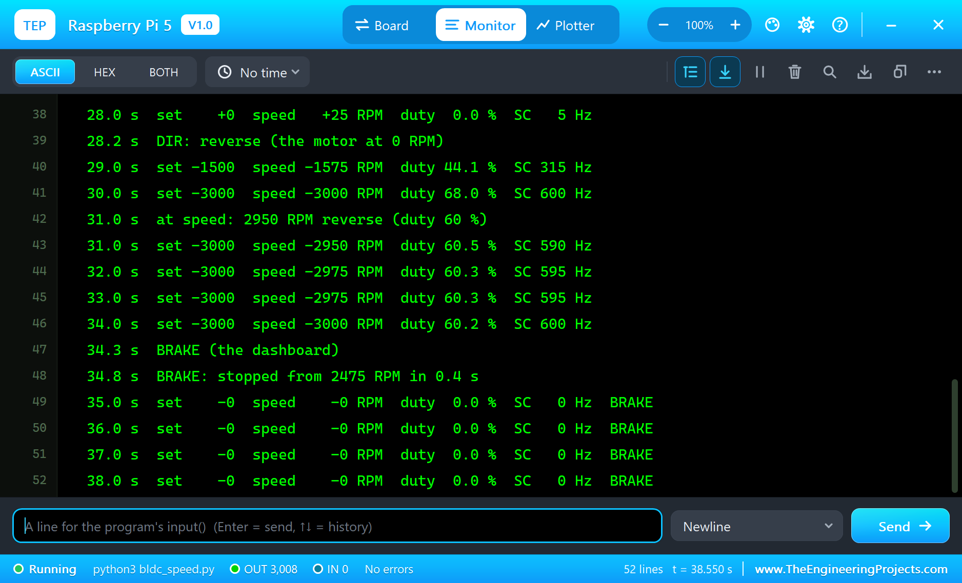
At 26.0 s REV on the phone: "set -3000 RPM". The motor does not reverse at once. The ramp takes the set speed down, 1450 RPM at 27.0 s, 25 RPM at 28.0 s, and at 28.2 s "DIR: reverse (the motor at 0 RPM)". Then it climbs the other way, and at 31.0 s "at speed: 2950 RPM reverse (duty 60 %)": the same duty in reverse, as it should be for the same speed and load. The motor's pop-up shows -2998 RPM, and the driver's shows DIR low and the steps in the reverse order.
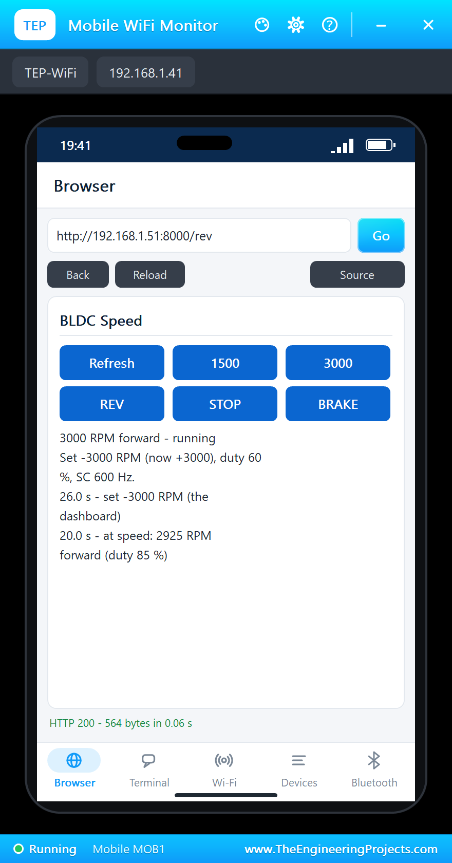
The Brake
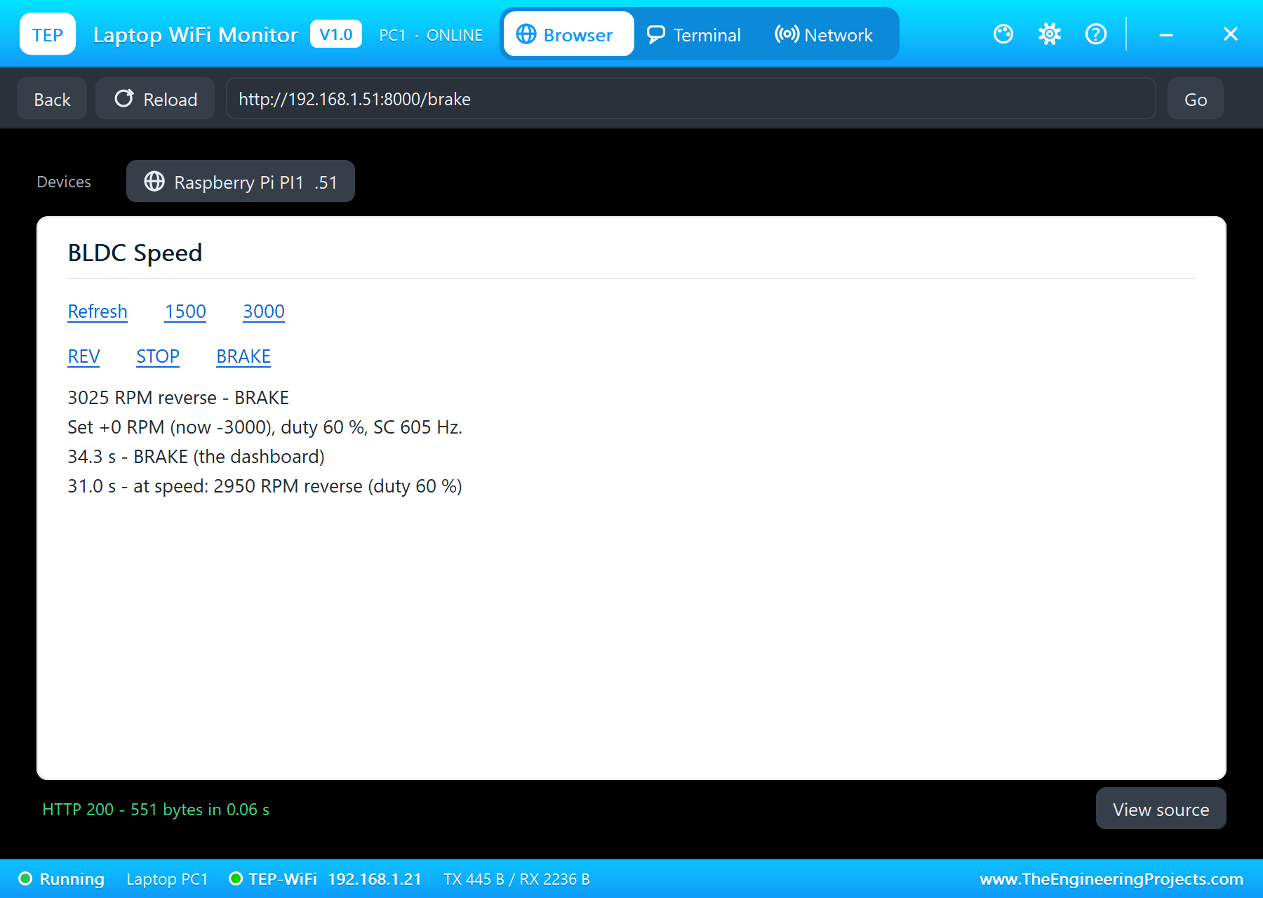
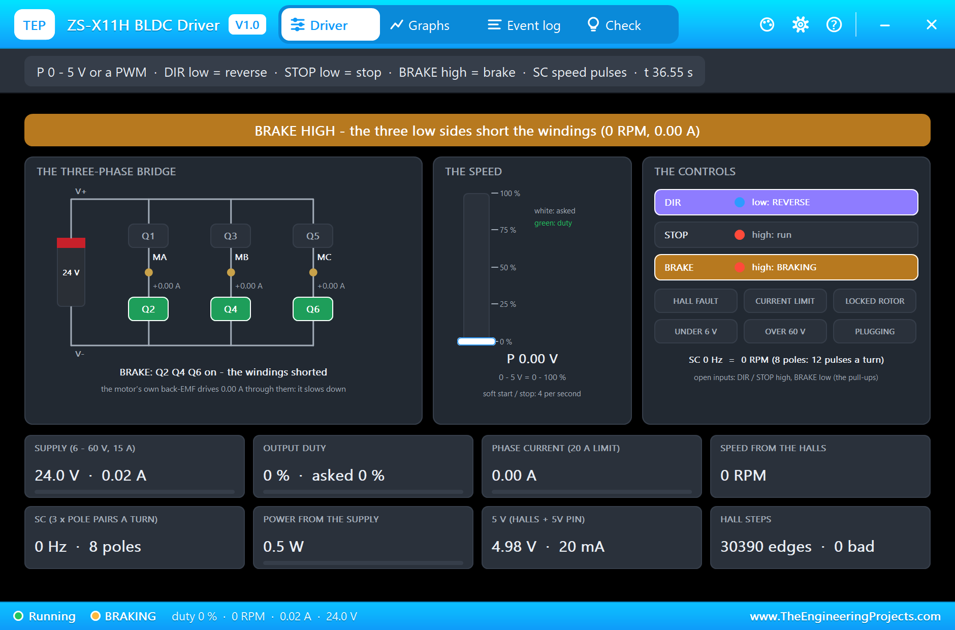
At 34.3 s BRAKE on the laptop. The PWM stops and BRAKE goes high: the driver turns on its three low-side switches and shorts the windings. The motor's back-EMF drives a braking current through them, and at 34.8 s "BRAKE: stopped from 2475 RPM in 0.4 s", flywheel and all. The driver's pop-up shows BRAKE HIGH, the three low switches on and 0 RPM. In the whole run the driver counted 30,390 Hall steps without a single bad one.
The Numbers of the Run
| What | Result |
|---|---|
| 1500 RPM | at speed at 2.4 s, duty 37 % |
| 3000 RPM | at speed at 15.4 s, duty 60 % (light load) |
| The rated load | dip to 2125 RPM, back at speed at 20.0 s, 3000 RPM at 84.5 % |
| Reverse | DIR at 0 RPM at 28.2 s, 3000 RPM reverse at 31.0 s |
| Brake | from 2475 RPM to 0 in 0.4 s |
| Commutation | 30,390 Hall steps, 0 bad |
| Simulation | 38.8 s of simulation |
Download the Project Files
Click the button below to download Raspberry-Pi-5-BLDC-Motor-Speed-Control-ZS-X11H-Proteus-Simulation-v1.0.zip (about 13.3 MB, without the source code of the models):
Closed-Loop BLDC Speed Control on Raspberry Pi 5 in Proteus Simulation V1.0- Proteus Simulation: Pi-5-BLDC-Speed-Controller.pdsprj, the program bldc_speed.py and copies of the models.
- Python Code: bldc_speed.py, the complete program.
- Proteus Library Files: the LIB files of the Raspberry Pi 5, the ZS-X11H, the 42BLF motor and the two WiFi Monitors.
- Proteus Model Files: the DLL models and the TEPPi folder, the Python 3.11 and the runtime that the Pi board runs.
- README.txt: the installation steps, the properties, the test results and the links to every library post.
No Proteus yet? Read How to Download and Install Proteus 7 and 8. New to libraries? Follow How to Install a New Library in Proteus.
How to Install the Project Files
- Close Proteus and extract the whole zip file, for example to your Desktop.
- Copy the files from Proteus Library Files into the LIBRARY folder of Proteus.
- Copy everything in Proteus Model Files, the DLL files and the TEPPi folder, into the MODELS folder.
- Start Proteus and open the project from the Proteus Simulation folder.
Changing the Code
The program is plain Python 3: edit bldc_speed.py beside the project and press Play again; the Pi board runs the new file. The feed-forward, the PI gains, the ramp and the speeds are at the top. The same program runs on a real Raspberry Pi 5 with Raspberry Pi OS and lgpio.
Ideas to Extend the Project
- Add a speed slider to the dashboard instead of two fixed speeds.
- Read the motor current with an INA219 and limit the torque as well as the speed.
- Log the speed and the duty and draw them as a live graph.
- Tune the loop automatically: step the speed and measure how the motor answers.
- Hold a position instead of a speed by counting the Hall steps.
- Drive several motors, each with its own driver and loop, from one Pi.
From Simulation to Real Hardware
- Level-shift SC: the ZS-X11H's SC is a 5 V signal; a 10k / 20k divider brings it to 3.3 V for the Pi.
- Drive the control inputs safely: on the board DIR and STOP are pulled up to 5 V and BRAKE down; a transistor or a 74HCT buffer between them and the Pi makes the levels certain.
- Size the supply: the motor took 1.6 A from 24 V at its rated load; give it a supply with headroom and a fuse.
- Keep the grounds together: the Pi's ground and the driver's logic ground must be joined, close to the driver.
- Mind the Hall cable: swapped Halls make a motor shudder or run rough; the driver's fault outputs and a scope show it quickly.
Troubleshooting
- The motor does not turn: no 24 V on V+, STOP low, or the Hall cable swapped (the driver's pop-up counts bad steps).
- The speed reads 0 while the motor turns: SC is not reaching GPIO17.
- The speed overshoots or hunts: lower KP and KI at the top of the program.
- The stall guard stops it at the start: the motor is jammed or its load is too heavy for the duty limit.
- The terminal cannot start Python: the TEPPi folder is not in MODELS.
Limitations of the Simulation
- The load is a torque set from the motor's pop-up; a real load changes with the speed, a fan's for example with its square.
- The bridge is averaged over each PWM period rather than switched at 1 kHz edge by edge, which is what lets the simulation run fast.
- In the simulation SC connects straight to the Pi's pin; a real board needs the level shifting described above.
- The network is simulated: the dashboard travels between the Pi and the two monitors inside Proteus; the times in this tutorial are simulation time.
- Raspberry Pi is a trademark of Raspberry Pi Ltd. This project is not made or endorsed by them, by the makers of the ZS-X11H and the 42BLF motor, or by Labcenter.
So, that was all about the Closed-Loop BLDC Speed Control on Raspberry Pi 5 (Proteus Simulation). I hope it helps you understand how a brushless motor is controlled: Hall sensors and a three-phase bridge for the commutation, pulses counted for the speed, a feed-forward for the speed and a PI loop for the load, a ramp, a reverse through zero and a brake, all tested in a simulation before you connect a single real motor. More IoT projects with the ESP32 and the Raspberry Pi 5 are coming in this series. If you have any questions, ask in the comments and I will help you out. Till the next tutorial, take care and have fun!