Hello friends, I hope you all are doing great. Today, I am going to share the Raspberry Pi 5 Gas Leak and Fire Alarm - Proteus Simulation, the sixth project of our IoT Projects series. If you have searched for a Proteus simulation of a gas leak detector or a fire alarm with a Raspberry Pi, here is a complete one. A Raspberry Pi 5 watches a kitchen or a workshop with an MQ-2 gas sensor and a flame sensor, sounds a buzzer, runs an exhaust fan to clear the gas, and shows everything on a live web dashboard for your laptop and your phone.
Gas leaks and fires are the two dangers every home and workshop alarm watches for, and they make a great IoT project because they bring together analog sensors, a converter, power electronics and a web page. In this tutorial, we will go through the circuit, see why a Raspberry Pi 5 needs an ADS1115 to read analog sensors, learn how an MQ-2 turns gas into a resistance and how the program turns that into parts per million, walk through the Python code, and then run the simulation through a gas leak, a fire and a blocked fan. At the end, you can download the project with the program, every library file and the Python runtime the Pi needs.
NOTICE: Our team has put a lot of effort into this project: the circuit, the code and every part in the simulation are our own work, and you get them all free. Your feedback is the fuel that keeps us going, so please tell us what you think in the comments below. And if our free projects help you, you can buy us a coffee. So, let's get started with the Raspberry Pi 5 Gas Leak and Fire Alarm - Proteus Simulation:
What Does This Gas and Fire Alarm Do?
The alarm watches for two different dangers and reacts to each in the right way, the way a real safety system does.
- Gas: an MQ-2 sensor measures flammable gas such as LPG; the program turns its output into parts per million (ppm).
- Flame: a flame sensor sees the infrared light of a flame and gives a digital alarm and an analog strength.
- Three levels: GAS WARNING from 500 ppm, GAS ALARM from 2000 ppm, and FIRE for a flame.
- An exhaust fan: a 4-pin PC fan runs at full speed to clear gas, and slows down in a fire, because air feeds a fire.
- A buzzer and LEDs: a beeping buzzer for gas, a steady one for fire; a green LED for all clear and a red one for alarms.
- A fan check: the fan's tach signal proves it is really turning; a stopped fan is reported on the page.
- A dashboard: the state, the gas, the flame, the fan and an event log, with SILENCE, PURGE FAN and TEST buttons.
It is a good project for anyone learning the Raspberry Pi, analog sensors or IoT dashboards, and a strong final-year or school project on home safety. In the simulation, you can start a gas leak or light a candle at the click of a button, which is much safer than testing a real alarm with a real gas.
Components Used in the Proteus Simulation
All the parts come from our Proteus libraries, each with its own tutorial. The project zip at the end includes every LIB and DLL file.
| Part | Proteus device | Library post | Connection |
|---|---|---|---|
| Raspberry Pi 5 | RASPBERRY PI 5 | Raspberry Pi 5 Library for Proteus | PI1, Ethernet 192.168.1.51 |
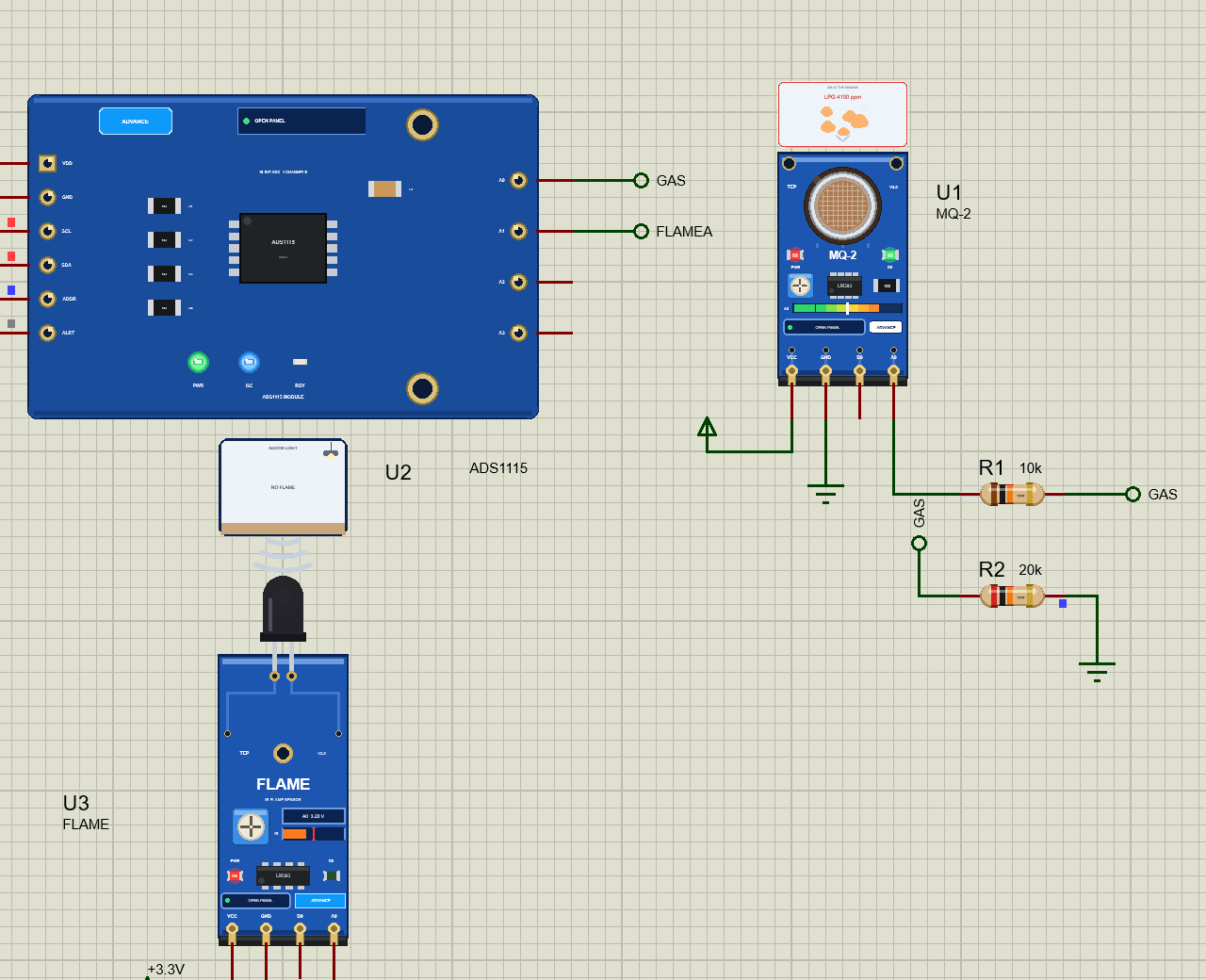
| MQ-2 gas sensor | MQ2ADVTEP | Gas Sensor MQ-2 Library for Proteus | U1, 5 V, A0 through 10k / 20k to the ADS1115 |
| ADS1115 16-bit ADC | ADS1115ADVTEP | ADS1115 ADC Library for Proteus | U2, 3.3 V, I2C 0x48 |
| Flame sensor | FLAMEADVTEP | Flame Sensor Library for Proteus | U3, 3.3 V, A0 to the ADS1115 |
| 4-pin PC fan | PCFAN4PINTEP | 4-Pin PC Fan Library for Proteus | FAN1, 12 V, PWM GPIO18, TACH GPIO23 |
| Active buzzer | BUZZERACTIVETEP | Active Buzzer Library for Proteus | BZ1, 5 V, through Q1 |
| BC547B transistor | BC547BTEP | Small Transistors Library | Q1, base from GPIO27 through 1k (R4), 1k across the buzzer (R3) |
| LEDs and resistors | LED5MMGREENTEP, RESISTOR4BANDTEP | 5mm LED Library, Resistor Library | GPIO24 green, GPIO22 red |
| Laptop WiFi Monitor | LAPTOP WIFI MONITOR | Laptop WiFi Monitor | PC1 |
| Mobile WiFi Monitor | MOBILE WIFI MONITOR | Mobile WiFi Monitor | MOB1 |
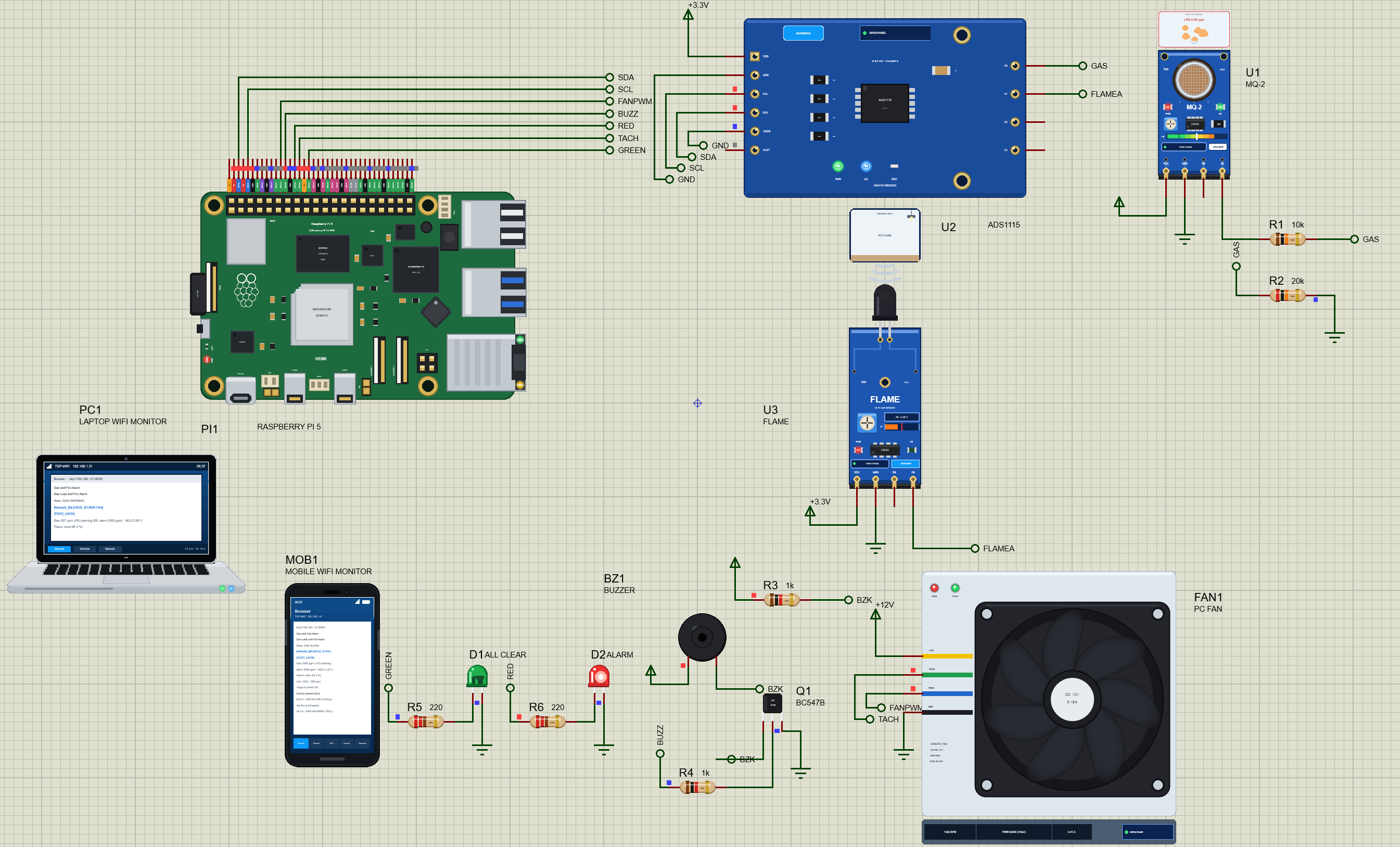
The MQ-2, the flame sensor and the ADS1115 are Advance models with pop-ups. The MQ-2's pop-up holds the room: CLEAN AIR, LPG LEAK, SMOKE and other gases, the concentration and VENTILATE. The flame sensor's pop-up holds the flame: NONE, CANDLE, LIGHTER or GAS BURNER, the distance and the ambient light. The fan's pop-up shows its speed and lets you block the rotor.
Proteus Simulation of the Gas and Fire Alarm: the Circuit
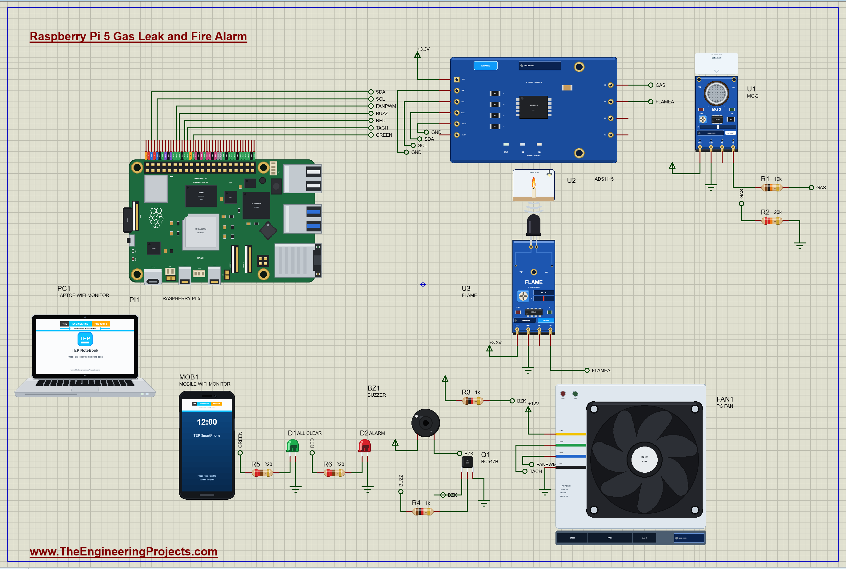
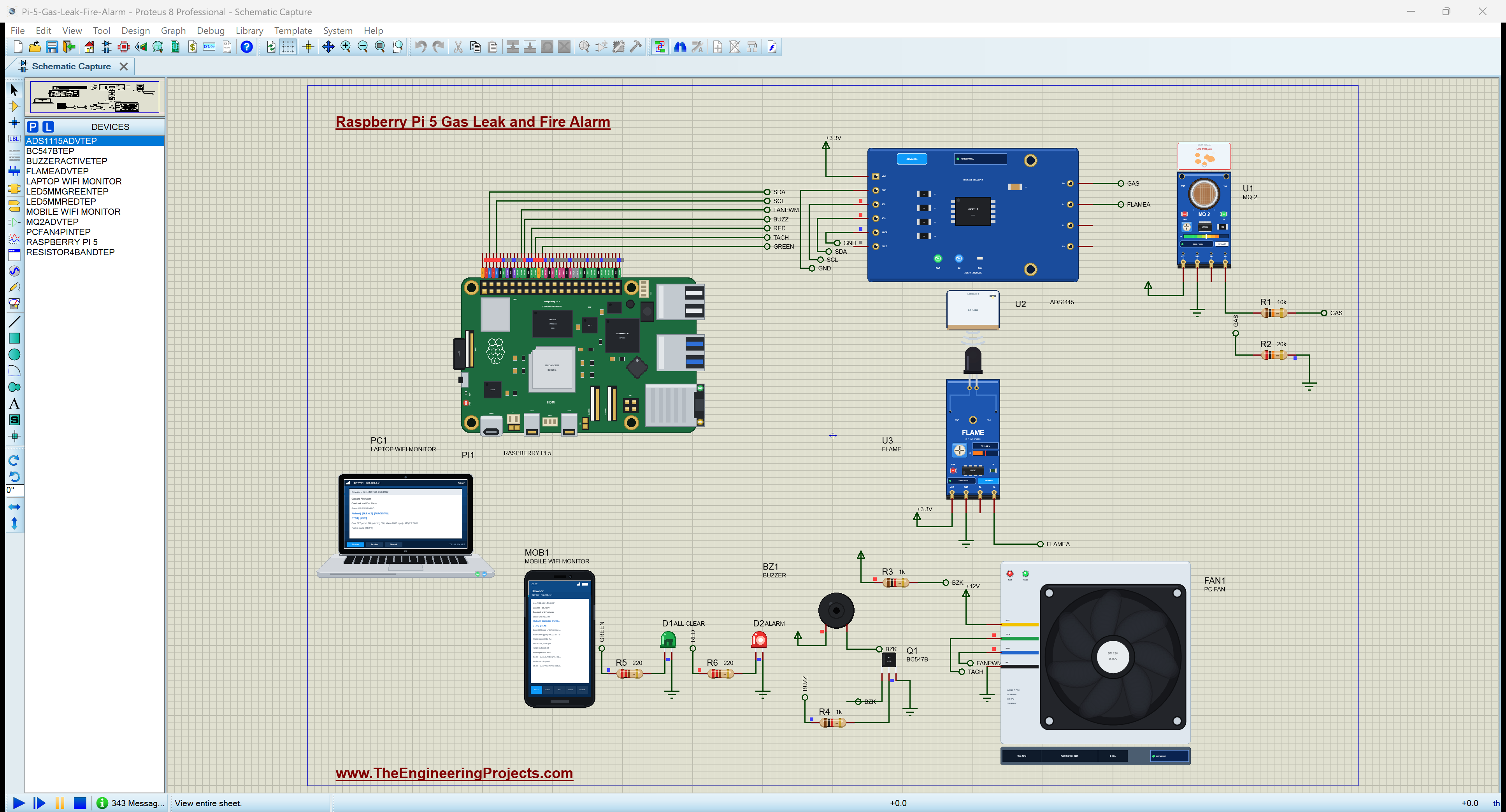
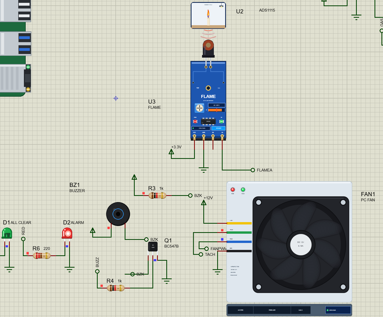
Every signal leaves the Pi's header through a net label, so the sheet stays easy to read. These are the connections:
| Pi 5 pin | GPIO | Goes to |
|---|---|---|
| 3 / 5 | GPIO2 / GPIO3 | SDA / SCL of the ADS1115 (I2C1) |
| 12 | GPIO18 | the fan's PWM wire |
| 13 | GPIO27 | the buzzer transistor's base, through 1k |
| 15 | GPIO22 | the red LED, through 220 ohm |
| 16 | GPIO23 | the fan's TACH, held high by the Pi's own pull-up |
| 18 | GPIO24 | the green LED, through 220 ohm |
Why an ADS1115?
The Raspberry Pi 5 has no analog inputs at all: its GPIOs only know HIGH and LOW. Both of our sensors give an analog voltage, so the Pi needs an analog-to-digital converter. The ADS1115 is a favourite: four inputs, 16 bits, a programmable gain and an I2C interface. On the +-4.096 V range, one step is 125 microvolts, far finer than the sensors need. With its ADDR pin on ground, it answers at address 0x48.
A 5 V Sensor and a 3.3 V Converter
The MQ-2's heater needs 5 V, and its analog output can rise almost to 5 V. The ADS1115 runs on 3.3 V here, the same as the Pi's I2C bus, and its inputs must stay below its supply. So the MQ-2's output goes through a divider: 10k on top (R1) and 20k below (R2). The ADS1115 sees two thirds of the voltage, and 5 V becomes 3.33 V. The program multiplies back by 1.5. The flame sensor runs on 3.3 V, so its analog output goes straight to the ADS1115's second input.
The Buzzer and the Fan
The active buzzer runs on 5 V and draws close to 30 mA, more than a Pi GPIO should give. A BC547B transistor switches it on its low side: GPIO27 drives the base through 1k (R4), and the transistor connects the buzzer to ground. One more resistor, R3 (1k), sits across the buzzer. An active buzzer draws almost nothing until it has about 2 V, so without R3 the transistor's collector would float while the buzzer is silent; with it, the collector rests at 5 V and the transistor switches cleanly.
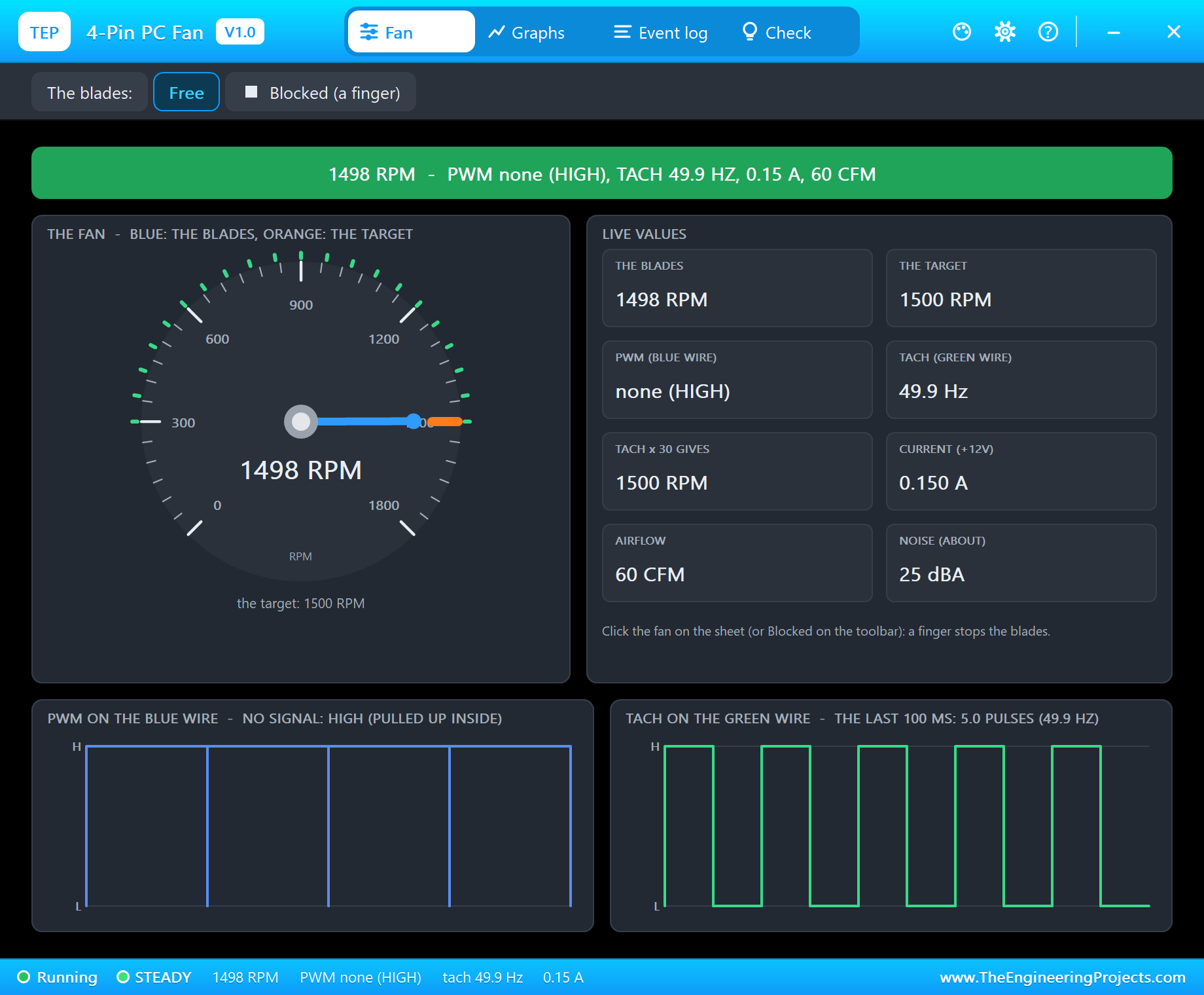
The fan runs on 12 V. Its PWM wire sets the speed: held LOW, the fan turns at its minimum, 300 rpm; HIGH, at full speed, 1,500 rpm. Its TACH wire is an open collector that pulls low twice a turn and needs a pull-up. The program turns on the Pi's own pull-up resistor on GPIO23, so the tach swings between 0 and 3.3 V. Never pull a tach up to 12 V: that would damage the Pi.
In the simulation, the supplies come from power terminals: 5 V for the MQ-2 and the buzzer, 3.3 V for the ADS1115 and the flame sensor, 12 V for the fan. On a real build, these are the Pi's own 5 V and 3.3 V pins and a 12 V adapter with its ground joined to the Pi's.
How the Gas and Fire Alarm Works
How an MQ-2 Senses Gas
Inside an MQ-2 is a small tube of tin dioxide with a heater. In clean air, oxygen sits on the hot tin dioxide and its resistance, Rs, is high. Flammable gases react with that oxygen, and Rs falls: the more gas, the lower Rs. The module puts Rs in series with a load resistor, RL (1 kohm), across 5 V, so its output rises with the gas. The heater needs time to reach its temperature, which is why the sensor reads high just after power-up and the program waits 20 seconds before it trusts it.
From Volts to ppm
The datasheet gives the gas as a curve of Rs / R0, where R0 is the sensor's resistance in clean air, a little different for every sensor. So the program first calibrates: after the warm-up, it measures Rs in clean air and divides by 9.83, the clean-air ratio from the datasheet, to get R0. After that, each reading becomes a ratio, and the LPG curve, ppm = 574.25 x (Rs / R0) ^ -2.222, turns the ratio into parts per million. The same method works for smoke, hydrogen or methane with their own curves.
How the Flame Sensor Works
A flame gives off infrared light around 760 to 1100 nm. The flame sensor has an infrared photodiode that conducts more as more of that light falls on it; its analog output falls as the infrared rises. The module also has an LM393 comparator that pulls its D0 pin LOW when the output passes a pot's setting, but the comparator has no hysteresis, so a flickering flame can make D0 chatter. This project reads the analog output instead and does the comparison in the program: the infrared strength, from 0 to 100 %, must reach 50 % for a flame, and fall below 35 % before the flame counts as gone. That gap is hysteresis, and three readings in a row are needed either way.
The Alarm Levels
| State | When | Buzzer | Red LED | Fan |
|---|---|---|---|---|
| ALL CLEAR | under 500 ppm, no flame | off | off (green on) | slow |
| GAS WARNING | 500 ppm or more | off | blinking | full speed |
| GAS ALARM | 2000 ppm or more | beeping | on | full speed |
| FIRE | a flame | steady | on | slow |
Why 2000 ppm? LPG burns between 2.1 % and 9.5 % in air; 2.1 %, or 21,000 ppm, is its lower explosive limit (LEL). Gas detectors usually alarm at 10 to 20 % of the LEL, long before the air can burn, so 2000 ppm is about 10 % of LPG's LEL.
The Python Code Explained
The whole program is included in the download. It uses only lgpio, which the Raspberry Pi 5 needs for its GPIOs, and the standard library's http.server. At the top are the pins, the sensor constants and the alarm levels:
WARMUP_S = 20                      # the MQ-2's heater warms up for this long before the calibration
RL = 1.0                           # kohm: the MQ-2 module's load resistor
CLEAN_AIR = 9.83                   # Rs / R0 of an MQ-2 in clean air (from its datasheet curve)
LPG_A, LPG_B = 574.25, -2.222      # the MQ-2's LPG curve: ppm = A x (Rs / R0) ^ B
DIVIDER = 1.5                      # 10k over 20k: the ADC sees 2/3 of the MQ-2's output
WARN_PPM, ALARM_PPM = 500, 2000    # 2000 ppm of LPG is about 10 % of its lower explosive limit (2.1 % = 21,000 ppm)
Reading the ADS1115
The ADS1115 has a configuration register and a result register. One 16-bit word in the configuration register starts a single conversion and chooses the input, the range and the speed; the program then waits until the OS bit says the conversion is done and reads the result, a signed 16-bit number:
    def volts(self, ch):
        cfg = 0x8000 | (4 + ch) << 12 | 0x0200 | 0x0100 | 0x0080 | 0x0003
        # OS 1 = start | MUX 1xx = AINx against GND | PGA 001 = +-4.096 V | MODE 1 = single shot | DR 100 = 128 SPS | COMP_QUE 11 = off
        lgpio.i2c_write_i2c_block_data(self.h, 1, [cfg >> 8, cfg & 0xFF])
From the MQ-2's Voltage to ppm
The sensor's resistance comes from its output voltage, since Rs and RL divide the 5 V supply. After the warm-up, eight readings in clean air give R0:
def mq2_rs(v_adc):
    """The MQ-2's resistance in kohm: the sensor and RL divide its 5 V, so Rs = RL x (5 - Vout) / Vout."""
    v = min(max(v_adc * DIVIDER, 0.01), 4.99)
    return RL * (5.0 - v) / v
if rs_n == 8:
R0 = rs_sum / rs_n / CLEAN_AIR ppm = LPG_A * (rs / R0) ** LPG_B if R0 else NoneThe Flame, with Hysteresis
The flame sensor's output falls as the infrared rises, so the program turns it into a strength from 0 to 100 %. A flame needs three readings in a row at 50 % or more; it is gone after three readings below 35 %:
        if ir >= FLAME_ON: low, high = low + 1, 0              # a flame from FLAME_ON, gone below FLAME_OFF (hysteresis), each
        elif ir < FLAME_OFF: low, high = 0, high + 1           # three readings in a row (a flame flickers)
Counting the Fan's Tach Pulses
lgpio can call a function on every edge of an input, or simply count the edges. The program claims GPIO23 for its falling edges with the Pi's pull-up on, and lets a callback with no function count them:
lgpio.gpio_claim_alert(chip, TACH_PIN, lgpio.FALLING_EDGE, lgpio.SET_PULL_UP)   # the fan's tach: open collector, the Pi's pull-up
tach = lgpio.callback(chip, TACH_PIN, lgpio.FALLING_EDGE)      # (no function: it just counts the edges)
Once a second, the count becomes rpm: two pulses a turn, so pulses a second times 30. If no pulses come for 3 seconds, the fan has stopped:
rpm = tach.tally() * 30 / (t - last_tach)Deciding the State
Four times a second, the program reads both sensors and decides the state, the most dangerous first. A fire wins over gas, because the right reaction is different: for gas, the fan runs at full speed; for fire, it slows down:
        if flame: state = 'FIRE'
        elif ppm is not None and ppm >= ALARM_PPM: state = 'GAS ALARM'
        elif ppm is not None and ppm >= WARN_PPM: state = 'GAS WARNING'
The web server answers the pages in the main thread while this loop runs in its own thread; a lock keeps the two from reading and writing the shared state at the same moment. SILENCE quiets the buzzer for 60 seconds, but the state, the page and the red LED keep showing the alarm, and the silence ends as soon as the air is clear.
How to Run the Proteus Simulation
- Download the project zip below and install the library files and the TEPPi folder (the steps are under the download button).
- Open Pi-5-Gas-Leak-Fire-Alarm.pdsprj from the Proteus Simulation folder. Keep gas_fire_alarm.py and the DLL files next to it.
- Press Play. The Pi's terminal runs the program; the green LED blinks during the 20 s warm-up, then stays on.
- Open the Laptop WiFi Monitor (PC1) or the Mobile WiFi Monitor (MOB1) and press Go.
- Click the MQ-2 for its pop-up and press LPG (1000 ppm: a warning); press 5000 for an alarm, then Clean air.
- In the flame sensor's pop-up, press CANDLE, then NONE. In the fan's pop-up, try Blocked.
Proteus Simulation Results
Here is one complete run of the simulation, with the numbers from our final test run. The Pi's terminal shows the program finding the ADS1115, the heater warming up and the calibration:
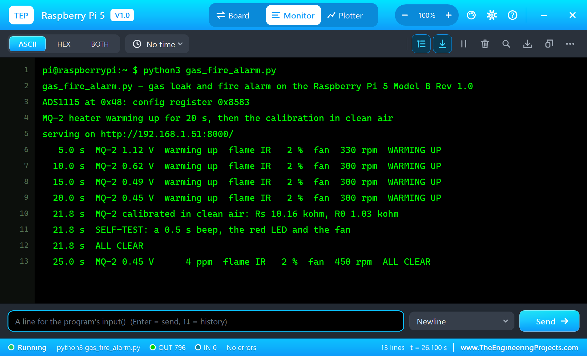
While the heater warmed up, the MQ-2's output fell from 1.12 V at 5 seconds to 0.45 V at 20 seconds, exactly the high-then-settling curve of a real sensor. At 21.8 seconds, the program calibrated it in clean air: Rs 10.16 kohm, so R0 = 10.16 / 9.83 = 1.03 kohm. After the self-test beep, the state became ALL CLEAR: 4 ppm, no flame, the fan at its minimum of 300 rpm.
The Dashboard and the Parts
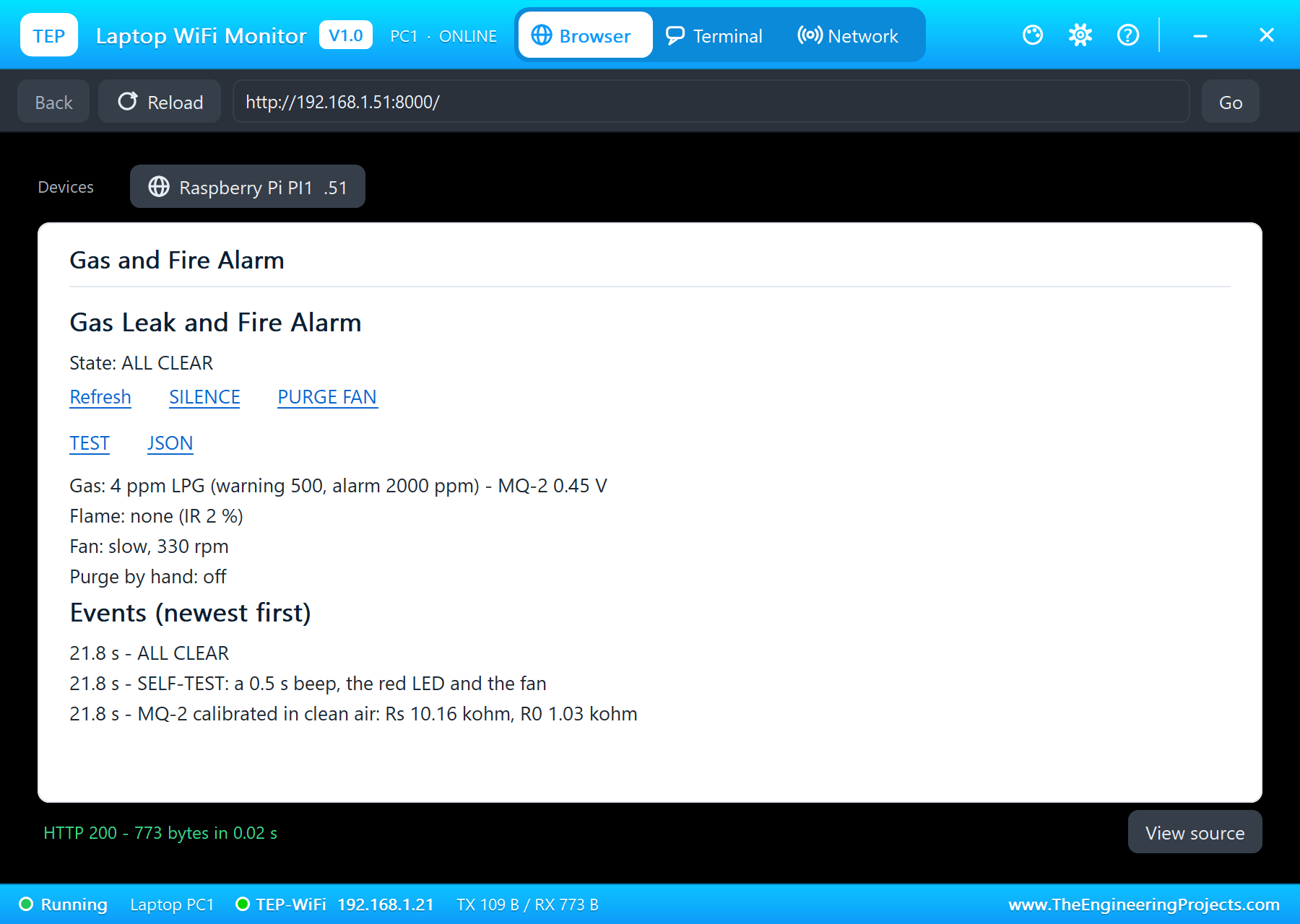
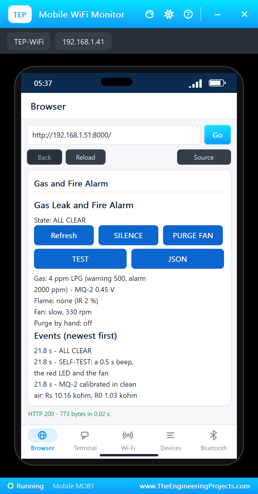
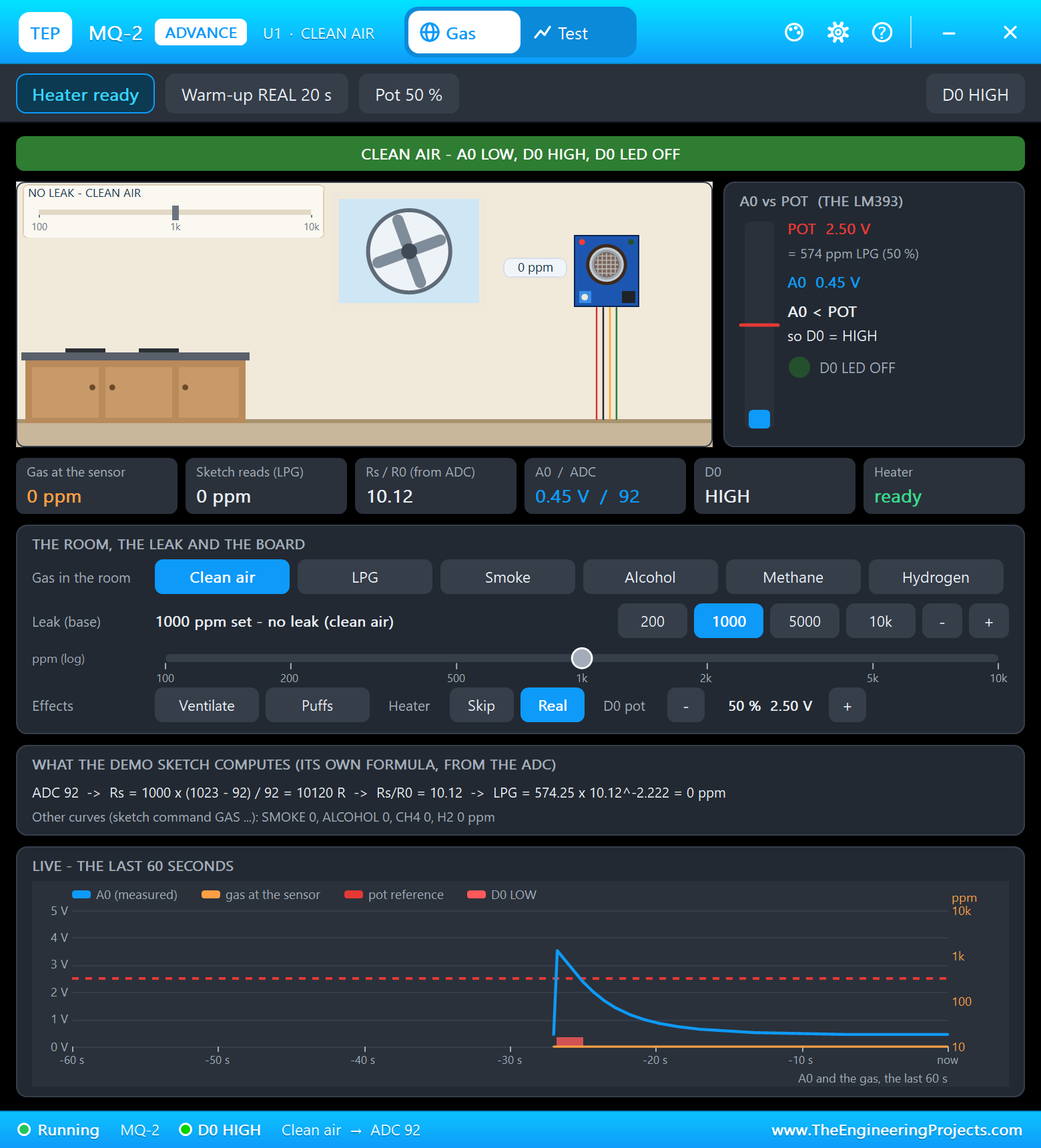
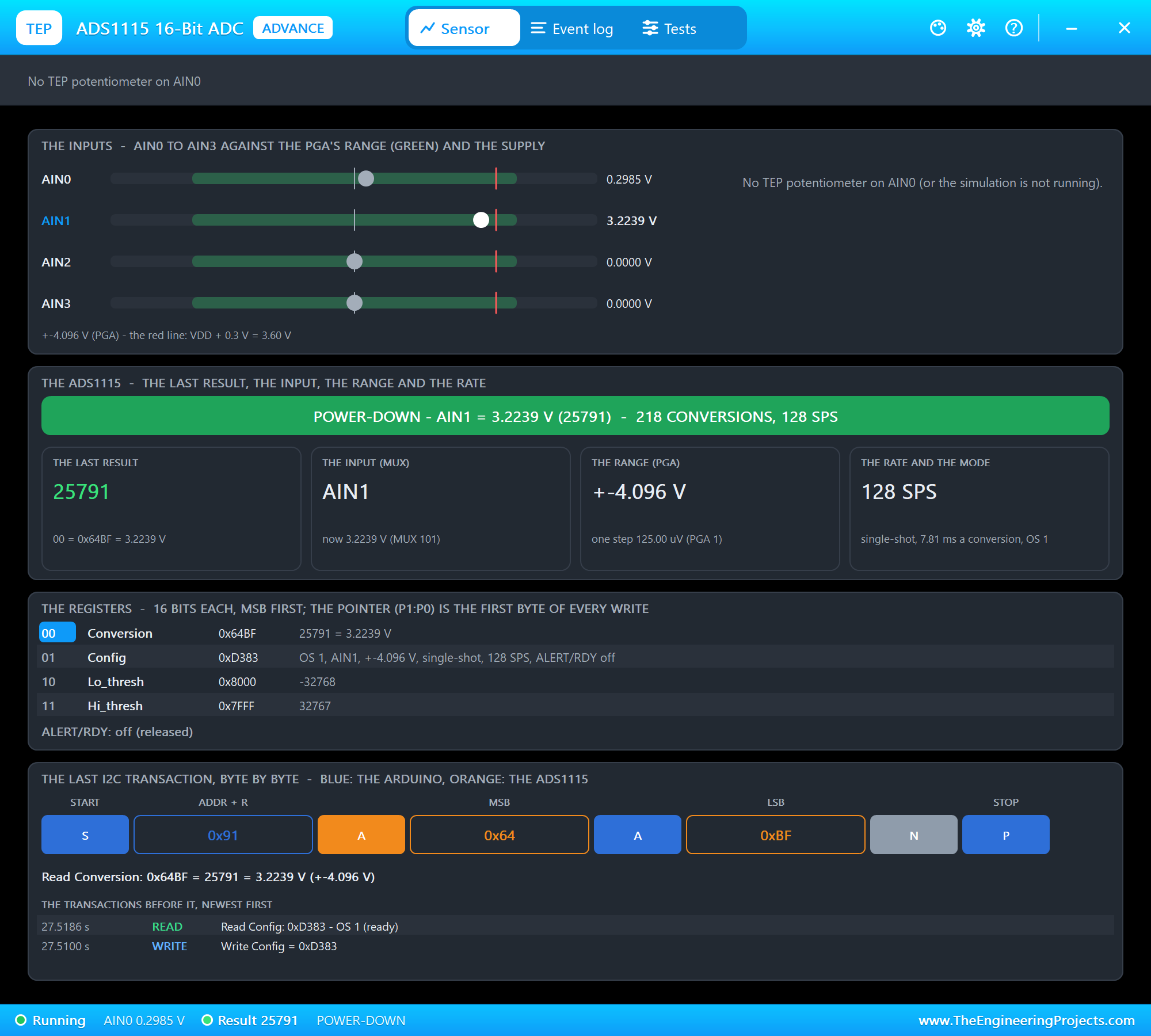
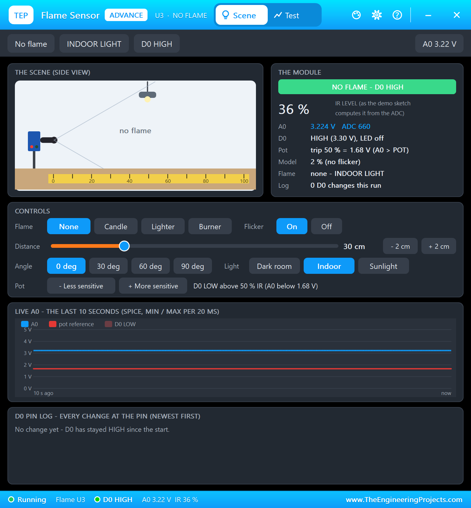
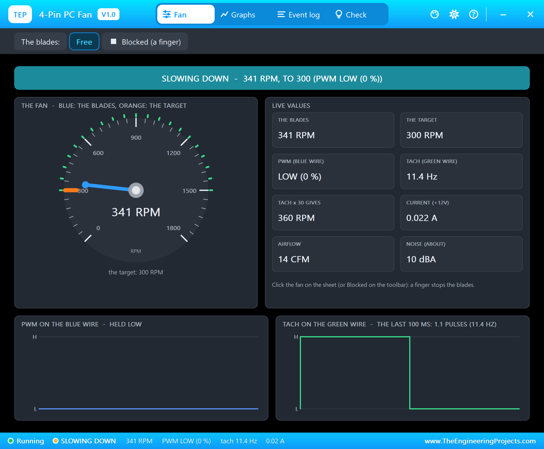
The ADS1115 pop-up lists every conversion: the MQ-2's divided output on A0 and the flame sensor on A1, each a single-shot reading at 128 samples per second on the +-4.096 V range. It even decodes the program's config word: 0xD383 for AIN1 (0xC383 for AIN0) is OS 1, AIN1, +-4.096 V, single-shot, 128 SPS, the comparator off. In clean air, A0 read 0.2985 V, two thirds of the MQ-2's 0.45 V. The fan pop-up shows the PWM wire held LOW and the tach's pulses, 10 a second at 300 rpm.
A Gas Leak
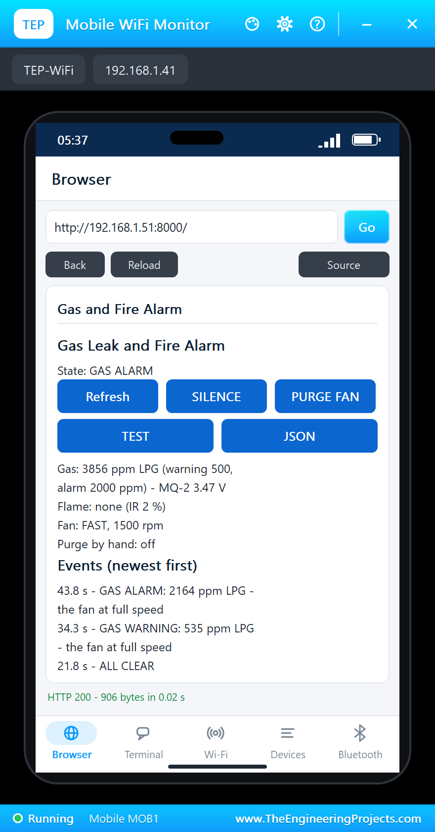
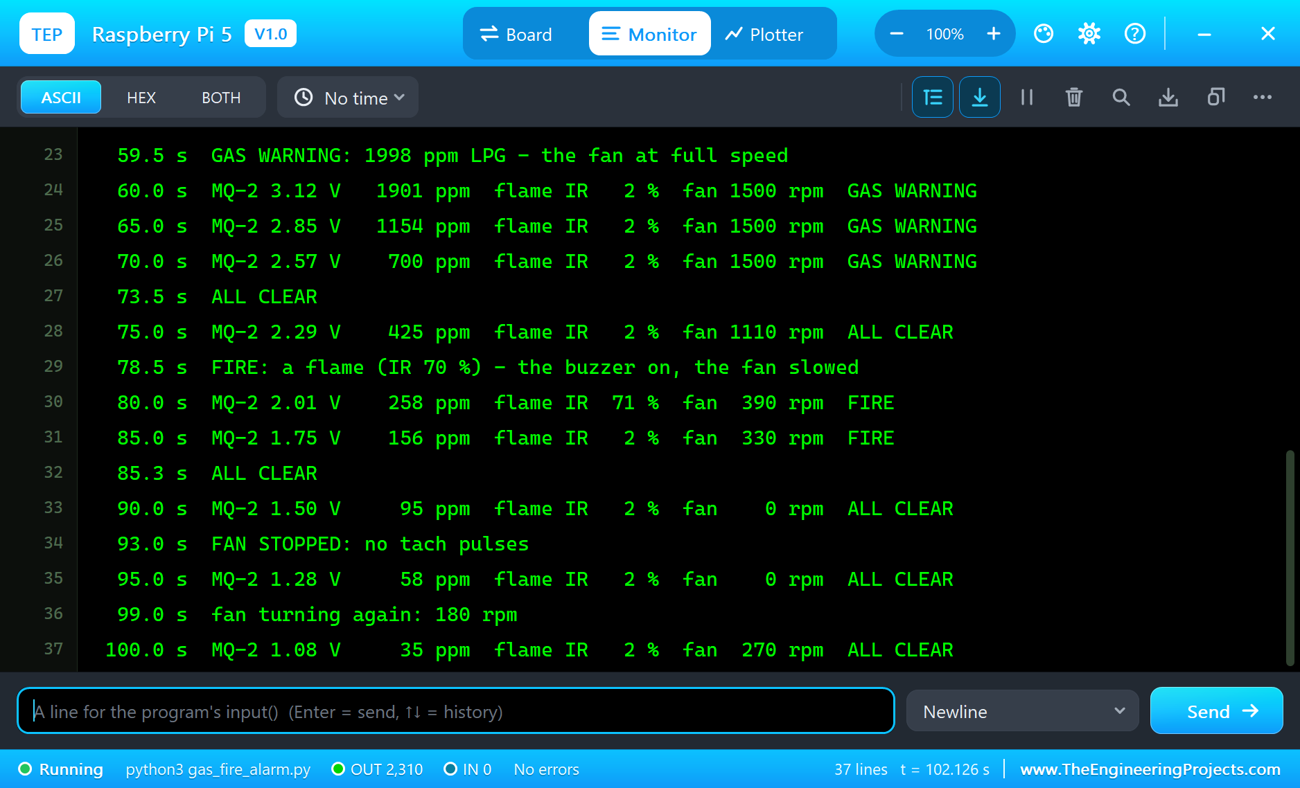
Now the leak. LPG at 1000 ppm in the MQ-2's pop-up: like a real sensor, the output rises over a few seconds, and at 34.3 seconds the reading passed 500 ppm: GAS WARNING at 535 ppm. The fan went to full speed, from 300 to 1,470 rpm within six seconds, and the red LED blinked; the reading reached 930 ppm at 40 seconds.
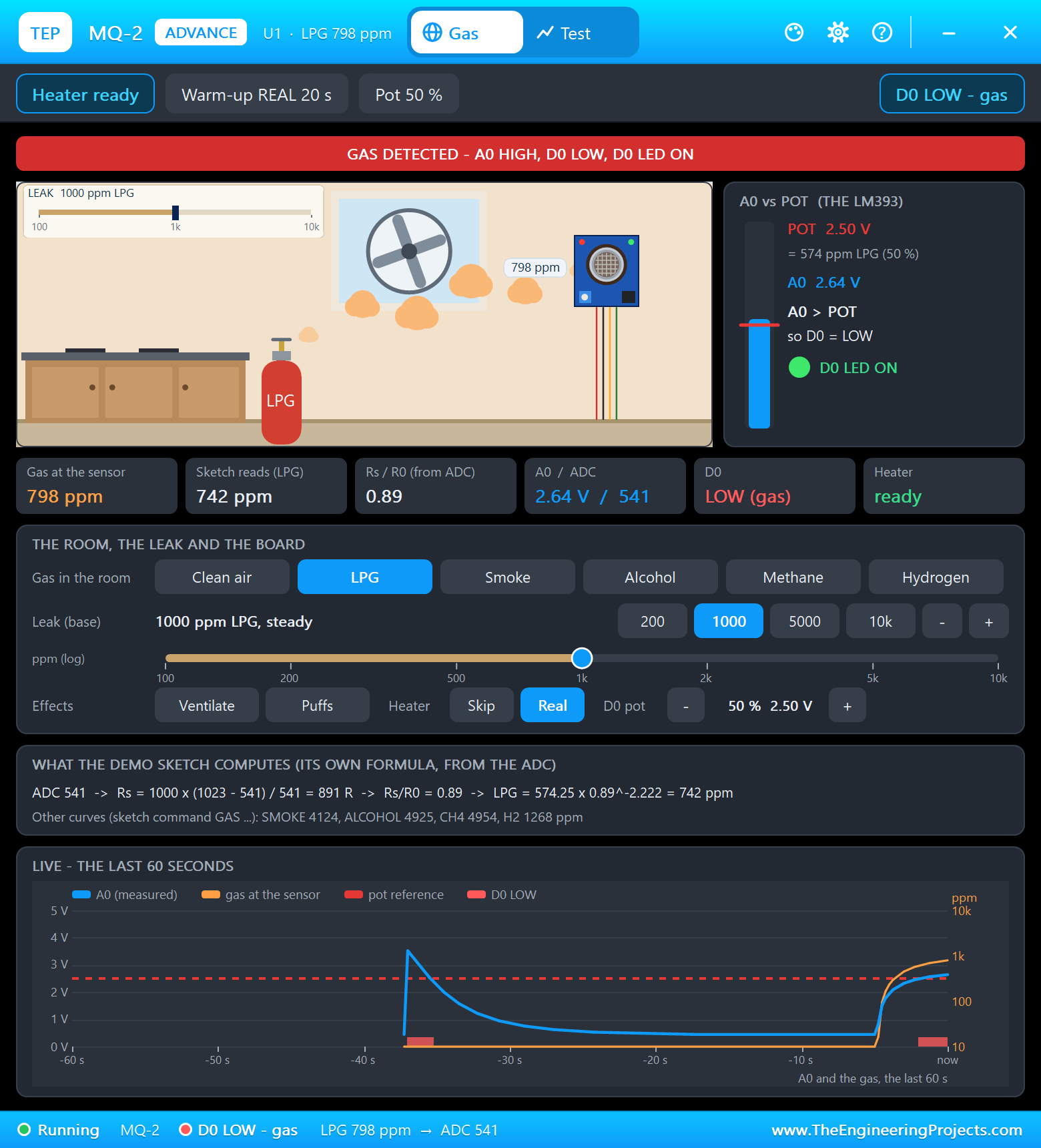
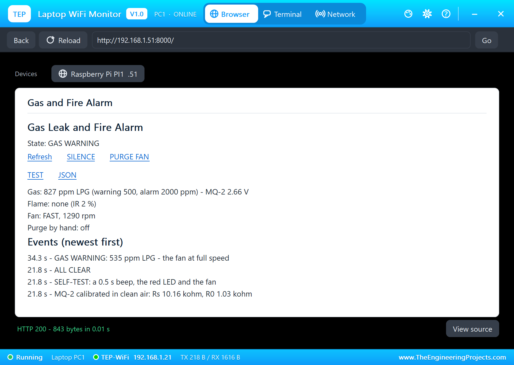
Then 5000 ppm. At 43.8 seconds the reading passed 2000 ppm: GAS ALARM at 2,164 ppm, and the buzzer started beeping. The gas reached 4,630 ppm at 50 seconds, with the MQ-2's output at 3.56 V, and the ADS1115 saw two thirds of it, 2.37 V.
Silencing the Buzzer
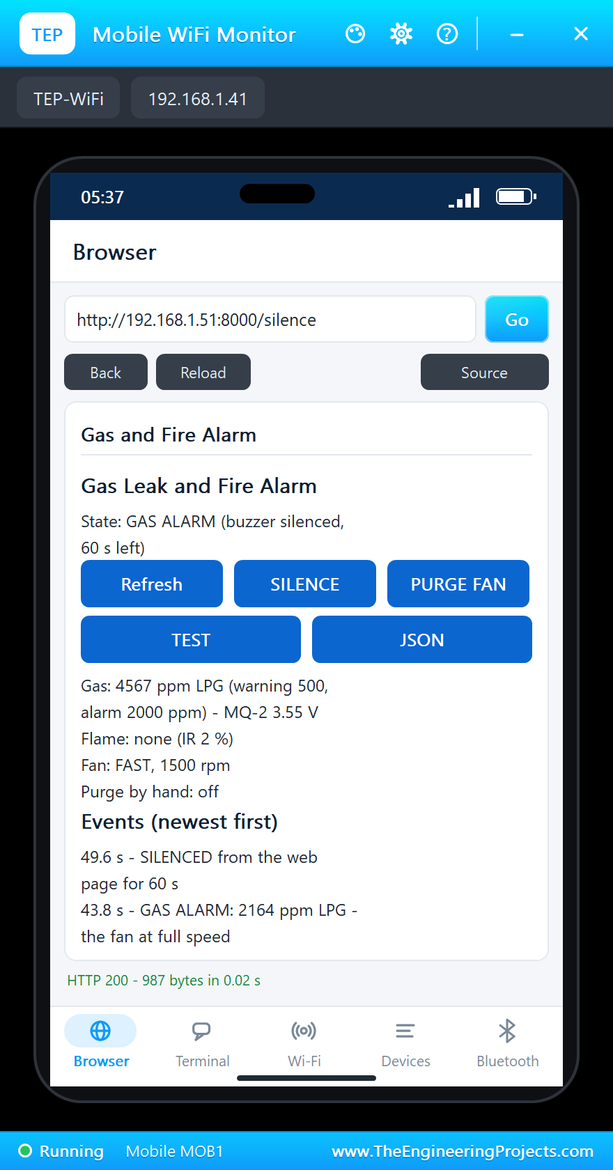
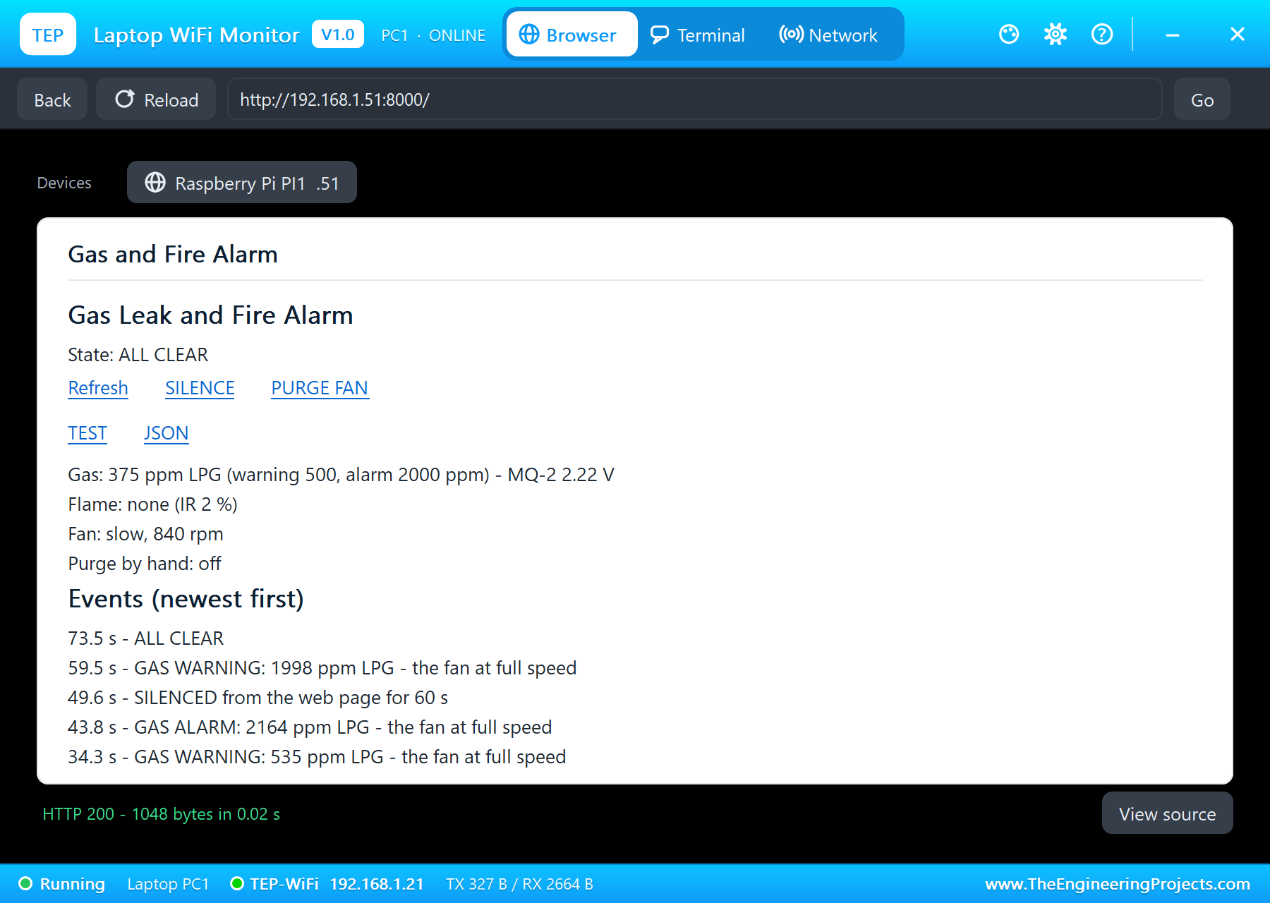
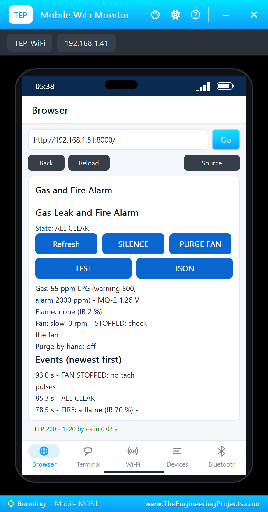
SILENCE on the phone, at 49.6 seconds: the buzzer went quiet for 60 seconds, but the page still says GAS ALARM, with the seconds left, and the red LED stays on. A silenced alarm is still an alarm.
Clean air in the MQ-2's pop-up: the gas falls more slowly than it rose, as a real sensor recovers. GAS WARNING came back at 59.5 seconds (1,998 ppm), and at 73.5 seconds the alarm cleared: ALL CLEAR, the silence cancelled, the fan slowing back to its minimum.
A Fire
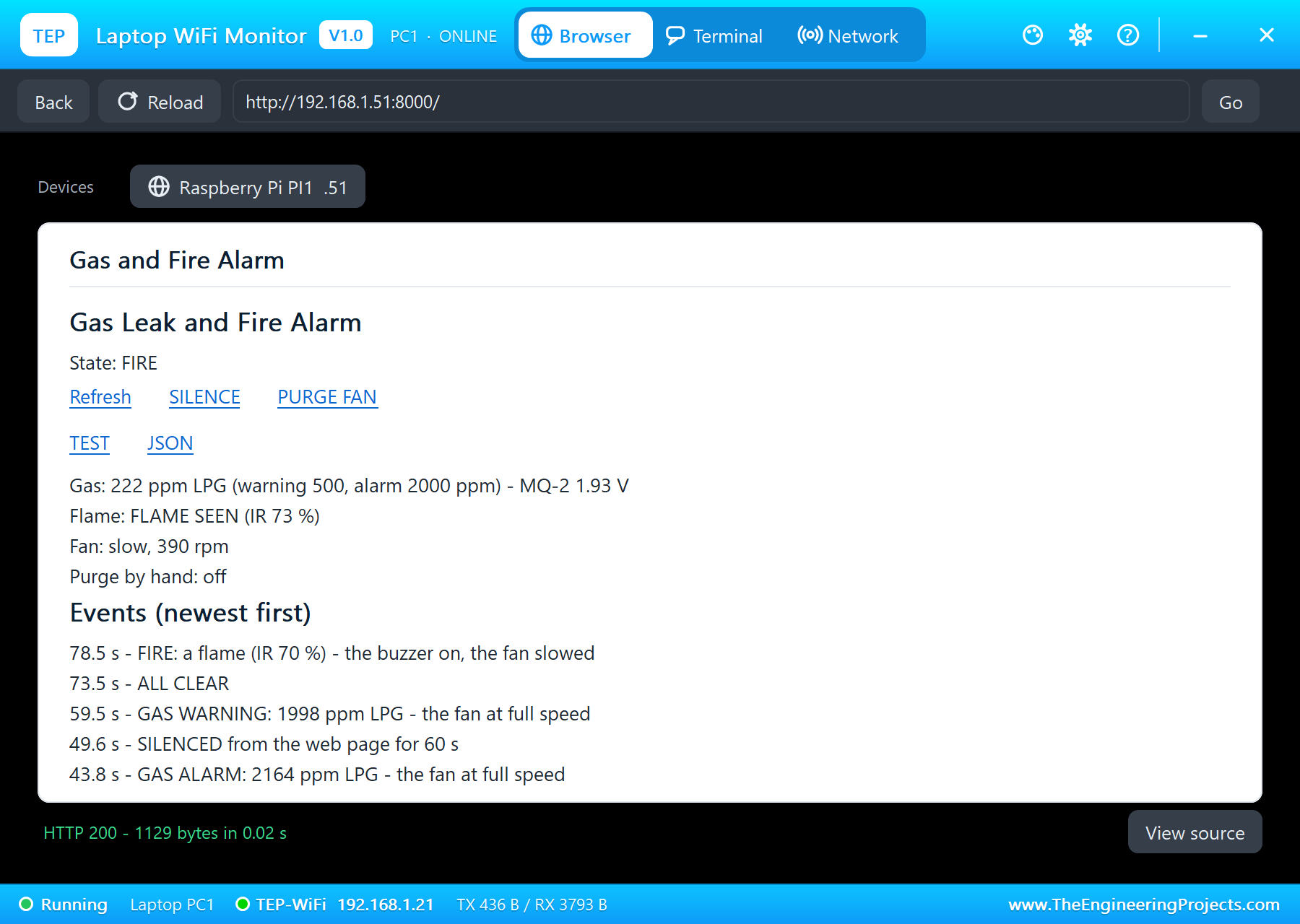
A candle in the flame sensor's pop-up, 30 cm away: at 78.5 seconds the infrared strength reached 70 % and the state became FIRE. The buzzer sounded without a break and, unlike the gas alarm, the fan slowed down, to 390 rpm, so as not to feed the flame with air.
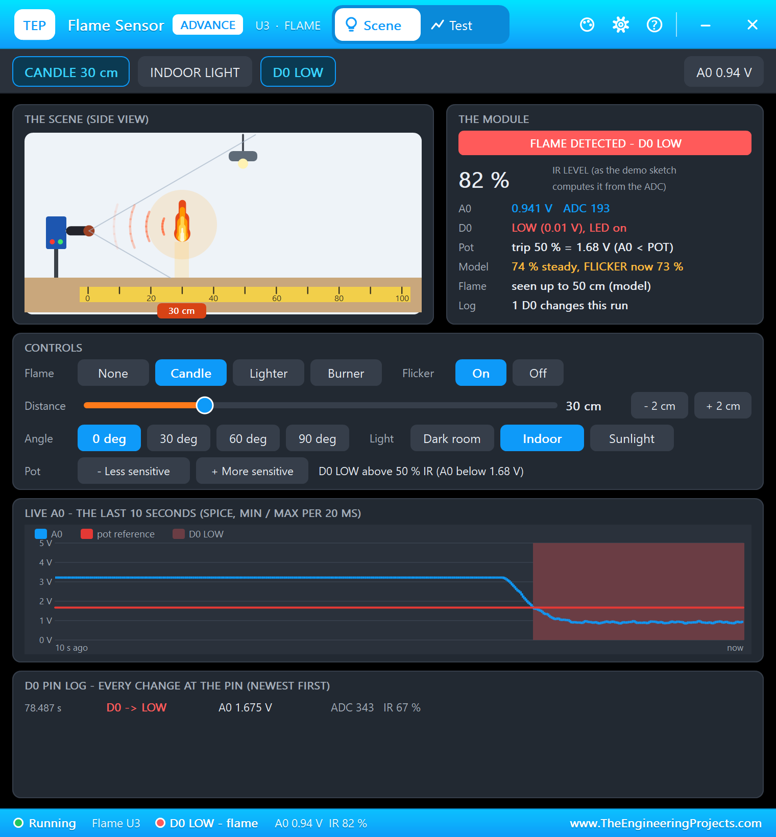
With the flame gone, the infrared fell below 35 % and the state went back to ALL CLEAR at 85.3 seconds.
A Blocked Fan
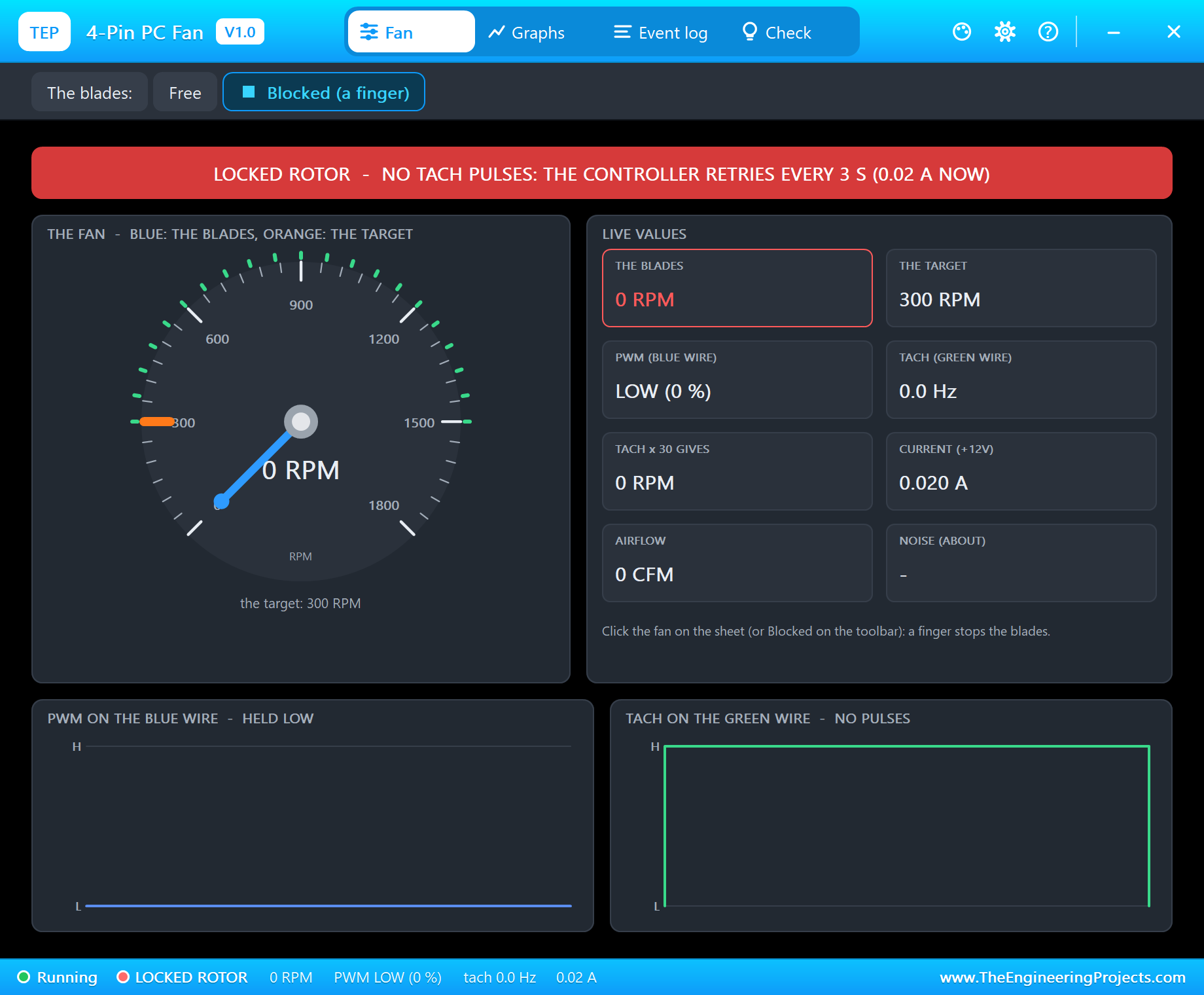
Last, the fan's pop-up: Blocked, like a finger in the blades. The tach pulses stopped, and three seconds later, at 93.0 seconds, the program reported FAN STOPPED. With Free, the fan started again and the warning cleared at 99.0 seconds. A fan that only gets a command, with no check, would fail silently.
| Moment | Reading | State |
|---|---|---|
| 21.8 s, calibration | Rs 10.16 kohm, R0 1.03 kohm, 4 ppm | ALL CLEAR |
| 34.3 s, LPG 1000 ppm | 535 ppm, the fan to 1,470 rpm | GAS WARNING |
| 43.8 s, LPG 5000 ppm | 2,164 ppm, 4,630 ppm at 50 s | GAS ALARM |
| 49.6 s, SILENCE | the buzzer quiet for 60 s | GAS ALARM (silenced) |
| 73.5 s, clean air | below 500 ppm | ALL CLEAR |
| 78.5 s, a candle | IR 70 %, the fan to 390 rpm | FIRE |
| 93.0 s, the fan blocked | 0 rpm, no tach pulses | FAN STOPPED |
Download the Project Files
Click the button below to download Raspberry-Pi-5-Gas-Leak-Fire-Alarm-Proteus-Simulation-v1.0.zip (about 15.4 MB, without the source code of the models):
Raspberry Pi 5 Gas Leak and Fire Alarm - Proteus Simulation V1.0- Proteus Simulation: Pi-5-Gas-Leak-Fire-Alarm.pdsprj, the program gas_fire_alarm.py and copies of the models.
- Python Code: gas_fire_alarm.py, the complete program.
- Proteus Library Files: the LIB files of the Raspberry Pi 5, the MQ-2, the flame sensor, the ADS1115, the fan, the buzzer, the transistor, the LEDs, the resistors and the two WiFi Monitors.
- Proteus Model Files: the DLL models and the TEPPi folder, the Python 3.11 and the runtime that the Pi board runs.
- README.txt: the installation steps, the properties, the test results and the links to every library post.
No Proteus yet? Read How to Download and Install Proteus 7 and 8. New to libraries? Follow How to Install a New Library in Proteus.
How to Install the Project Files
- Close Proteus and extract the whole zip file, for example to your Desktop.
- Copy the files from Proteus Library Files into the LIBRARY folder of Proteus.
- Copy everything in Proteus Model Files, the DLL files and the TEPPi folder, into the MODELS folder.
- Start Proteus and open the project from the Proteus Simulation folder.
Changing the Code
The program is plain Python 3: edit gas_fire_alarm.py beside the project and press Play again; the Pi board runs the new file. The same program runs on a real Raspberry Pi 5 with Raspberry Pi OS, where lgpio is already installed. For another Raspberry Pi 5 project with a web page, see our Raspberry Pi 5 RFID Door Access.
Ideas to Extend the Project
- Add a second MQ-2 curve and show smoke as well as LPG.
- Close a gas valve with a solenoid when the alarm sounds.
- Send a message to a phone app or an email server when the state changes.
- Log the gas level every minute and draw a graph on the page.
- Add a temperature sensor and raise the fire alarm on a fast temperature rise as well.
- Use the Pi 5's hardware PWM for a true 25 kHz fan signal and a smooth speed control.
From Simulation to Real Hardware
- A real alarm must be a certified product: this project is for learning; never rely on it to protect people.
- Burn the MQ-2 in: a new sensor wants 24 to 48 hours of heating before its readings settle, and a few minutes after each power-up.
- Mind the heater: it draws about 150 mA at 5 V and gets hot; give it room and air.
- Calibrate in clean air: gas at the calibration makes every later reading too low.
- Place the sensors right: LPG is heavier than air, so put a gas sensor low; natural gas is lighter, so put it high.
- Fan PWM: real 4-pin fans want 25 kHz; the Pi 5's hardware PWM on GPIO18 can make it, while lgpio's software PWM stops at 10 kHz.
Troubleshooting
- The program stops at the start: the ADS1115 does not answer; check SDA / SCL and that ADDR is on ground (0x48).
- The gas reads high after Play: that is the warm-up; the program waits 20 s before it calibrates.
- The fan's rpm stays 0: the tach has no pull-up, or the fan has no 12 V (its pop-up says NO 12 V).
- The flame alarm trips in sunlight: sunlight is full of infrared; raise
FLAME_ONin the program. - The terminal cannot start Python: the TEPPi folder is not in MODELS.
Limitations of the Simulation
- The gas and the flame come from the sensors' pop-ups; a real leak spreads through a room over minutes.
- The MQ-2's warm-up is 20 seconds here instead of minutes, so the run stays short.
- The fan's PWM wire is held LOW or HIGH: two speeds, no 25 kHz signal.
- The network is simulated: the dashboard travels between the Pi and the two monitors inside Proteus; the times in this tutorial are simulation time.
- Raspberry Pi is a trademark of Raspberry Pi Ltd; MQ-2 and ADS1115 are names of their owners; this project is not made or endorsed by them or by Labcenter.
So, that was all about the Raspberry Pi 5 Gas Leak and Fire Alarm - Proteus Simulation. I hope it helps you build your own alarm: analog sensors through an ADS1115, a calibrated gas reading in ppm, a fan with a tach check and a web dashboard, all tested in a simulation before any real gas comes near it. More IoT projects with the ESP32 and the Raspberry Pi 5 are coming in this series. If you have any questions, ask in the comments and I will help you out. Till the next tutorial, take care and have fun!