Hello friends, I hope you all are doing great. Today, I am going to share the new Resistor Library for Proteus. Proteus has a resistor of its own, of course: a plain little box with a value next to it. It works very well, but it looks nothing like the part in your hand. So we drew the real thing: a small axial resistor with a proper body, tinned leads and colour bands that follow its value.
Resistor Library for Proteus
Latest version: V1.0 (November 2026, this tutorial)
Other component libraries: C945 Transistor · PC817 Optocoupler · Relay Module · 5 mm LED · Designer Colour LED · Push Button · Active Buzzer · Electrolytic Capacitor · Ceramic Capacitor · Tantalum Capacitor · Film Capacitor · 1N4007 Diode · Zener Diode · Schottky Diode · Supercapacitor · Photodiode · RGB LED · Bridge Rectifier · Flashing LED · Bi-Colour LED · SMD LED · Slide Switch · Toggle Switch · Rocker Switch · Micro Limit Switch · Emergency Stop Switch · SMD Resistor · Power Resistor · Resistor Network · Potentiometer · Trimmer Potentiometer · Slide Potentiometer · NTC Thermistor · DIP Switch · Fuse · Passive Buzzer · Mini Speaker · 7-Segment Display · LED Bar Graph · IR / UV LED · Small Transistors · TIP122 Darlington · N-MOSFET · P-MOSFET · PC817 Optocoupler · Filament Bulb · Power LED · Voltage Regulator · SCR and TRIAC · Inductor · Toroid Inductor · Crystal
Helping Tools
- Serial Monitor Advance: a serial terminal window for the UART of your board
- Serial Monitor Expert: the serial monitor with extra debugging tools
- LCD Library for Proteus V3.0: 16x2, 20x4 and I2C LCDs to show your readings
And it is not only a pretty picture. The part heats up with the power it burns, it warns you when you overload it, and if you push it far enough it burns out and opens the circuit, just like a real one. Click it while the simulation runs and a pop-up decodes the bands one by one, with the volts, amps, watts and the temperature of the body. This is the first library of a new series of basic components.
NOTICE: Our team has put a lot of effort into these small parts: the bodies, the bands, the heat and the pop-ups are all our own design, and you get them free. Your feedback is the fuel that keeps us going, so please tell us what you think in the comments below or in the Resistor board of our forum. And if our free libraries help you, you can buy us a coffee. So, let's get started with the Resistor Library for Proteus:
What is a Resistor?
A resistor is the simplest part in electronics. It opposes the flow of current, and it turns the electrical energy it takes into heat. You will find one in almost every circuit: limiting the current through an LED, pulling a pin up or down, dividing a voltage, setting the gain of an amplifier. Its value is measured in ohms, and three simple rules cover nearly everything you will ever do with one.
| Rule | Formula | What it tells you |
|---|---|---|
| Ohm's law | V = I x R | the voltage across a resistor from the current through it |
| Power | P = V x I = V x V / R | the heat it must get rid of, in watts |
| Voltage divider | Vout = Vin x R2 / (R1 + R2) | the voltage at the middle of two resistors in series |
A resistor has no polarity, so it works either way round. The two things that decide which one you buy are its value and its power rating. A third, the tolerance, tells you how close to that value the part is guaranteed to be.
The Colour Code
A small resistor has no room for printed numbers, so its value is painted on as coloured bands. Each colour stands for a number. Read from the end where the bands are bunched together: the first bands are the digits of the value, the next one is the multiplier, and the last one, a little apart from the others, is the tolerance.
| Colour | Digit | Multiplier | Tolerance |
|---|---|---|---|
| Black | 0 | x 1 | |
| Brown | 1 | x 10 | 1 % |
| Red | 2 | x 100 | 2 % |
| Orange | 3 | x 1k | |
| Yellow | 4 | x 10k | |
| Green | 5 | x 100k | 0.5 % |
| Blue | 6 | x 1M | 0.25 % |
| Violet | 7 | x 10M | 0.1 % |
| Grey | 8 | x 100M | |
| White | 9 | x 1G | |
| Gold | x 0.1 | 5 % | |
| Silver | x 0.01 | 10 % |
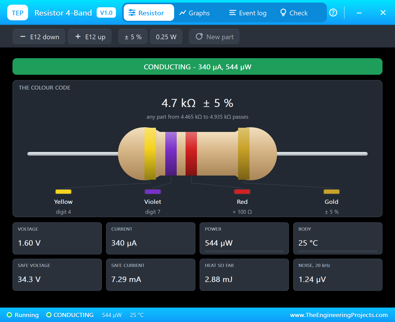
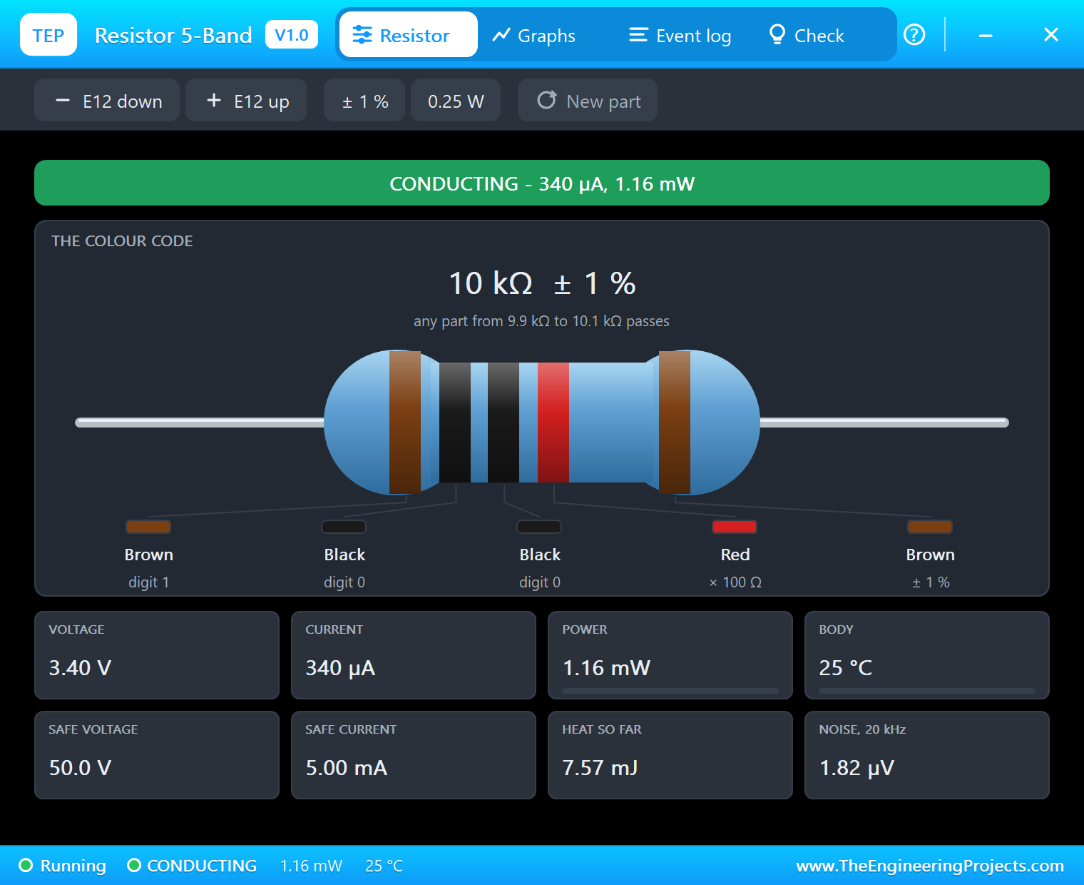
Here is one worked example. Yellow, Violet, Red and Gold read 4, 7, then a multiplier of 100, then 5 %. That makes 47 x 100 = 4700 ohms, or 4.7k, and any part between 4465 and 4935 ohms passes. A 5-band resistor simply has a third digit, which suits the tighter 1 % parts: Brown, Black, Black, Red and Brown read 100 x 100 = 10k at 1 %.
The E12 Series
You cannot buy a resistor of any value you like. Shops stock the values of a preferred series, spaced so that each one is about the same percentage above the last. The common one is E12, with twelve values in each decade: 10, 12, 15, 18, 22, 27, 33, 39, 47, 56, 68 and 82. That is why you meet 4.7k and 330 ohms everywhere, but never 5k. The finer E24 series has twenty-four. The Check page of our pop-up tells you when a value is not one you can buy, and gives you the nearest ones.
Power Rating
Every resistor turns its power into heat, and the body can only shed that heat so fast. A common through-hole part is rated at 0.25 W. At that power it runs hot, and a good designer keeps it well below the limit: under half the rating is a sensible rule. Go over the limit and the part cooks. It discolours first, then chars, and finally the resistive film breaks and the circuit opens. That is exactly what our model does.
Features of the Resistor Library for Proteus
- The real look: a beige carbon film part with four bands and a blue metal film part with five, in the small size you know, with tinned leads and our small TEP signature.
- True colour code: the bands follow your value and tolerance, with gold and silver multipliers for small values and one black band for a 0 ohm link.
- Any way of writing a value: 1k, 4k7, 2.2M, 0R47, R47, 1000 and 1Meg all work.
- Bands on the stopped sheet: a dropdown of 76 shop values sets the look without a Run, and a Run sets it for you.
- It heats up: the body warms with the power it burns, and takes on colour as it gets hot.
- It burns out: past 350 C the body chars and the part opens, with a clear warning in the Event log.
- A pop-up for every part: click it at Run for the decoded bands, eight live values, graphs, an event log and a check page.
- Live changes: step the value through the E12 series while the simulation runs, and watch the circuit react.
- A complete package: about 1.2 MB with the library, our Arduino UNO V4.0 and the demo, without the source code of the models.
The Resistor in Proteus
The library has two devices in TEPRESISTOR.LIB, under Resistors, Generic, with the prefix R, and both run on one model, TEPRESISTOR.DLL. Search RESISTOR4BAND or RESISTOR5BAND in Pick Devices. Like the real parts they are small: 600 thou from pin to pin, drawn to scale against our Arduino, so a sheet of them stays neat.
| Device | Looks like | Bands | Default tolerance |
|---|---|---|---|
| RESISTOR4BANDTEP | beige carbon film | four: two digits, multiplier, tolerance | 5 % |
| RESISTOR5BANDTEP | blue metal film | five: three digits, multiplier, tolerance | 1 % |
The Properties
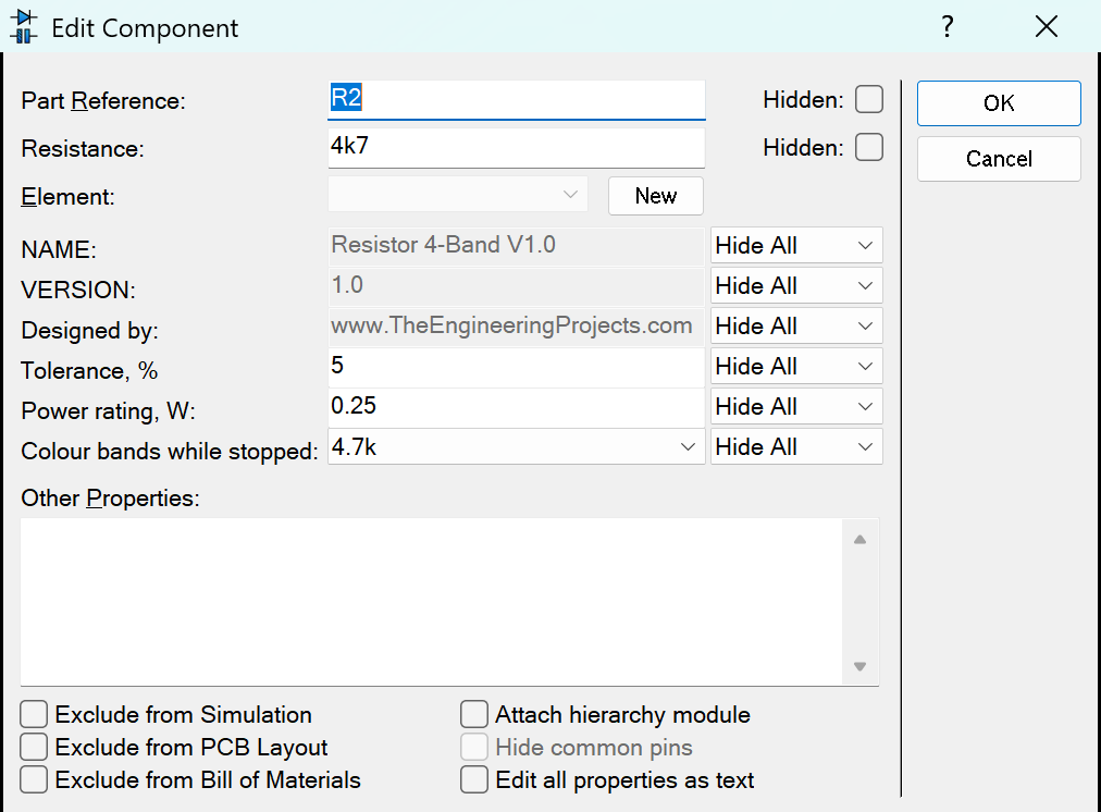
Double-click a resistor to change it. The Resistance box takes the value in any of the usual ways. The tolerance and power rating are plain numbers.
| Property | What it does |
|---|---|
| Resistance | the value: 1k, 4k7, 2.2M, 0R47, R47, 1000, 1Meg |
| Tolerance, % | 4-band: 5 or 10. 5-band: 1, 2, 0.5, 0.25 or 0.1 |
| Power rating, W | 0.125, 0.25, 0.5, 1 or 2 |
| Colour bands while stopped | the dropdown: the look of the part before you press Run |
The Bands at Run, and While Stopped
There is one thing worth knowing here, and it comes from how Proteus works. A model only runs during a simulation, so nothing of ours can repaint a part while the sheet is stopped. We found a neat way round it.
At Run the bands always follow what you typed, whatever the value. While stopped, the part shows one of 76 ready-drawn looks: every E12 value from 1 ohm to 820k, then 1M, 2.2M, 4.7M and 10M. You choose one with the Colour bands while stopped dropdown, and the bands change on the sheet as soon as you press OK. Better still, you often do not need the dropdown at all: press Run once, and the model sets it to the value nearest what you typed. It stays that way after Stop, and after you save the project.
Download Resistor Library for Proteus
Click the button below to download Resistor-Library-for-Proteus-v1.0.zip (about 1.2 MB, without the source code of the models):
Resistor Library for Proteus V1.0- README.txt: installation, the demo, the properties, troubleshooting and the limits.
- Proteus Library Files:
TEPRESISTOR.LIBand ourArduinoV4TEP.LIBwith the ARDUINO UNO V4.0. - Proteus Model Files:
TEPRESISTOR.DLLandTEPARDUINO.DLL. - Arduino Code: the demo sketch.
- Proteus Simulation: the demo project, its HEX file and copies of the DLLs.
No Proteus yet? Read How to Download and Install Proteus 7 and 8. New to libraries? Follow How to Install a New Library in Proteus.
How to Install Resistor Library for Proteus
- Close Proteus and extract the whole zip file, for example to your Desktop.
- Copy the files from Proteus Library Files into the LIBRARY folder of Proteus.
- Copy the files from Proteus Model Files into the MODELS folder.
- Delete
TEPRESISTOR.IDXfrom the LIBRARY folder if it is there. - Start Proteus, press P and search for RESISTOR4BAND.
Demo: an Ohmmeter and an Overload Watch
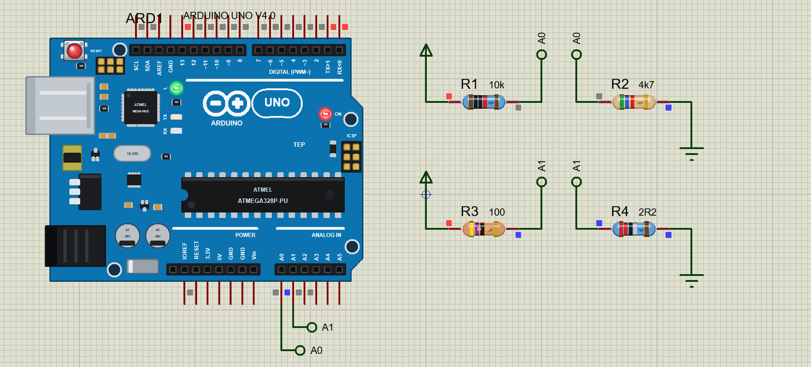
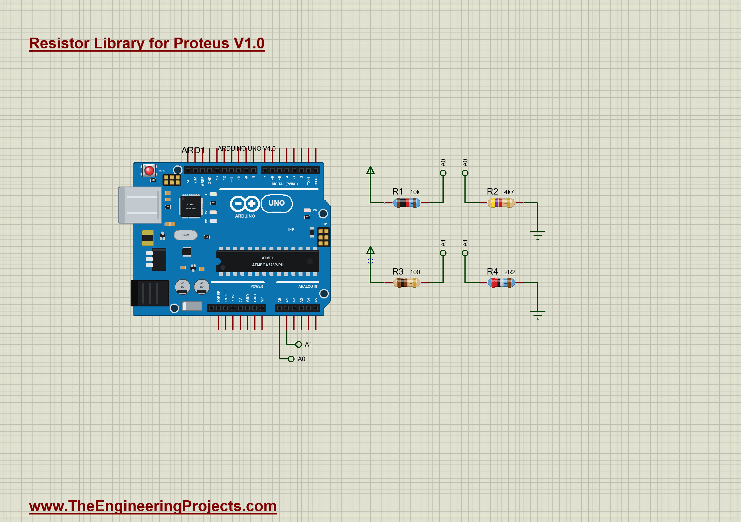
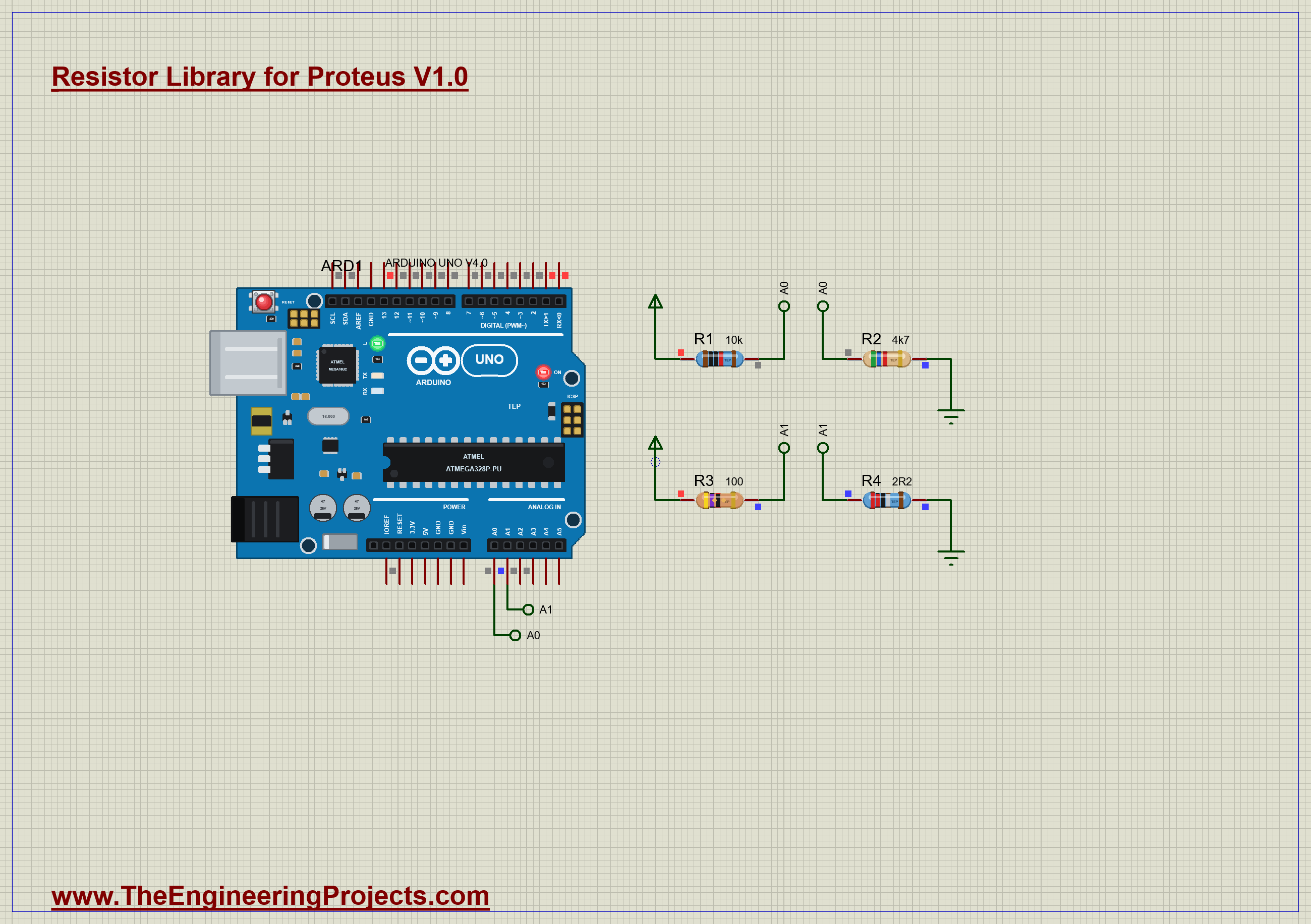
The demo does two small jobs on one Arduino, and both are classics you can build on a breadboard. The first measures an unknown resistor. The second watches the power in a resistor, and tells you when it is in trouble. Open Resistor-Ohmmeter-ArduinoUnoV4.pdsprj. It runs on our Arduino UNO Library for Proteus V4.0, and the results appear in its built-in monitor, the same window as our TEP Serial Monitor Advance for Proteus.
| Part | Value | Job |
|---|---|---|
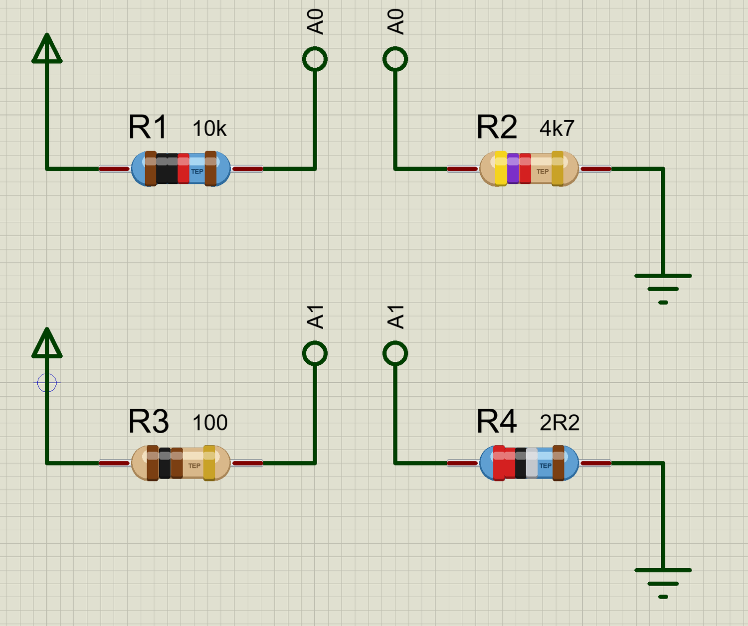
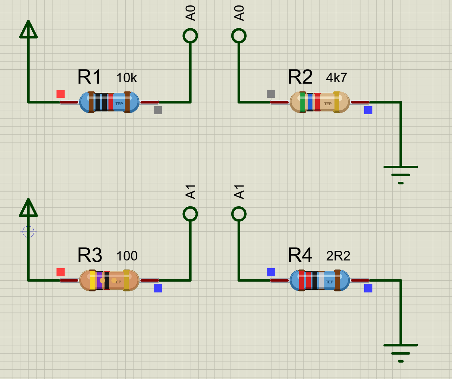
| R1 | 10k, 5-band | the known resistor of the ohmmeter, from +5V to A0 |
| R2 | 4k7, 4-band | the unknown resistor, from A0 to GND |
| R3 | 100 ohm, 0.25 W | the part we will overload, from +5V to A1 |
| R4 | 2R2, 1 W, 5-band | the current sense resistor, from A1 to GND |
The Ohmmeter
R1 and R2 make a voltage divider, so the voltage at A0 depends on R2. The Arduino reads it as a number from 0 to 1023. Turn the divider formula round and the supply voltage cancels out, which is a nice bonus: R2 = R1 x reading / (1023 - reading). The sketch averages 16 readings to steady the result:
void meter() {
  float adc = readAverage(A0);
  if (adc < 2.0 || adc > 1021.0) { Serial.println(F("R2: nothing measurable on A0")); return; }
  float r2 = R_KNOWN * adc / (1023.0 - adc);
The check at the start matters on a real bench. Near either end of the range one count of the reading makes a huge change in the answer, so the sketch refuses to guess. An ohmmeter like this one is most accurate when the unknown part is close to the known one.
Next the sketch finds the nearest shop value. It scales the value into the range 10 to 99, keeps count of the powers of ten, and picks the closest number from the E12 list. Those two numbers are all it needs to name the bands: the two digits of the value, then the power of ten as the multiplier:
void nearestE12(float ohms, int& digits, int& power) {
  power = 0;
  while (ohms >= 100.0) { ohms /= 10.0; power++; }
  while (ohms < 10.0) { ohms *= 10.0; power--; }
The Overload Watch
R3 and R4 are in series, so the same current flows through both. R4 is tiny at 2.2 ohms, so it hardly changes the circuit, but the voltage across it tells us the current by Ohm's law. This is how real circuits measure current, and the small resistor is called a sense resistor. From the current the sketch works out the voltage across R3, and so the power it burns:
  float vR3 = VCC - amps * R_SENSE;
  float watts = vR3 * amps;
  digitalWrite(LED_BUILTIN, watts > R_RATING ? HIGH : LOW);
If the current disappears after it has been flowing, something has opened. That is the sign of a burnt resistor:
    if (started && !burnt) {
      burnt = true;
      Serial.println(F("R3 BURNT OUT: no current on A1 - the resistor is open"));
    }
The built-in LED lights while R3 is over its rating, and everything repeats once a second:
void loop() {
  unsigned long now = millis();
  if (now - lastPrint >= 1000) {
    lastPrint = now;
    meter();
    watch();
  }
}
Run the Demo
Press Run and the monitor opens. Every second it prints R2 and R3:
Resistor Library demo - The Engineering Projects
R2 = 4.70 kohm, nearest E12 = 4.70 kohm, bands Yellow Violet Red
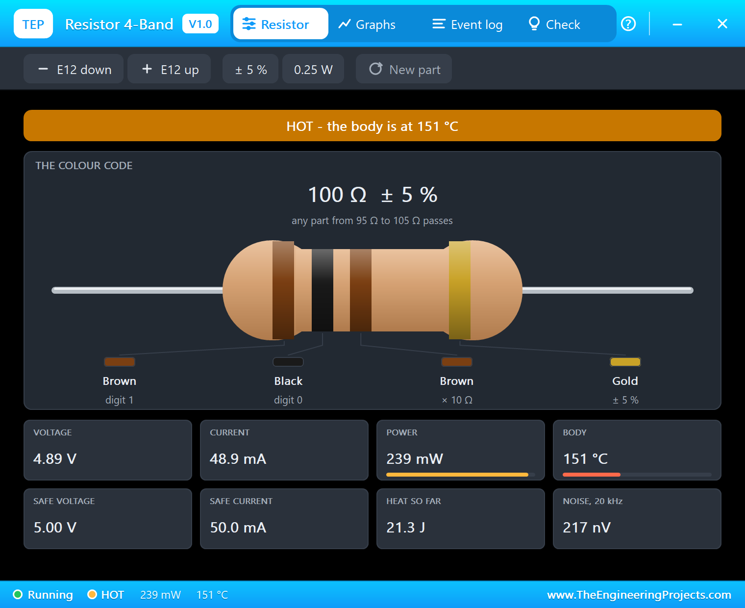
R3: 48.9 mA, 100.1 ohm, 0.239 W
The ohmmeter has read 4.70 kohm and named the bands, and those are the very colours on the part. R3 burns 0.239 W, just under its 0.25 W rating.
Open the Pop-Up
Click the body of R2. A sheet can hold a lot of resistors, so the pop-ups stay closed until you ask for one. The Resistor tab shows the state in big letters, the part with each band decoded, the range a good part falls in, and the live values. Safe voltage and safe current are worked out from the value and the rating, so you can see at once how far this part can go. The thermal noise is there for those who design amplifiers.
R1 is a 5-band part, so its pop-up has one more column. It shows the third digit, and the tighter range of a 1 % resistor:
Change a Value While It Runs
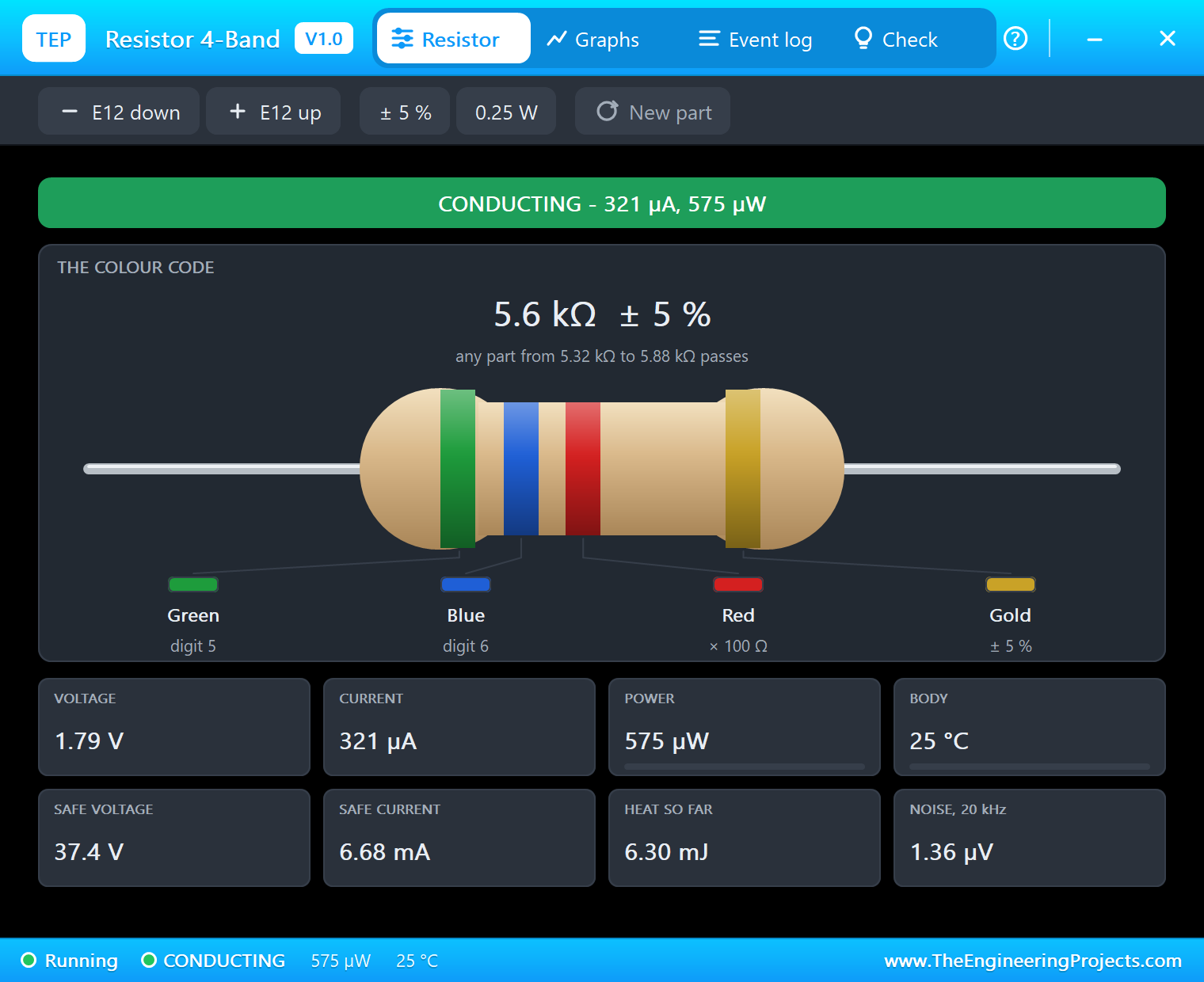
Now for the fun part. Press E12 up on R2's pop-up. The value goes from 4.7k to 5.6k, and the bands change right there on the sheet. A moment later the monitor measures the new part:
R2 = 5.62 kohm, nearest E12 = 5.60 kohm, bands Green Blue RedThe Arduino's reading moves in small steps, so the sketch sees 5.62 kohm for a 5.6k part, and that is just what a real ohmmeter of this kind would give. The pop-up follows too:
Overload R3
Click R3 and press E12 down. At 82 ohms the part burns 0.289 W, which is over its rating. The banner turns red, the Arduino's L LED lights, and the monitor adds OVERLOAD to its line. Keep going, one step at a time, and watch the power climb. Here are the numbers from our run:
| R3 | Current | Power | On a 0.25 W part |
|---|---|---|---|
| 100 ohm | 48.9 mA | 0.239 W | inside the rating |
| 82 ohm | 59.4 mA | 0.289 W | OVERLOAD |
| 68 ohm | 71.2 mA | 0.345 W | OVERLOAD |
| 56 ohm | 85.9 mA | 0.413 W | OVERLOAD |
| 47 ohm | 101.6 mA | 0.485 W | OVERLOAD |
| 39 ohm | 121.4 mA | 0.574 W | OVERLOAD |
| 33 ohm | 142.0 mA | 0.666 W | it will burn out |
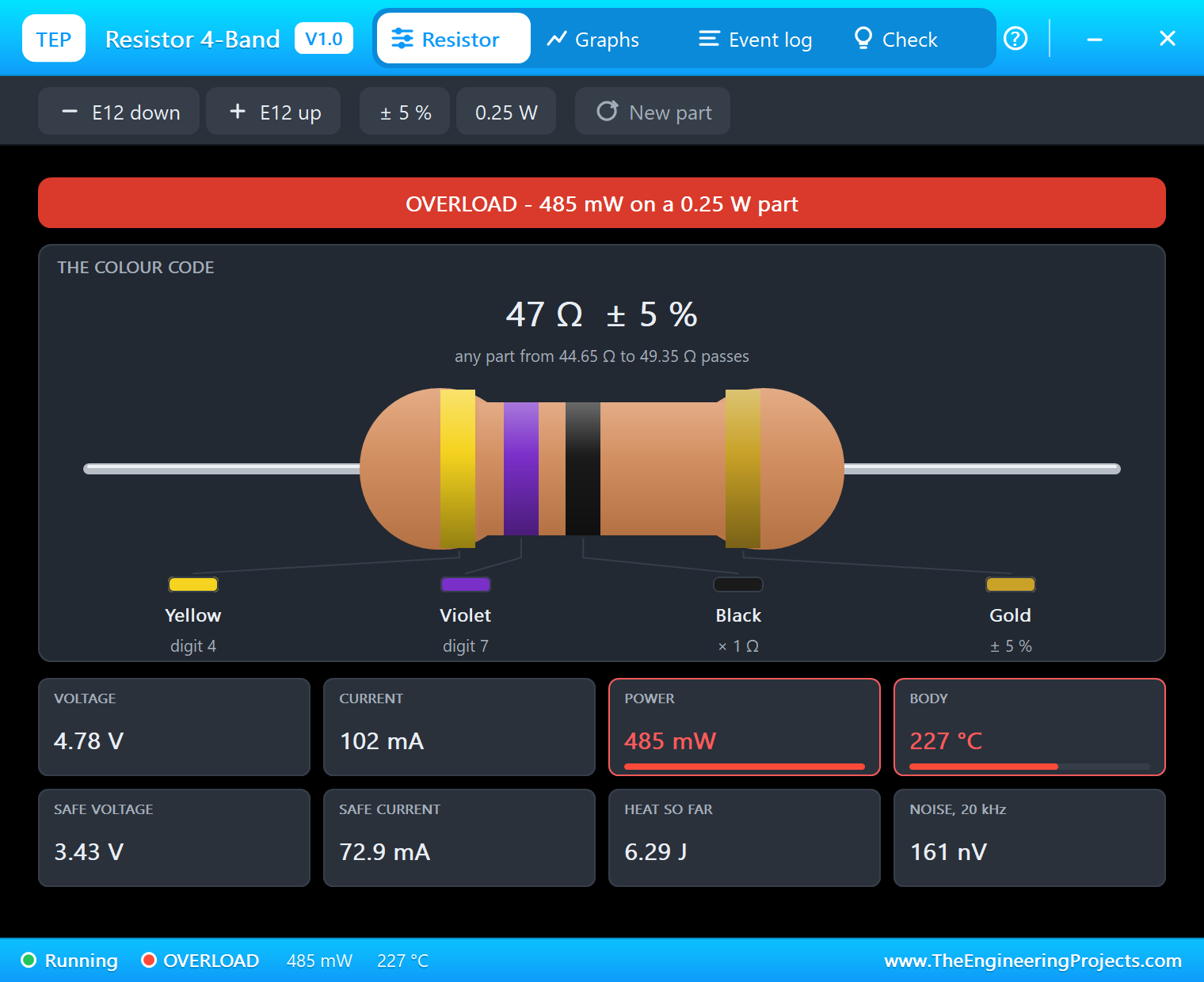
The body takes on colour as it heats up, and you can see it on the sheet. Here is the complete circuit, truly running, with R3 overloaded and the L LED on:
Burn It Out
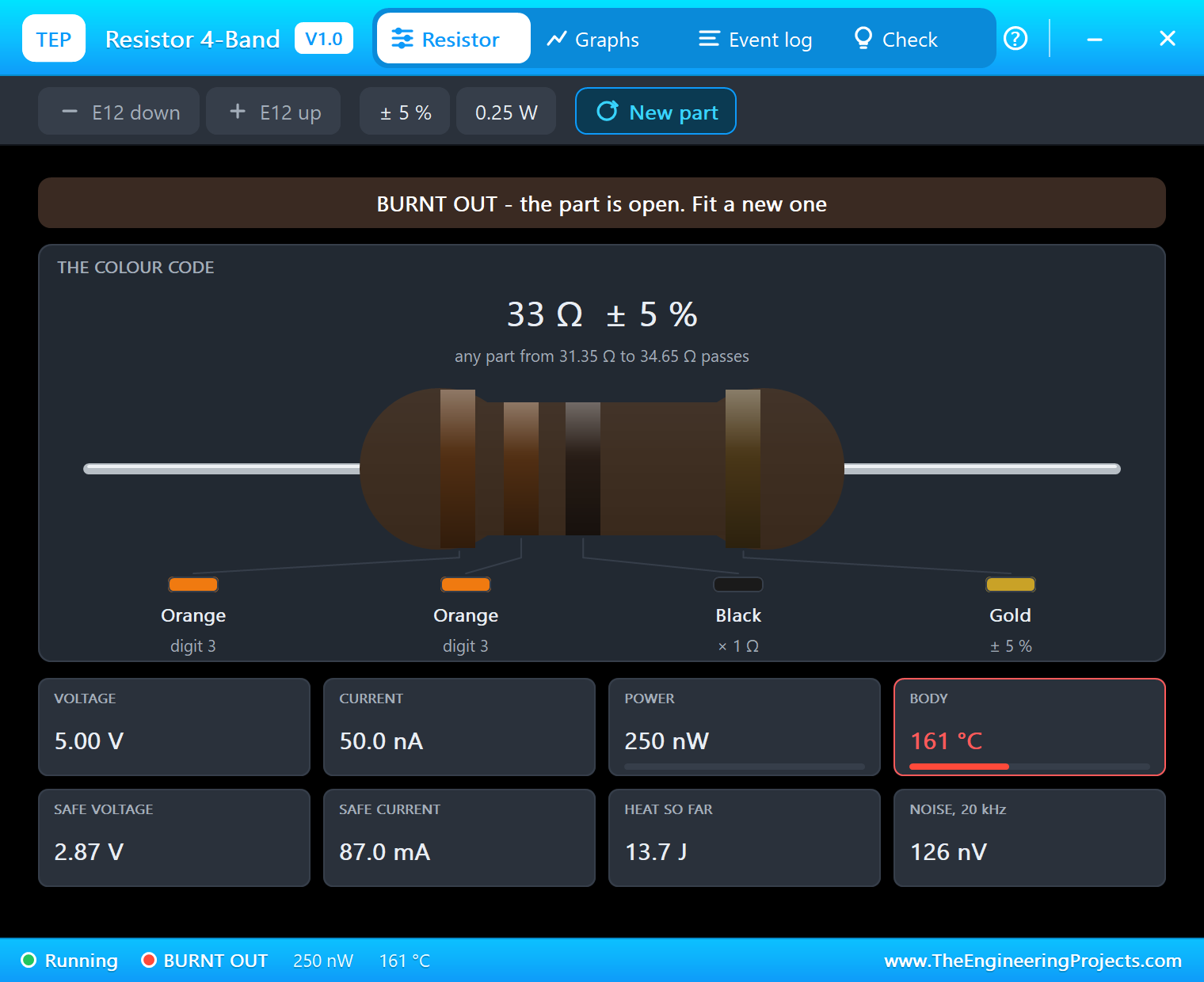
At 33 ohms R3 burns 0.666 W, more than two and a half times its rating. The body keeps climbing, and when it passes 350 C it is all over. The film breaks, the part opens and the current falls to nothing. The whole 5 V now sits across the open part, and the monitor catches it at once:
R3: 142.2 mA, 33.0 ohm, 0.666 W OVERLOAD
R2 = 5.62 kohm, nearest E12 = 5.60 kohm, bands Green Blue Red
R3 BURNT OUT: no current on A1 - the resistor is open
R2 = 5.62 kohm, nearest E12 = 5.60 kohm, bands Green Blue Red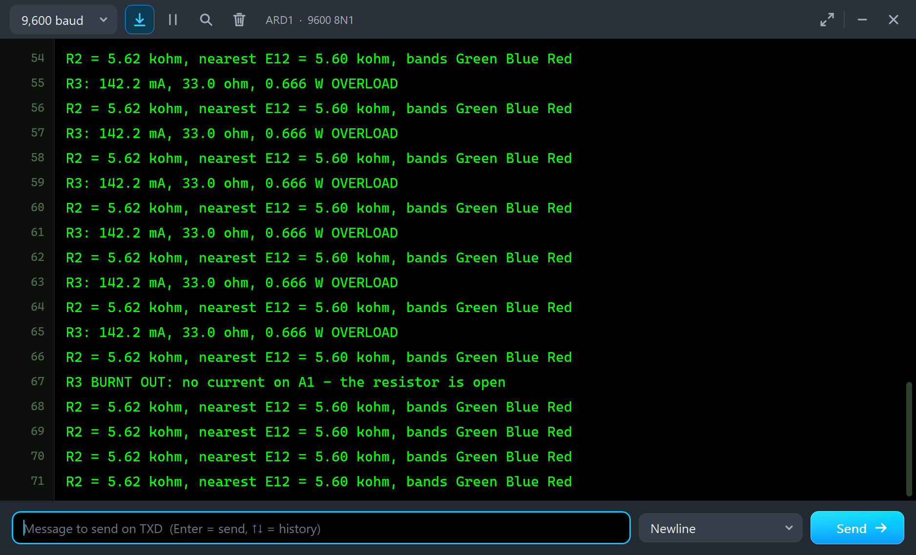
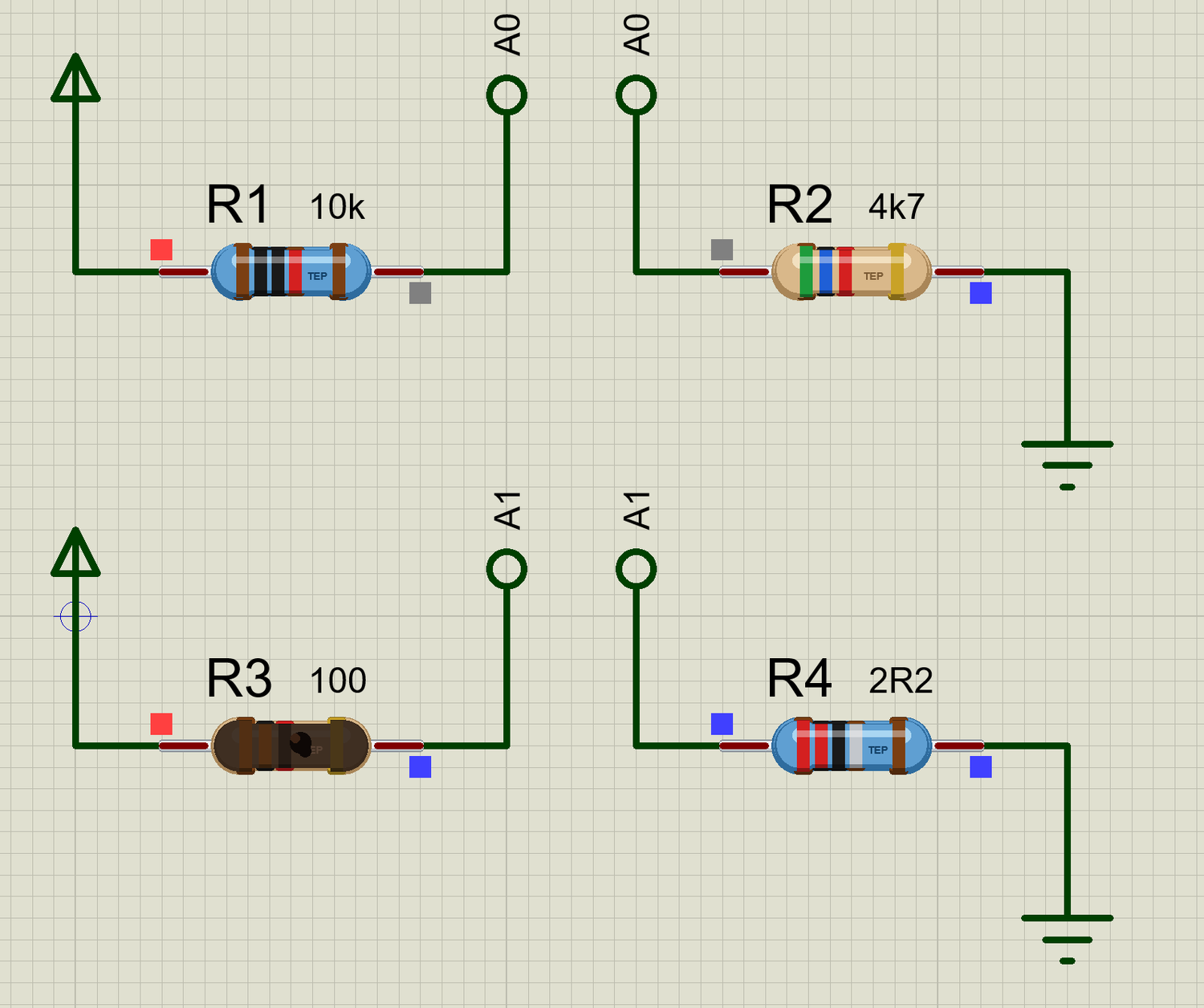
On the sheet the resistor is black and scorched:
The Graphs
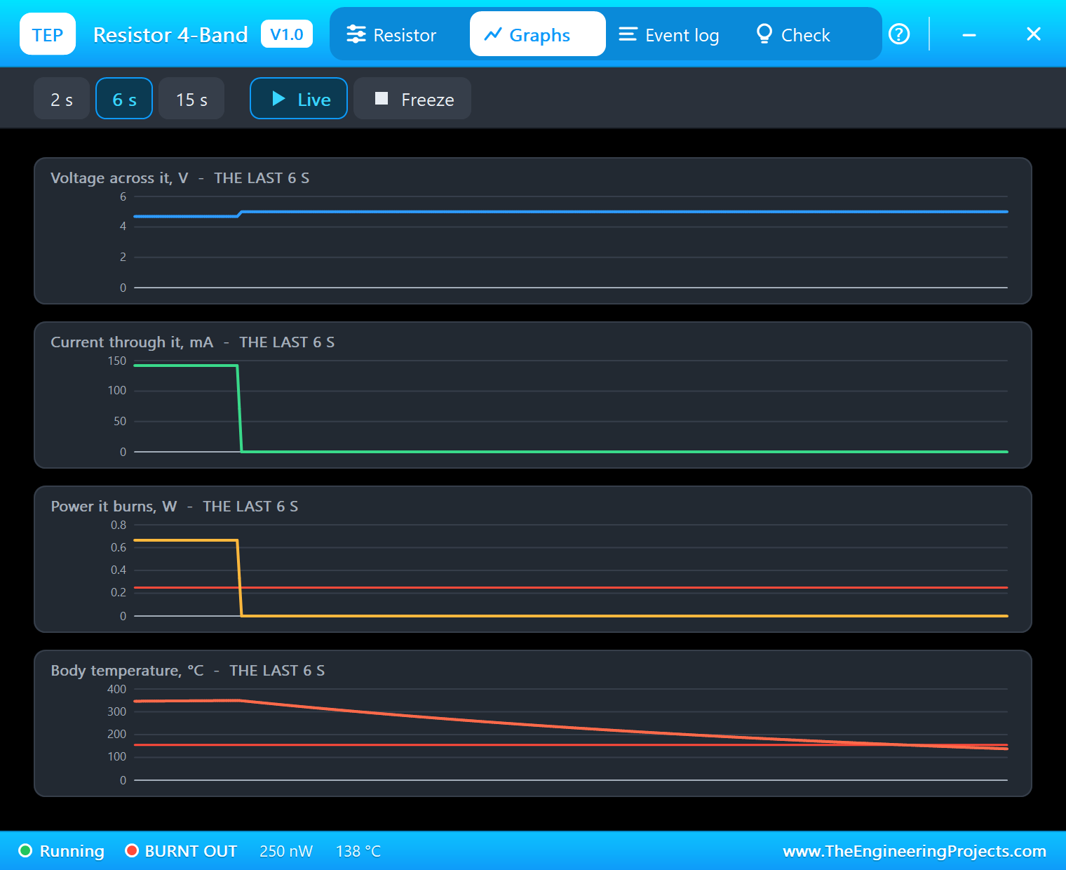
The Graphs tab shows the voltage, current, power and temperature over the last 2, 6 or 15 seconds. Here you can see the moment of failure: the current and the power drop to zero, the voltage jumps to 5 V, and the temperature starts to fall. The red lines are the rating and the 155 C limit.
The Event Log
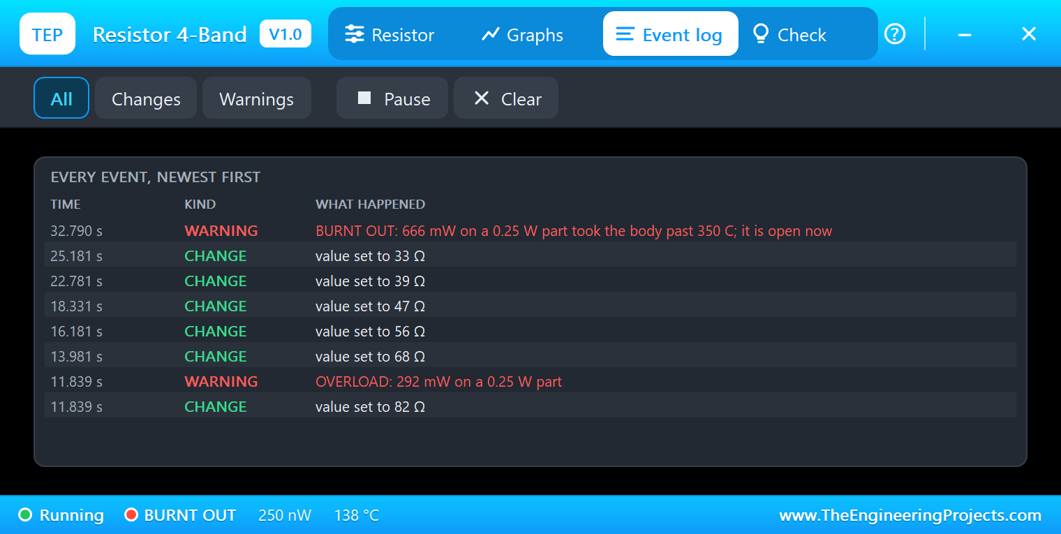
The Event log keeps the whole story, with the time of each step, so you can see exactly what you did and what it caused:
The Check Page
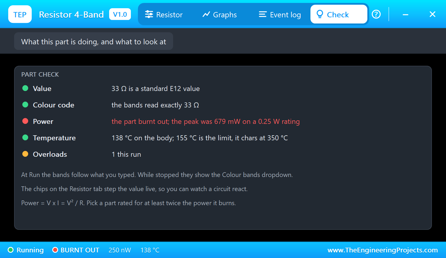
The Check page looks at the part the way an experienced engineer would. Is this a value you can buy? Do the bands show it exactly? How hard is the part working? Each row has a green, amber or red dot. It also tells you what to do about it, such as which value to pick in the dropdown so the stopped sheet matches:
Fit a New Part
A burnt part stays burnt, as it would on your bench. Press New part on the pop-up to fit a fresh one, or press Stop and Run. Be quick to step the value back up with E12 up, because at 33 ohms the new one will go the same way. Back at 100 ohms the demo reads 48.9 mA and 0.239 W again:
Try It Yourself
- Change the rating of R3 to 1 W on its pop-up, and walk it down to 33 ohms again. It survives, and that is the whole lesson of power ratings.
- Type a value that shops do not sell, such as 5k, into R2, and read the Check page.
- Swap R1 for 1k, change
R_KNOWNin the sketch to match, and see how the readings get coarser with a 4.7k unknown. - Use the tolerance chip on a 5-band part, and watch the last band change.
- Try a 0 ohm link: type 0 and look at the single black band.
Ideas to Extend the Demo
- Add an LED with its current-limiting resistor, and use the pop-up to find the smallest safe value.
- Print the bands of the multiplier for values under 10 ohms, using gold and silver.
- Show the power R3 burns on a needle: drive our Analog Panel Meter Library for Proteus from a PWM pin.
- Turn off a pin that feeds the load when the power goes over the limit, and you have an electronic fuse.
Your Own Sketches
The demo sketch is in the zip file, and you can change it in the Arduino IDE. New to Arduino? Start with our Arduino Tutorial for Beginners. Export the compiled binary, and set the UNO's PROGRAM property to the new file. Our guide on How to get the HEX file from Arduino shows you where the file ends up.
Things to Know Before Using a Real Resistor
- Do not try the burn-out carelessly: a real resistor can smoke, crack or get hot enough to burn you. Keep to low voltages and keep your fingers away.
- Read from the right end: the bunched bands come first, and the tolerance band stands a little apart.
- Colours fade and vary: if you are not sure, measure the part with a multimeter.
- Leave room in the rating: run a part below half its power rating, and it will last much longer.
- Heat changes the value: a real part drifts a little as it warms up, which our model leaves out.
Troubleshooting
- The bands on the sheet do not match the value: press Run once, or set Colour bands while stopped.
- Nothing happens when I click the part: the pop-up opens at Run only. Click the body of the resistor while the simulation runs.
- The Event log says a value is not a resistance: the Resistance box holds something else, so the part uses 1k and carries on.
- No current flows and the body is black: it burnt out. Press New part, or Stop and Run.
- The part is not simulated:
TEPRESISTOR.DLLis missing from MODELS and from the project folder.
Limitations of the Simulation
- The body temperature does not change the resistance, and the small inductance and capacitance of a real part are left out.
- The simulation uses the exact value, not a random one inside the tolerance.
- While stopped, the look comes from the 76 values in the dropdown, with a gold band on the 4-band part and a brown one on the 5-band part. At Run the bands follow everything you typed.
- The chips on the pop-up change the current run only. At Stop the part goes back to what you typed.
- Arduino is a name of Arduino; this library is not made or endorsed by Arduino or Labcenter.
- Tested in Proteus 8.5 in October 2026 (the demo as shipped). Proteus 7 is not supported.
So, that was all about the Resistor Library for Proteus. I hope it makes your circuits look a little more real, and helps you learn the colour code and power ratings without burning a single part on your bench. If you have any questions, ask in the comments and I will help you out. Till the next tutorial, take care and have fun!