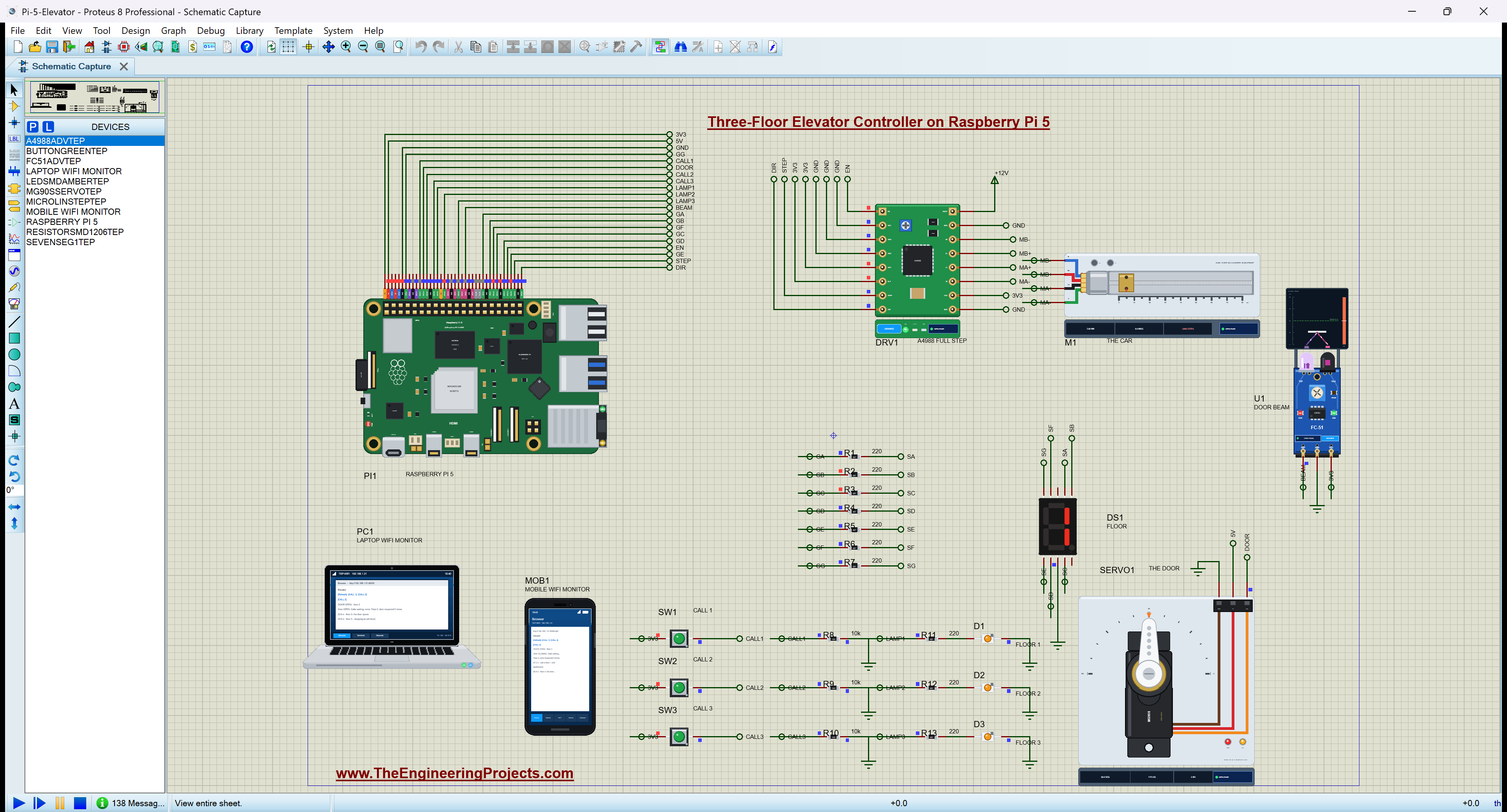
Hello friends, I hope you all are doing great. Today, I am going to share the Three-Floor Elevator Controller on Raspberry Pi 5 - Proteus Simulation, the fifty-second project of our IoT Projects series. If you have searched for a Raspberry Pi elevator project, an elevator controller in Python, or a Proteus simulation of a lift with call buttons, a floor display and a safe door, here is a complete one. A Raspberry Pi 5 runs a scale-model three-floor elevator: the car rides on a micro linear stepper's lead screw, it finds its own position at power-up, it answers the call buttons in the order real elevators do, it shows the floor on a 7-segment digit, it opens and closes the door with a servo, and it opens the door again when something steps into the doorway, all with a web dashboard on a laptop or a phone.
An elevator looks like a box on a rope, but its controller makes a long series of decisions every second: where the car is, which calls are waiting, which way to go, when to stop, when the door may close. In this tutorial, we will go through the circuit, see how a lead screw turns a stepper's steps into millimetres, why an open-loop stepper must find home at power-up and how it can do it without a switch, set the A4988's current for a tiny motor, look at the SCAN algorithm that real elevators use to serve calls, drive a servo door with a safety beam, walk through the Python program, and then run the simulation: homing, a call to floor 3 with a call to floor 2 picked up on the way, a call from the phone, and a door that refuses to close on someone. At the end, you can download the project with the program and every library file.
NOTICE: Our team has put a lot of effort into this project: the circuit, the code and every part in the simulation are our own work, and you get them all free. Your feedback is the fuel that keeps us going, so please tell us what you think in the comments below. And if our free projects help you, you can buy us a coffee. So, let's get started with the Raspberry Pi 5 elevator in Proteus simulation:
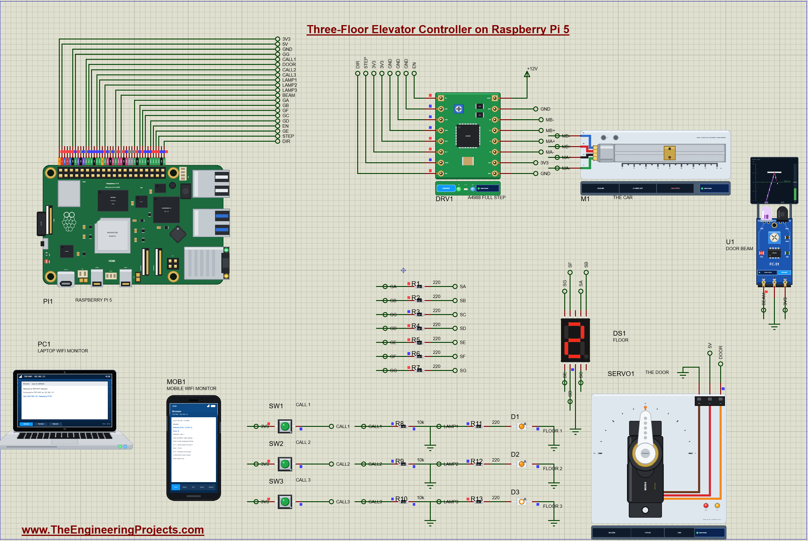
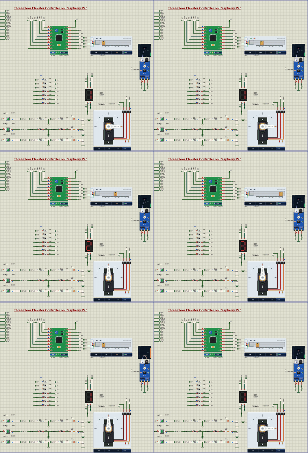
What Does This Elevator Controller Do?
- Finds its own position: at power-up the car drives down into the bottom stop, then up to floor 1.
- Moves by the millimetre: a micro linear stepper on an A4988, 40 full steps a millimetre; floors 1, 2 and 3 at 5, 40 and 75 mm.
- Answers calls like a real elevator: the SCAN algorithm keeps going while there are calls ahead and stops at each called floor on the way.
- Shows what it is doing: a call lamp at each button, the floor on a 7-segment digit.
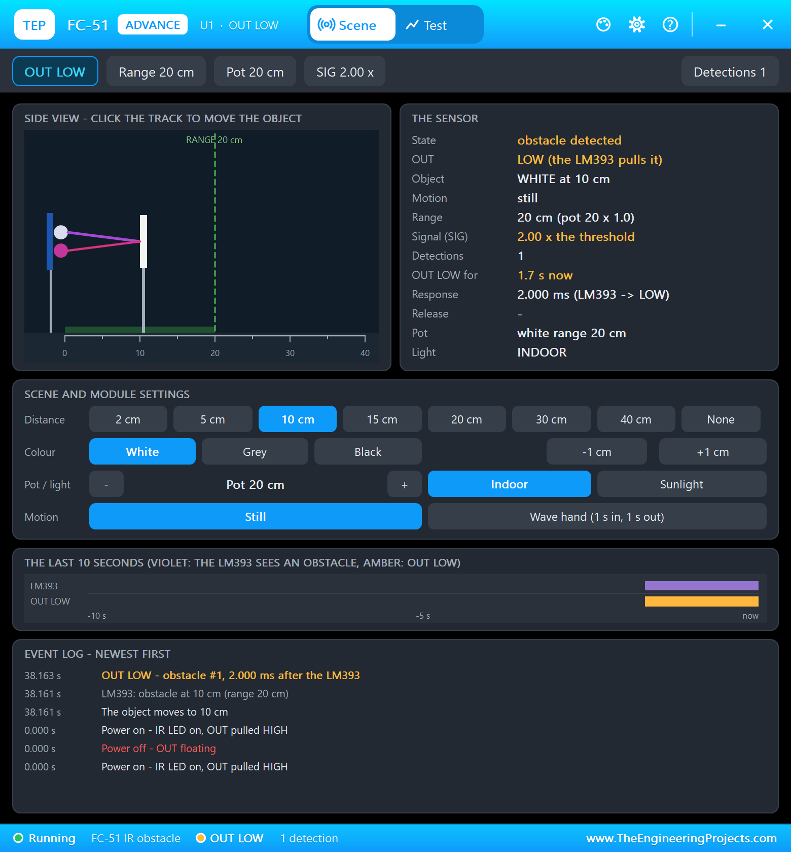
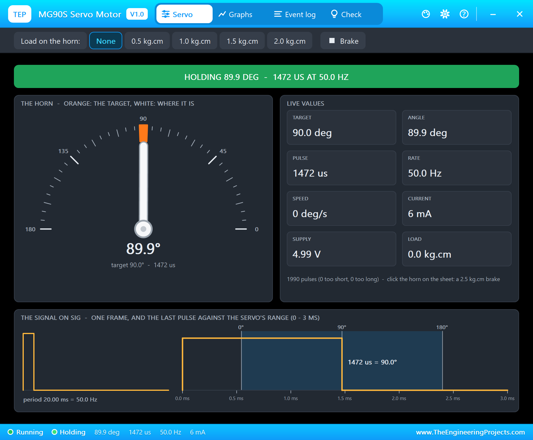
- A safe door: an MG90S servo opens the door for 3 seconds; an FC-51 IR beam keeps it open while someone stands in the doorway and opens it again if they step in while it closes.
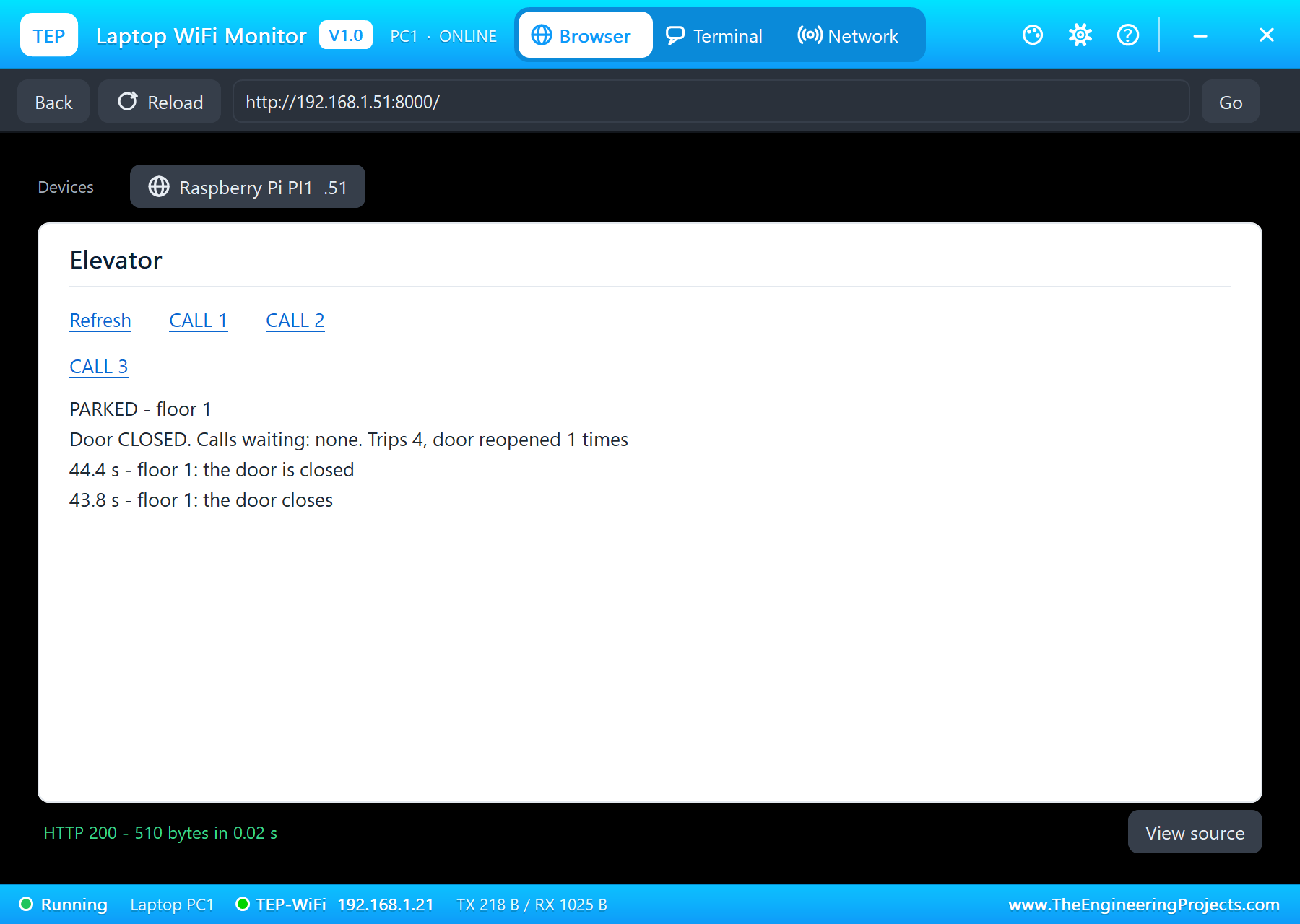
- A web dashboard: the state, the floor, the door and the calls waiting, with CALL 1, 2 and 3, on a laptop or a phone.
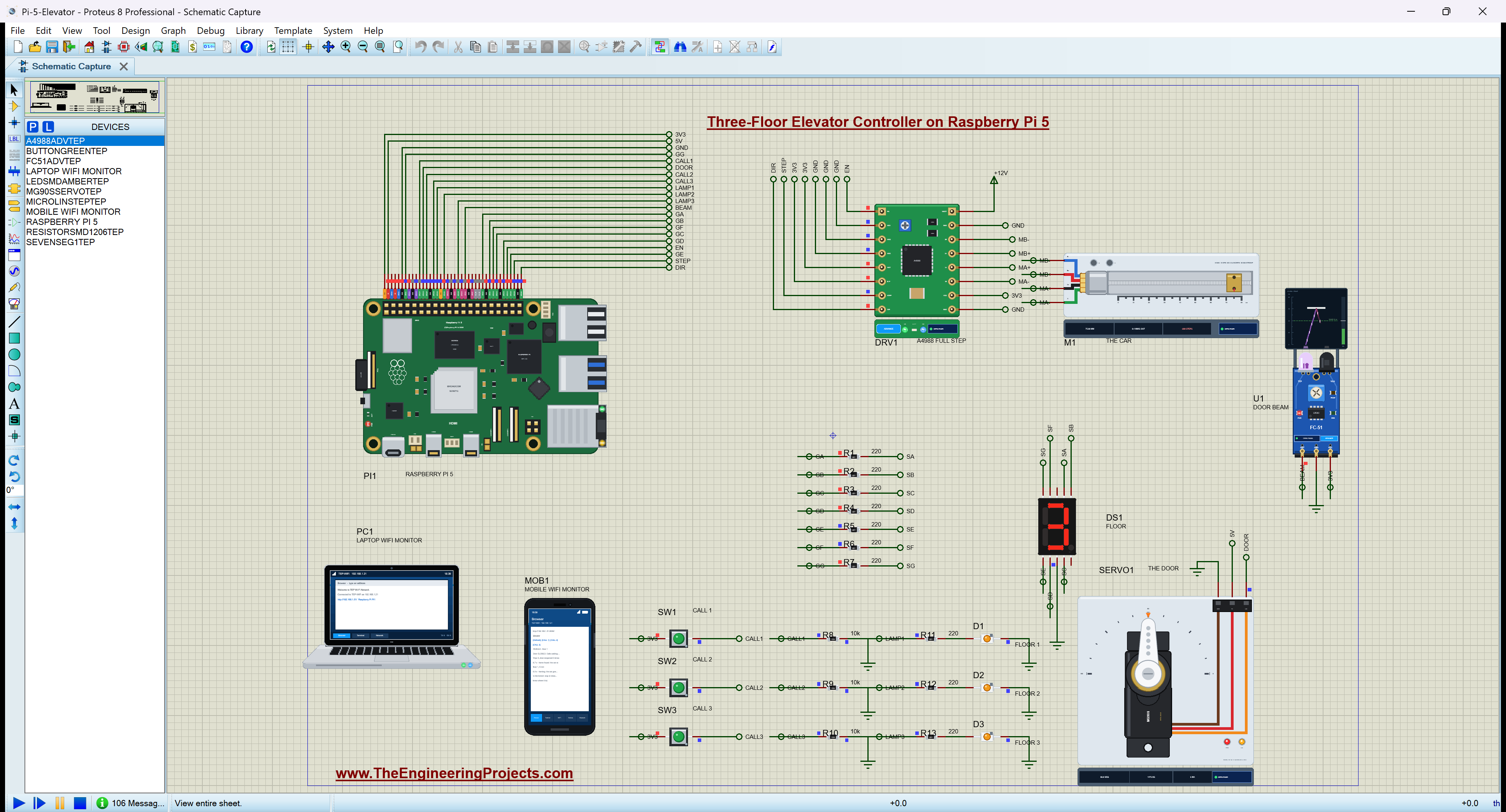
It is a great project for learning stepper motors and lead screws, homing, a real scheduling algorithm, servo control, a safety interlock and threads in Python. In the simulation, the linear stepper's pop-up shows the slider on its screw, its position in millimetres and every step lost; the A4988's pop-up shows the coil currents; the servo's pop-up shows the door angle; the FC-51's pop-up lets you put an object in the beam; and the call lamps and the digit light on the sheet.
Components Used in the Proteus Simulation
All the parts come from our Proteus libraries, each with its own tutorial. The project zip at the end includes every LIB and DLL file and the TEPPi Python runtime.
| Part | Proteus device | Library post | Connection |
|---|---|---|---|
| Raspberry Pi 5 | RASPBERRY PI 5 | Raspberry Pi 5 Library for Proteus | PI1, Ethernet 192.168.1.51 |
| A4988 stepper driver | A4988ADVTEP | A4988 / DRV8825 Stepper Driver Library | DRV1, STEP GPIO20, DIR GPIO21, EN GPIO16 |
| Micro linear stepper (the car) | MICROLINSTEPTEP | Micro Linear Stepper Motor Library | M1, 80 mm stroke, START 30 mm |
| 7-segment digit | SEVENSEG1TEP | 7-Segment Display Library | DS1, the floor |
| SMD resistors 1206 | RESISTORSMD1206TEP | SMD Resistor Library | R1 - R7, R11 - R13 220 ohm; R8 - R10 10 kohm |
| Push buttons | BUTTONGREENTEP | Push Button Library | SW1 - SW3, the calls, GPIO17 / 27 / 22 |
| SMD LEDs (amber) | LEDSMDAMBERTEP | SMD LED Library | D1 - D3, the call lamps, GPIO23 / 24 / 25 |
| MG90S servo (the door) | MG90SSERVOTEP | MG90S Servo Motor Library | SERVO1, GPIO18 |
| IR obstacle sensor FC-51 | FC51ADVTEP | IR Obstacle Sensor FC-51 Library | U1, the door beam, GPIO8 |
| Laptop WiFi Monitor | LAPTOP WIFI MONITOR | Laptop WiFi Monitor | PC1 |
| Mobile WiFi Monitor | MOBILE WIFI MONITOR | Mobile WiFi Monitor | MOB1 |
The car is the slider of a 15 mm micro linear stepper, the kind that moves camera lenses and small stages: a stepper with an M3 lead screw through it and a nut on the screw. It is a compact stand-in for an elevator's hoist, and all the resistors are tiny 1206 SMD chips.
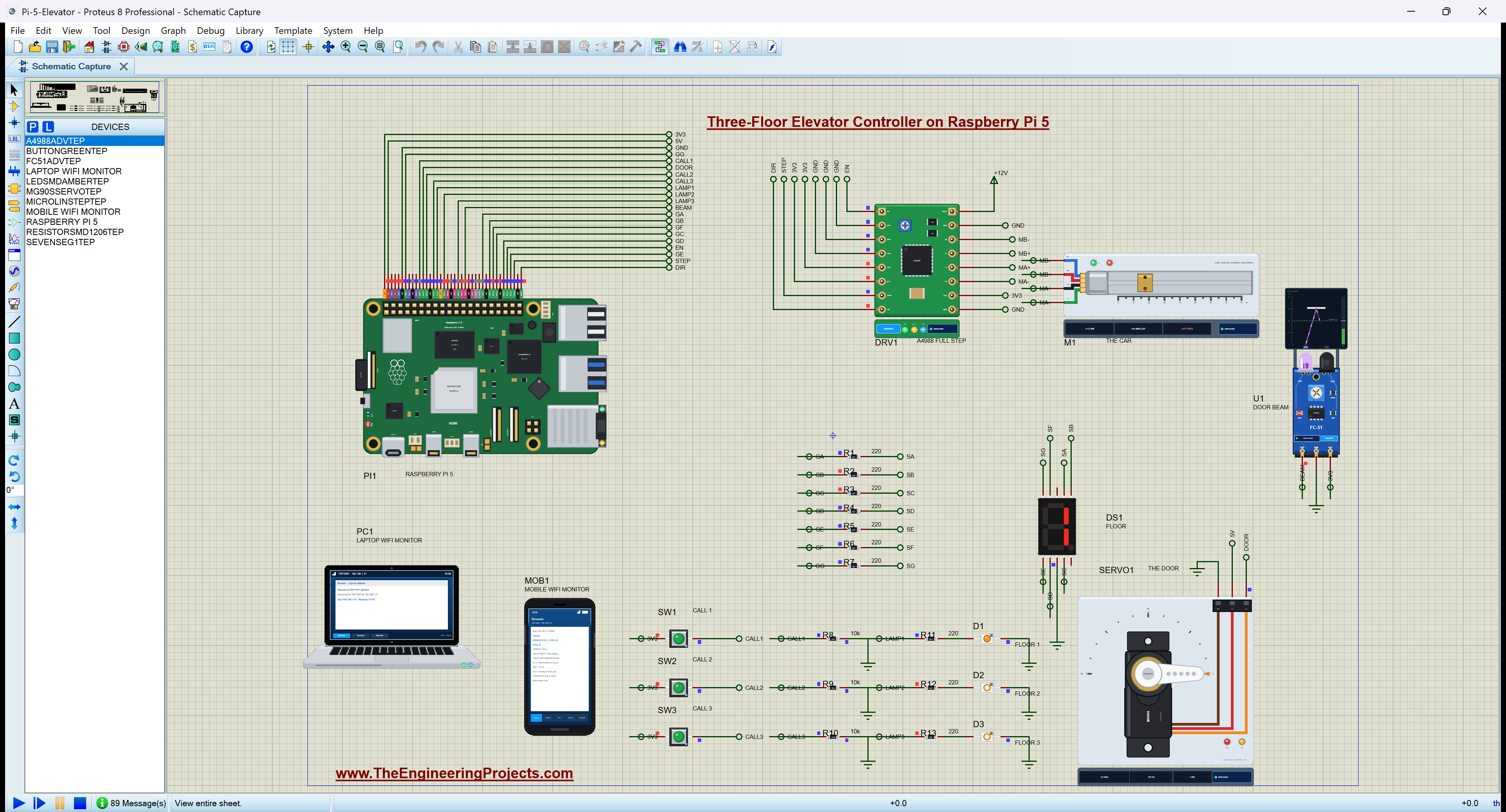
Proteus Simulation of the Elevator: the Circuit
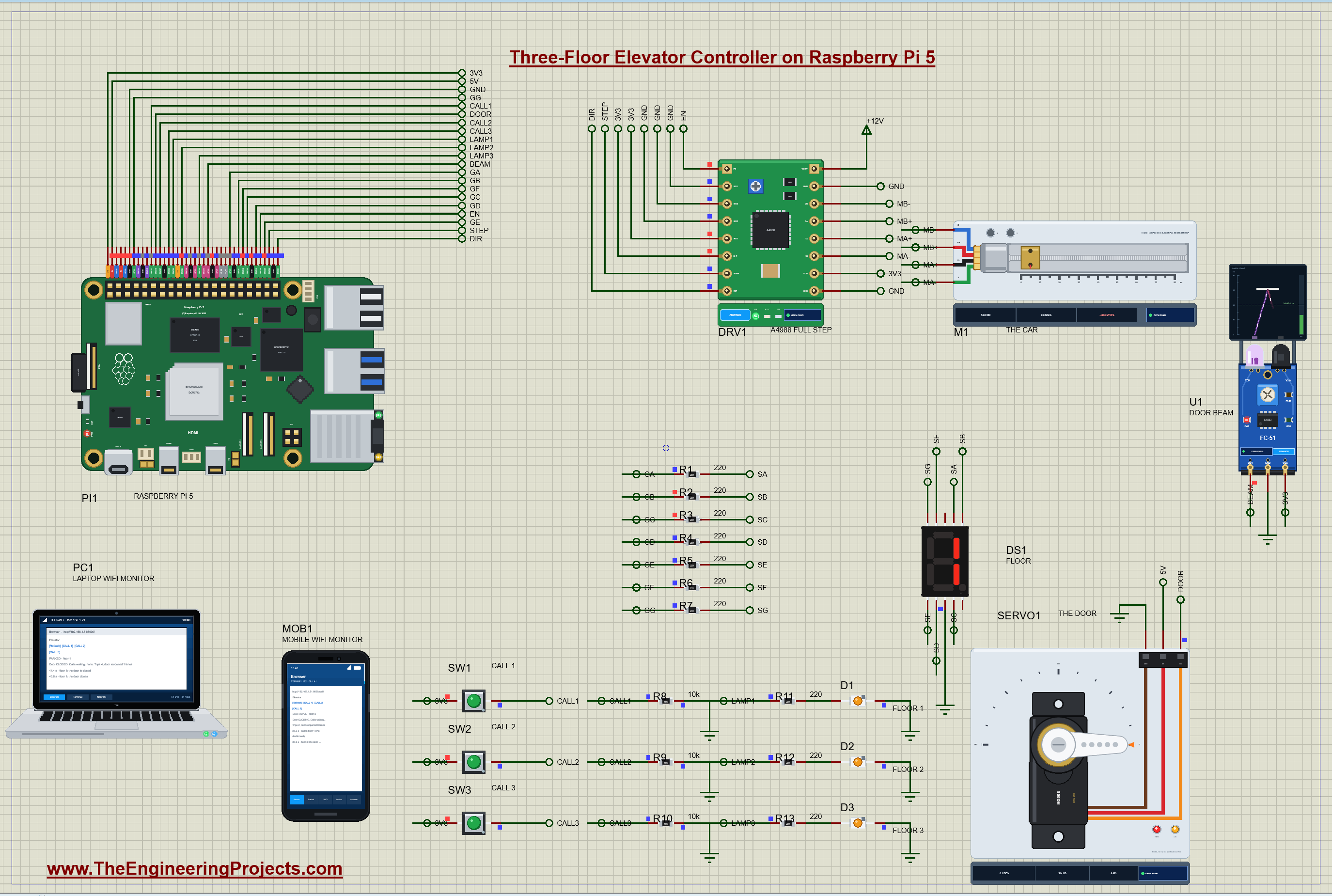
| Part | Pins | Raspberry Pi 5 / other |
|---|---|---|
| DRV1 A4988 | STEP / DIR / EN | GPIO20 (pin 38) / GPIO21 (pin 40) / GPIO16 (pin 36) |
| DRV1 A4988 | MS1 MS2 MS3 / RST SLP VDD / VMOT | GND (full steps) / 3V3 / +12V |
| M1 linear stepper | A+ A- B+ B- | DRV1 1A 1B 2A 2B |
| SW1 - SW3 | 1 / 2 | 3V3 / GPIO17, 27, 22 with R8 - R10 10 kohm to GND |
| D1 - D3 | A through R11 - R13 / K | GPIO23, 24, 25 / GND |
| DS1 digit | a - g / COM | GPIO5, 6, 13, 19, 26, 12, 4 through R1 - R7 / GND |
| SERVO1 | SIG / V+ / GND | GPIO18 (pin 12) / 5V / GND |
| U1 FC-51 | OUT / VCC / GND | GPIO8 (pin 24) / 3V3 / GND |
The A4988 takes its logic from the Pi's 3.3 V and its motor supply from 12 V; with MS1 to MS3 tied low it makes full steps. Each call button switches 3.3 V to its input, held low by a 10 kohm pull-down until it is pressed, and each call lamp is an SMD LED with its own resistor. The servo needs 5 V for its motor but takes the Pi's 3.3 V pulses on its signal wire. The FC-51 has its own pull-up on OUT and pulls it low when its IR LED's light comes back from an object.
How the Elevator Works
From Steps to Millimetres: the Lead Screw
The micro stepper makes 20 full steps a turn, 18 degrees each, and its M3 lead screw moves the nut 0.5 mm a turn. One step is 0.5 / 20 = 0.025 mm, so 40 steps make a millimetre. The floors are at 5, 40 and 75 mm, clear of the two stops at 0 and 80 mm.
Worked example: from floor 1 to floor 2 is 40 - 5 = 35 mm, which is 35 x 40 = 1400 steps. At 400 steps a second that takes 1400 / 400 = 3.5 s, a speed of 10 mm/s. A real elevator moves at 1 to 2 metres a second; this model is a hundred times slower, and a hundred times smaller.
Open Loop, So It Must Find Home
A stepper has no sensor: the controller knows where the car is only by counting the steps it sent. That works as long as no step is ever lost, but at power-up the count starts from nothing: the car may be anywhere, left there by a power cut. So the program homes first. It drives the car down by 82 mm worth of steps, more than the whole stroke. Wherever the car started, it reaches the bottom stop on the way, and the steps left over are simply lost against the stop: the field turns but the slider cannot follow. Now the car is at exactly 0 mm, and the count can begin. Many 3D printers home this way, without a switch; a real elevator uses limit switches and floor sensors as well, because a stall is hard on a big machine.
Between moves the driver is switched off. A lead screw this fine cannot be turned backwards by the load on its nut, so it holds the car by itself, with no holding current: the motor and the driver stay cool, and the 12 V supply idles.
Setting the A4988 for a Tiny Motor
The micro stepper's coils are 15 ohm and rated about 0.33 A. The A4988 is a chopper: it holds each coil's current at a limit set by the voltage VREF, I = VREF / (8 x Rsense). With the board's 0.068 ohm sense resistors, 0.33 A needs VREF = 0.33 x 8 x 0.068 = 0.18 V, and that is the VREF of this design. Left at a typical 1 A setting, the A4988 would push the full 12 / 15 = 0.8 A through the little coils and cook them.
The SCAN Algorithm: Answering Calls Fairly
Suppose the car is at floor 1, someone calls it to floor 3, and while it is on the way, someone on floor 2 presses their button. A first-come, first-served controller would go to 3, then come back down to 2. Real elevators use SCAN, also called the elevator algorithm: the car keeps going in its direction while there are calls ahead, stopping at each called floor as it passes, and only turns round when there is nothing more ahead. So the car stops at 2 on its way up, then goes on to 3. SCAN never leaves a call waiting for long, and it saves needless trips; the same idea schedules the heads of hard disks.
A Door That Will Not Close on You
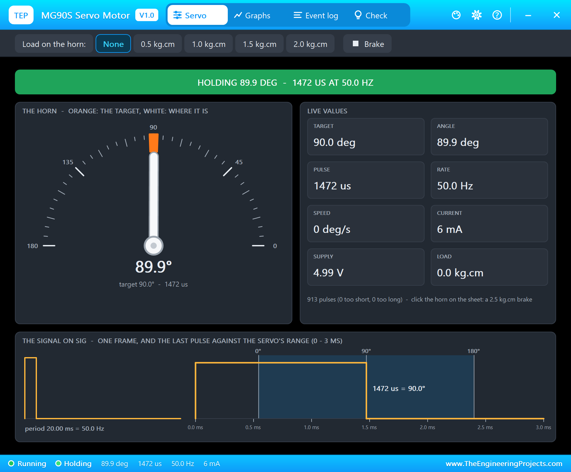
The door is an MG90S servo: a 50 Hz pulse of 544 us puts its horn at 0 degrees (closed) and 2400 us at 180; the program uses 90 degrees for open. Real elevator doors have a light curtain across the opening, and this one has an FC-51 IR sensor looking across the doorway. While its beam is broken, the door stays open; and if something steps into the doorway while the door is closing, the program stops the close and opens the door again at once. That is the safety rule of every lift: a closing door must never trap anyone.
Call Buttons and Lamps
Each call button is read every 20 ms; a press counts when the input is still high 30 ms after it went high, so contact bounce makes one call, not ten. The call lamp lights at once, telling the person the call was accepted, and goes off when the car arrives and the door opens. A call at the floor where the car already stands simply opens the door again.
Three Threads
The program does three things at once. The inputs thread watches the buttons; the controller thread homes the car and then runs the elevator, one floor at a time, so a call made while the car is moving can still stop it at the next floor; and the main thread serves the dashboard. A call from a button and a call from the dashboard go through the same function, and a lock keeps the shared state consistent.
The Python Code Explained
The whole program is included in the download. It needs no extra library: lgpio for the GPIO, the step pulses and the servo, threading and http.server for the dashboard. The geometry and the speed are at the top:
FLOOR_MM = [5.0, 40.0, 75.0]                                     # floors 1, 2, 3 on the 80 mm lead screw
STEPS_MM = 40                                                    # 0.5 mm a turn, 20 full steps a turn
RATE = 400                                                       # full steps a second: 10 mm/s, slow enough never to lose a step
Exact Steps
A move is a hardware square wave on STEP, stopped half a period after the last rising edge, so the count is exact, as in our Raspberry Pi 5 Pill Dispenser with A4988 Stepper:
    lgpio.tx_pwm(chip, STEP, RATE, 50)
    time.sleep((n - 0.5) / RATE)
    lgpio.tx_pwm(chip, STEP, 0, 0)
lgpio.gpio_write(chip, EN, 1) # off again: the lead screw holds the car by itselfHoming
steps(int(82 * STEPS_MM), up=False) # 82 mm down: whatever is left over is lost against the stopSCAN
The next direction comes from the calls above and below the car:
above = any(calls[floor + 1:]); below = any(calls[:floor])A button press counts only if the input is still high 30 ms after it went high:
            if b and not last[k]:
                time.sleep(0.03)
                if lgpio.gpio_read(chip, g):
                    call(k, 'the button')
A call is ignored only if it is already waiting, or if the door is open at that floor:
if s['calls'][floor] or (s['floor'] == floor and s['state'] == 'DOOR OPEN'):The Door
lgpio.tx_servo(chip, DOOR, int(544 + (2400 - 544) * angle / 180), 50) # MG90S: 544 - 2400 us for 0 - 180 degWhile the door is open, a broken beam restarts its wait; while it closes, a broken beam opens it again:
end = time.monotonic() + DOOR_OPEN_S # someone in the doorway: wait for them door(90); event('floor %d: something in the doorway - the door opens again' % (floor + 1))The pages are / (the dashboard), /call1, /call2 and /call3 (a call from the dashboard) and /data (everything as JSON). The dashboard puts its links first and stays short, because the WiFi Monitors show one screen of a page. The Pi's terminal prints every event with its time.
How to Run the Proteus Simulation
- Download the project zip below and install the library files and the TEPPi folder (the steps are under the download button).
- Open Pi-5-Elevator.pdsprj from the Proteus Simulation folder. Keep elevator.py and the DLL files next to it.
- Press Play. The car homes down to the stop and comes back to floor 1; the digit shows 1.
- Press a call button (its cap, or Press on its pop-up): its lamp lights and the car comes.
- On the FC-51's pop-up choose 10 cm while the door closes: the door opens again.
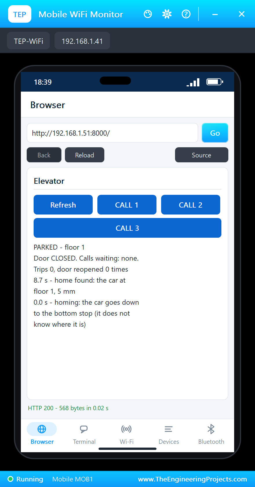
- Open the Laptop or the Mobile WiFi Monitor and press Go for the dashboard, with CALL 1, 2 and 3.
Simulation Results: the Elevator in Proteus
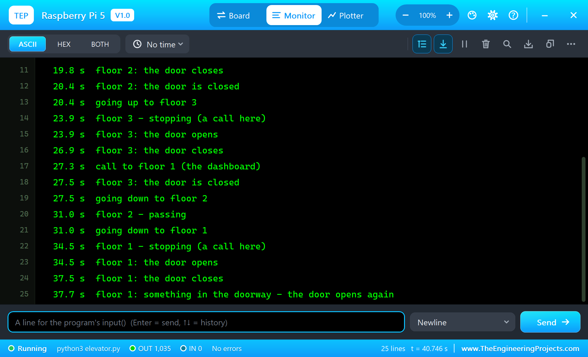
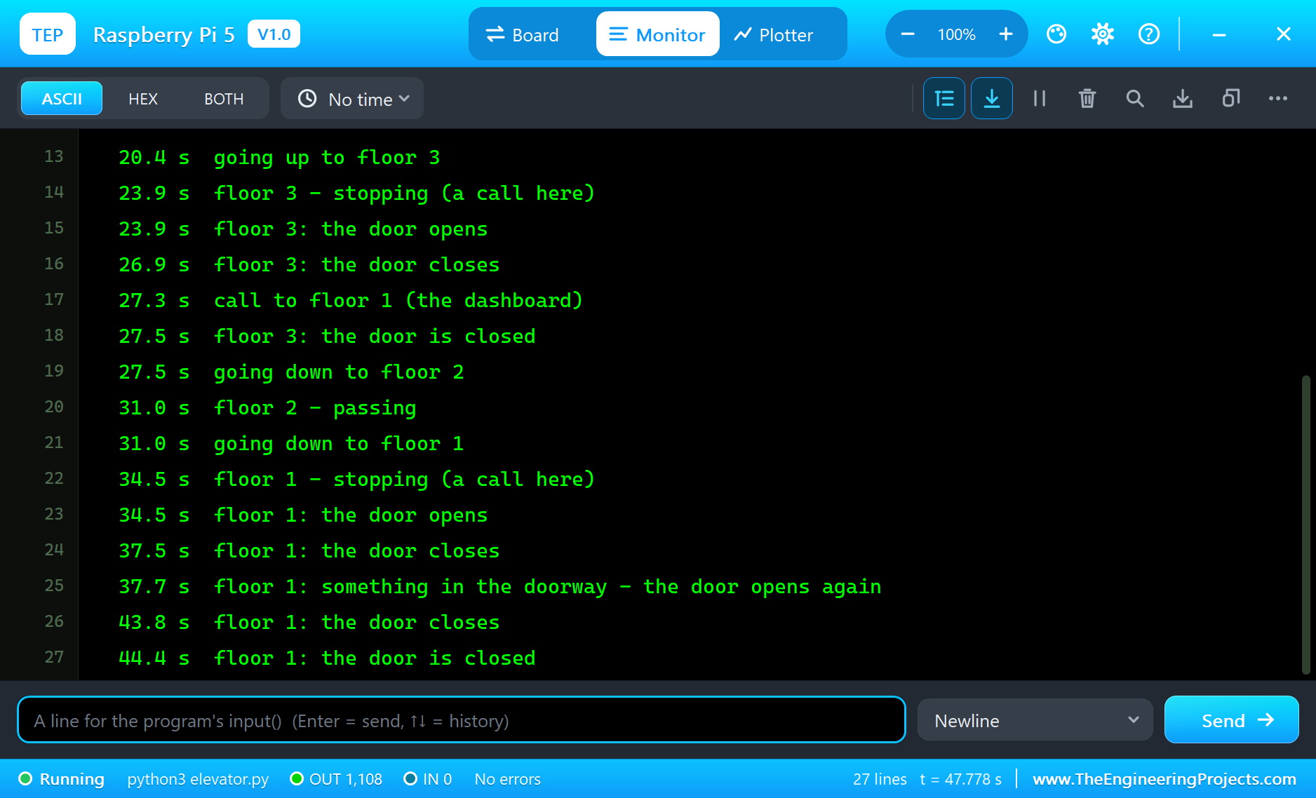
Here is the run that made the screenshots of this tutorial, 48 seconds of simulation: homing, a call to floor 3 with a call to floor 2 picked up on the way, a call from the phone, and a door that would not close on someone. The times are the program's own clock, as it printed them on the Pi's terminal; the parts' numbers come from their pop-ups.
Homing
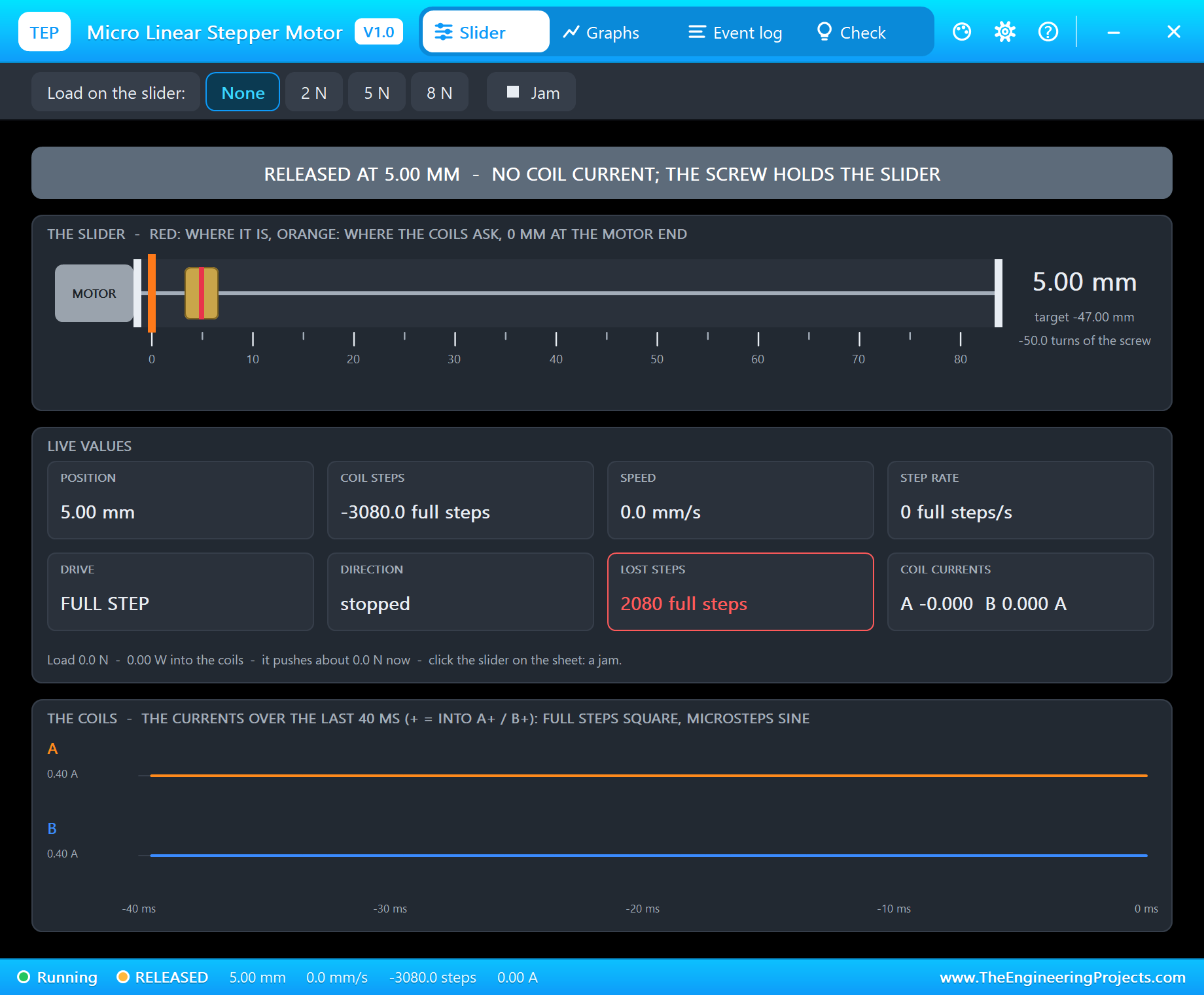
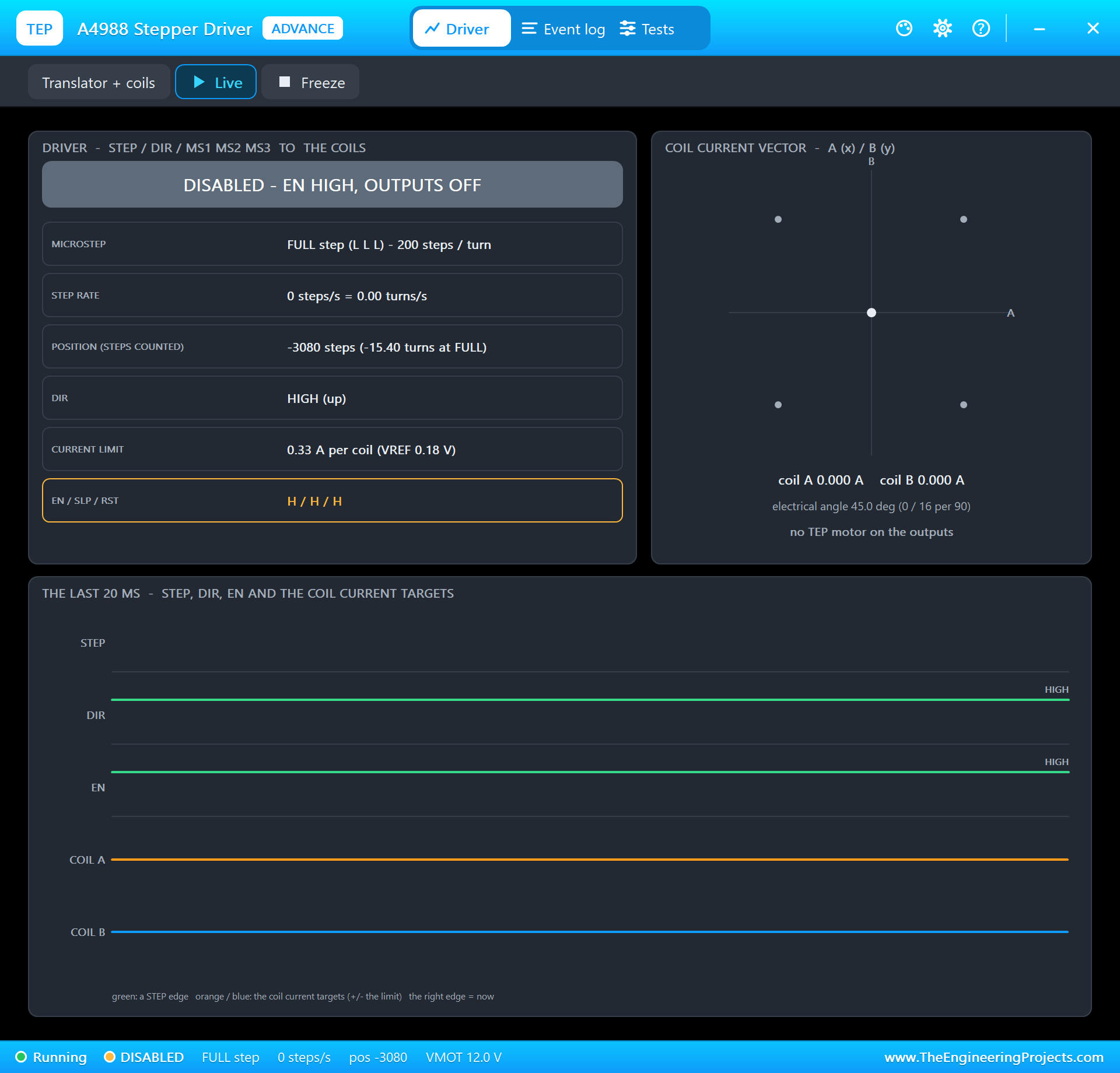
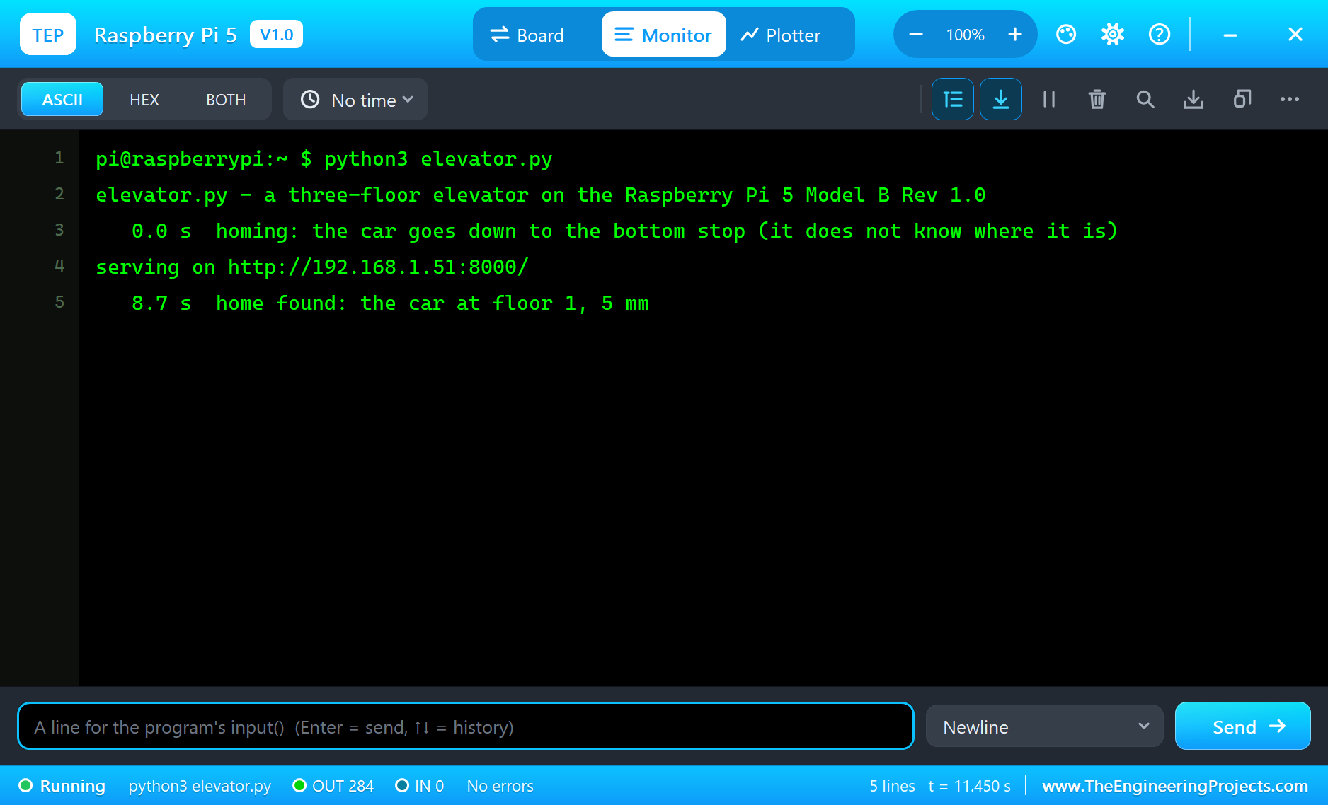
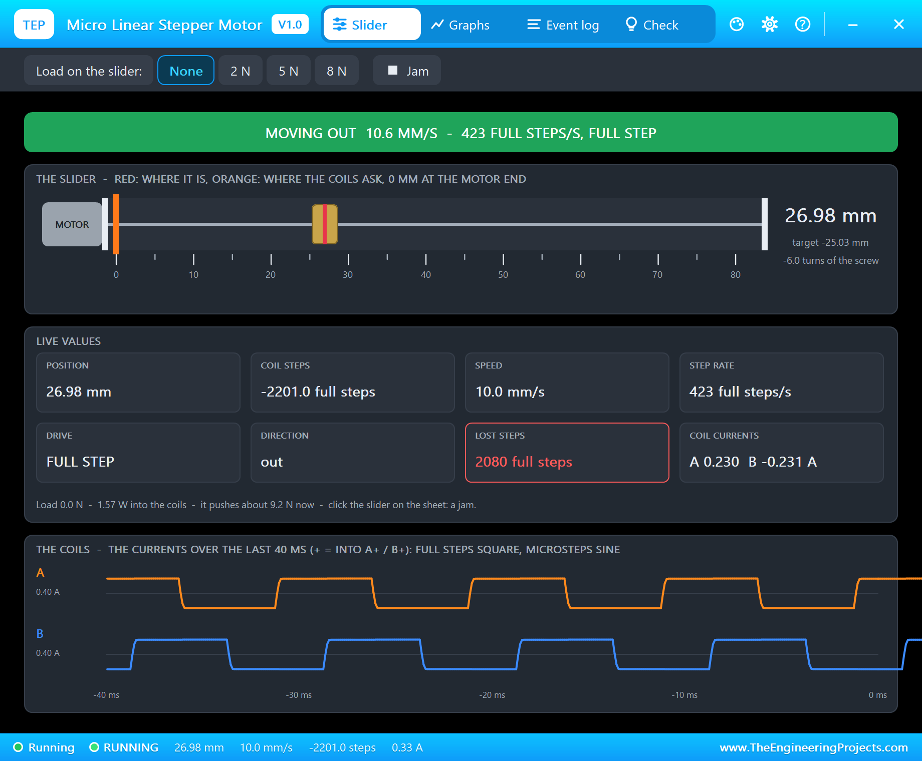
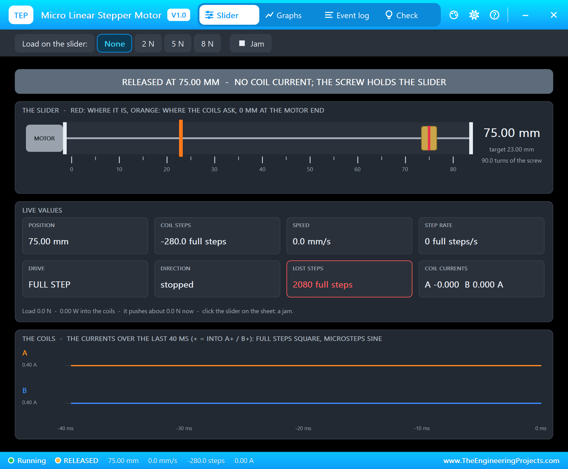
The car starts at 30 mm, as if a power cut had stopped it between floors. "homing: the car goes down to the bottom stop": the program sends 82 mm worth of steps down. After 30 mm the slider meets the stop, and the rest of the steps are lost there; the linear stepper's pop-up counts them, 2080 full steps, and flags them in red, because a lost step is normally a fault - here it is the whole point. Then 5 mm up, and at 8.7 s "home found: the car at floor 1, 5 mm". The A4988's pop-up shows the 0.33 A limit set by VREF = 0.18 V and the driver disabled again after the move.
CALL 3, and CALL 2 on the Way: SCAN
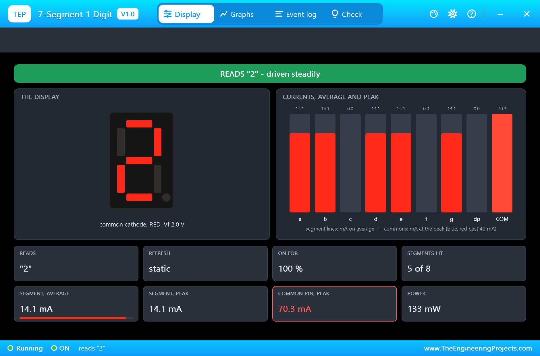
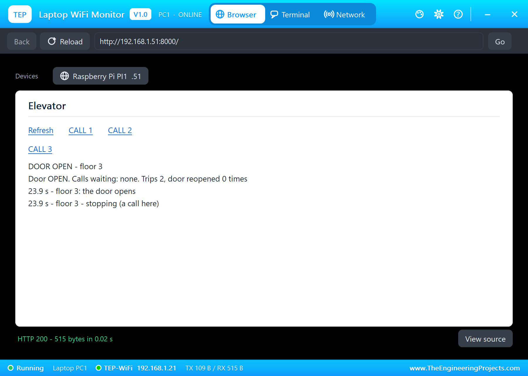
At 13.2 s CALL 3 is pressed: its lamp lights and the car sets off, "going up to floor 2". At 14.1 s, while the car is between floors 1 and 2, CALL 2 is pressed too. The car is going up and floor 2 is ahead, so SCAN stops there first: at 16.8 s "floor 2 - stopping (a call here)", the door opens and the digit shows 2. On the way, the pop-up shows the car moving at 10.6 mm/s, 423 full steps a second, with square coil currents, full steps. After 3 seconds the door closes, and the car goes on to floor 3, arriving at 23.9 s at 75.00 mm, where the pop-up shows "released - no coil current; the screw holds the slider".
CALL 1 from the Phone, and the Door Beam
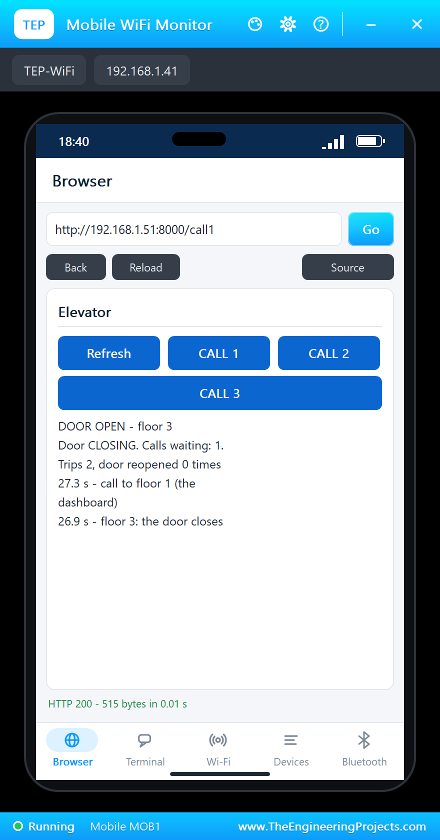
At 27.3 s, while the door at floor 3 is closing, CALL 1 comes from the phone. When the door has closed, the car goes down, "floor 2 - passing" at 31.0 s, as nobody called it there, and at 34.5 s it stops at floor 1 and opens the door. At 37.5 s the door starts to close, and just then something steps into the doorway: the FC-51 sees an object at 10 cm, its OUT goes low, and at 37.7 s the program reports "something in the doorway - the door opens again". The door waits; when the doorway is clear, it waits its 3 seconds and closes at 44.4 s. The dashboard counts 4 trips and 1 reopen.
The Numbers of the Run
| What | Result |
|---|---|
| Homing | from 30 mm: 2080 steps lost at the stop; floor 1 (5 mm) at 8.7 s |
| Speed | 10.6 mm/s, 423 full steps a second; 3.5 s a floor |
| SCAN | CALL 3 at 13.2 s, CALL 2 at 14.1 s: floor 2 at 16.8 s, then floor 3 at 23.9 s |
| Phone | CALL 1 at 27.3 s: floor 2 passed at 31.0 s, floor 1 at 34.5 s |
| Door beam | blocked while closing at 37.5 s: opened again at 37.7 s; closed at 44.4 s |
| Simulation | 48 s of simulation, 4 trips, 1 reopen |
Download the Project Files
Click the button below to download Three-Floor-Elevator-Controller-Raspberry-Pi-5-Proteus-Simulation-v1.0.zip (about 15.3 MB, without the source code of the models):
Three-Floor Elevator Controller on Raspberry Pi 5 in Proteus Simulation V1.0- Proteus Simulation: Pi-5-Elevator.pdsprj, the program elevator.py and copies of the models.
- Python Code: elevator.py, the complete program.
- Proteus Library Files: the LIB files of the Raspberry Pi 5, the A4988, the micro linear stepper, the 7-segment digit, the SMD resistors and LEDs, the push button, the MG90S, the FC-51 and the two WiFi Monitors.
- Proteus Model Files: the DLL models and the TEPPi folder, the Python 3.11 and the runtime that the Pi board runs.
- README.txt: the installation steps, the properties, the test results and the links to every library post.
No Proteus yet? Read How to Download and Install Proteus 7 and 8. New to libraries? Follow How to Install a New Library in Proteus.
How to Install the Project Files
- Close Proteus and extract the whole zip file, for example to your Desktop.
- Copy the files from Proteus Library Files into the LIBRARY folder of Proteus.
- Copy everything in Proteus Model Files, the DLL files and the TEPPi folder, into the MODELS folder.
- Start Proteus and open the project from the Proteus Simulation folder.
Changing the Code
The program is plain Python 3: edit elevator.py beside the project and press Play again; the Pi board runs the new file. The floors, the speed, the door times and the pins are at the top. The same program runs on a real Raspberry Pi 5 with Raspberry Pi OS and lgpio.
Ideas to Extend the Project
- Add buttons inside the car (car calls) besides the calls on the floors.
- Accelerate and slow down smoothly instead of moving at one speed.
- Add a limit switch at the bottom and home on it instead of on the stall.
- Add a load sensor and refuse to move when the car is overloaded.
- Light an up or a down arrow beside the floor digit.
- Run two cars in one shaft group and send the nearest one.
From Simulation to Real Hardware
- Set VREF first: turn the A4988's trimmer to 0.18 V before connecting the micro stepper.
- Use a separate 5 V supply for the servo: a servo's stall current can reset a Pi powered from the same rail.
- Mount the FC-51 across the doorway and set its range so the far wall does not trigger it.
- Add end-stop switches on a real hoist: never rely on stalling a large motor.
- Treat it as a model: real lifts follow strict safety standards with redundant, certified controllers.
Troubleshooting
- The car does not move: DRV1 needs +12V, EN must go low, and VREF must not be 0.
- It goes the wrong way: swap one coil pair, or set UP = 0 in the program.
- A call is ignored: the button must switch 3.3 V to its input, with its 10 kohm pull-down to GND.
- The door never opens again: the FC-51's OUT must reach GPIO8; it goes low when it sees something.
- The terminal cannot start Python: the TEPPi folder is not in the MODELS folder.
Limitations of the Simulation
- The model is a hundred times slower and smaller than a real lift; there is no counterweight and no rope.
- The simulated Pi's GPIO pins drive full 5 V logic levels, so the LED and segment currents in the simulation are higher than a real Pi's 3.3 V pins would give.
- The times in this tutorial are the program's own clock; the simulation runs slower than real time.
- The network to the laptop and the phone is simulated inside Proteus.
- Raspberry Pi is a trademark of Raspberry Pi Ltd. This project is not made or endorsed by them or by Labcenter, and it is a teaching model, not a lift controller.
So, that was all about the Three-Floor Elevator Controller on Raspberry Pi 5 - Proteus Simulation. I hope it helps you understand how a lead screw turns steps into millimetres, why an open-loop stepper must find home, how to set a driver's current for a small motor, how the SCAN algorithm serves calls, and how a door is made safe with a beam, all tested in a simulation before you build a model of your own. More IoT projects with the ESP32 and the Raspberry Pi 5 are coming in this series. If you have any questions, ask in the comments and I will help you out. Till the next tutorial, take care and have fun!