Hello friends, I hope you all are doing great. Today, I am going to share the Raspberry Pi 5 Tilt Alarm with MPU9250 and ST7735 (Proteus Simulation), the forty-sixth project of our IoT Projects series. If you have searched for a Proteus simulation of an MPU9250 with a Raspberry Pi, a digital spirit level on a TFT, or a tilt sensor that warns before a machine tips over, here is a complete one. A Raspberry Pi 5 reads the accelerometer and the gyroscope of an MPU-9250, blends them into a steady pitch and roll, draws a bubble level on a 1.8" ST7735 TFT, buzzes a coin vibration motor through a DRV8833 when the tilt goes too far, and serves a live web dashboard on a laptop or a phone.
Tilt alarms are fitted wherever tipping over is the worst thing that can happen: on cranes and aerial work platforms, on tractors working a slope, on caravans being levelled, even inside parcels that must stay upright. In this tutorial, we will go through the circuit, see how an accelerometer finds the direction of gravity and why it is not enough on its own, add the gyroscope with a complementary filter, work out the true tilt from the pitch and the roll, set a reference with ZERO, give the alarm two levels with hysteresis, drive the TFT over SPI and the vibration motor with PWM, walk through the Python program, and then run the simulation: a level start, a slow tilt into WARNING, a second axis into DANGER, a mute from the phone and a return to level. At the end, you can download the project with the program and every library file.
NOTICE: Our team has put a lot of effort into this project: the circuit, the code and every part in the simulation are our own work, and you get them all free. Your feedback is the fuel that keeps us going, so please tell us what you think in the comments below. And if our free projects help you, you can buy us a coffee. So, let's get started with the Raspberry Pi 5 tilt alarm in Proteus simulation:
What Does This Tilt Alarm Do?
- Measures the attitude: the pitch (nose up) and the roll (right side down) from an MPU-9250 on a GY-9250 module, 50 times a second.
- Steady and quick: the accelerometer and the gyroscope are blended in a complementary filter.
- A bubble level on a TFT: a bull's-eye level with rings at 1, 10 and 20 degrees, the state, the pitch and the roll.
- Two alarm levels: WARNING from 10 degrees with a short buzz every second, DANGER from 20 degrees with a steady buzz.
- ZERO and MUTE: the present attitude becomes level; the buzz can be silenced until the alarm clears.
- A dashboard: the state, the tilt, the angles, the buzz and the events on a laptop or a phone.
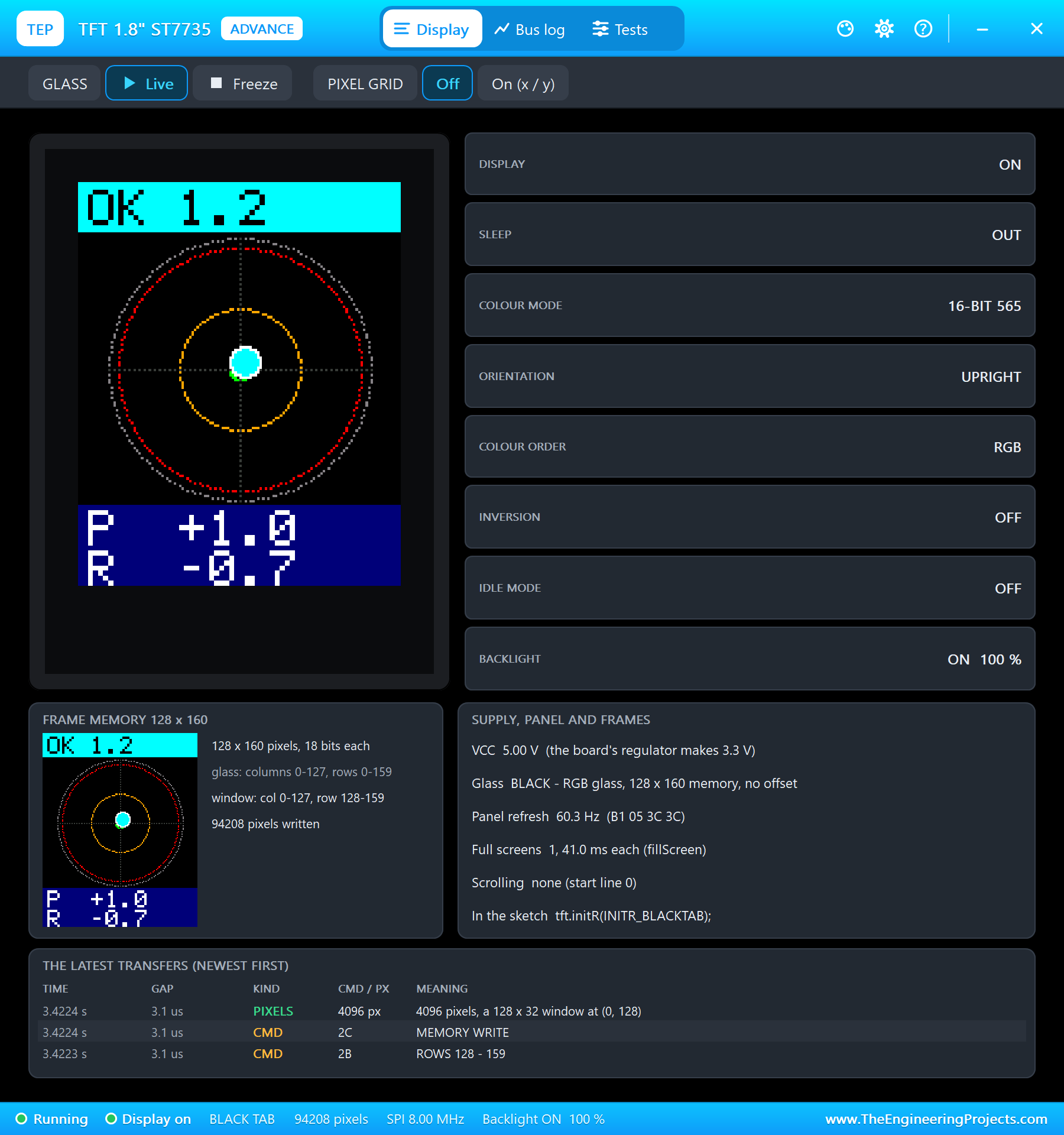
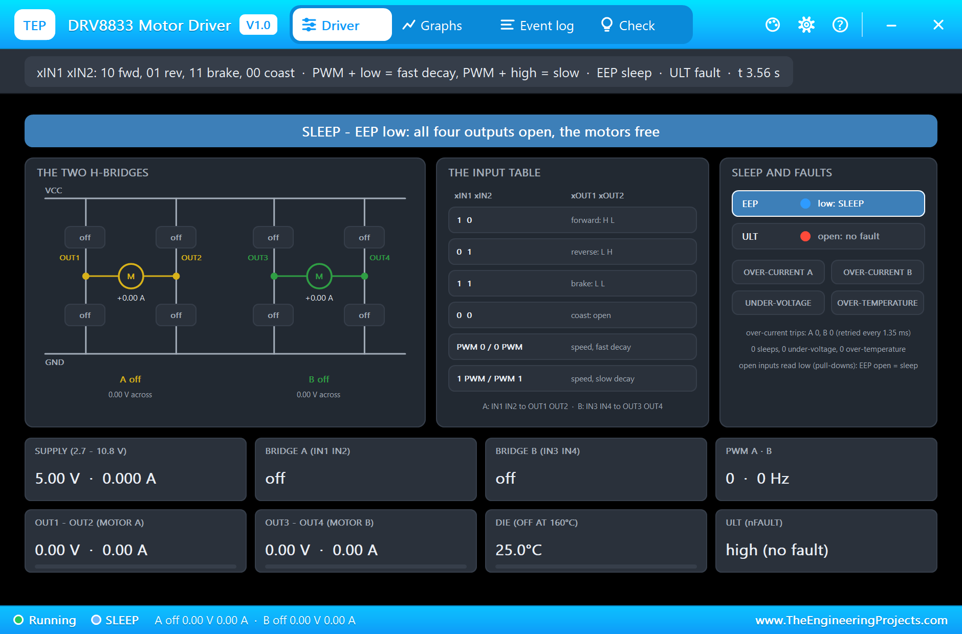
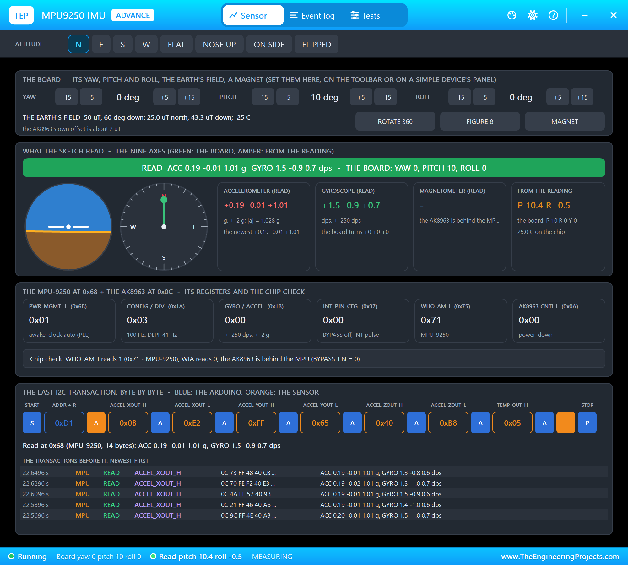
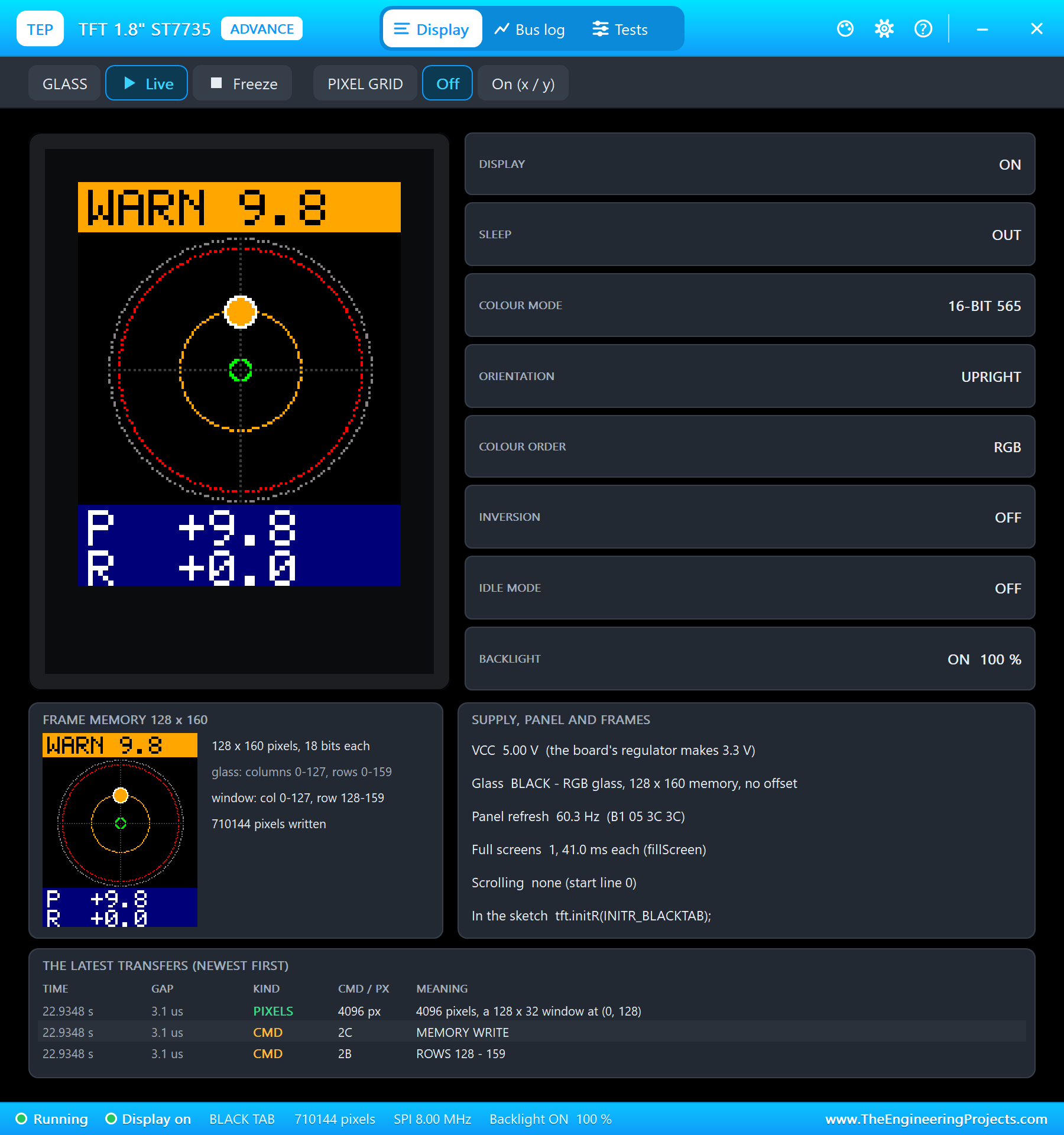
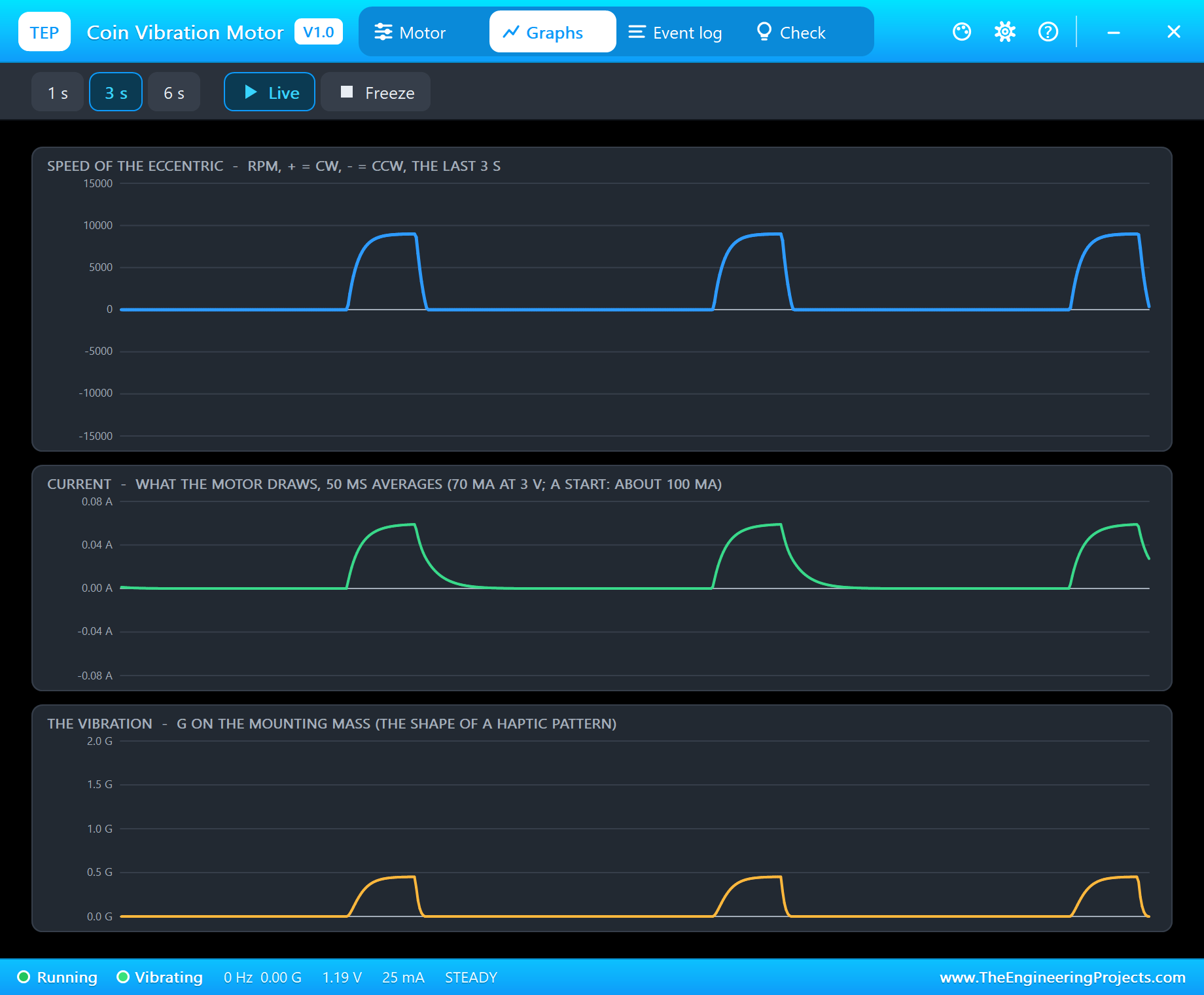
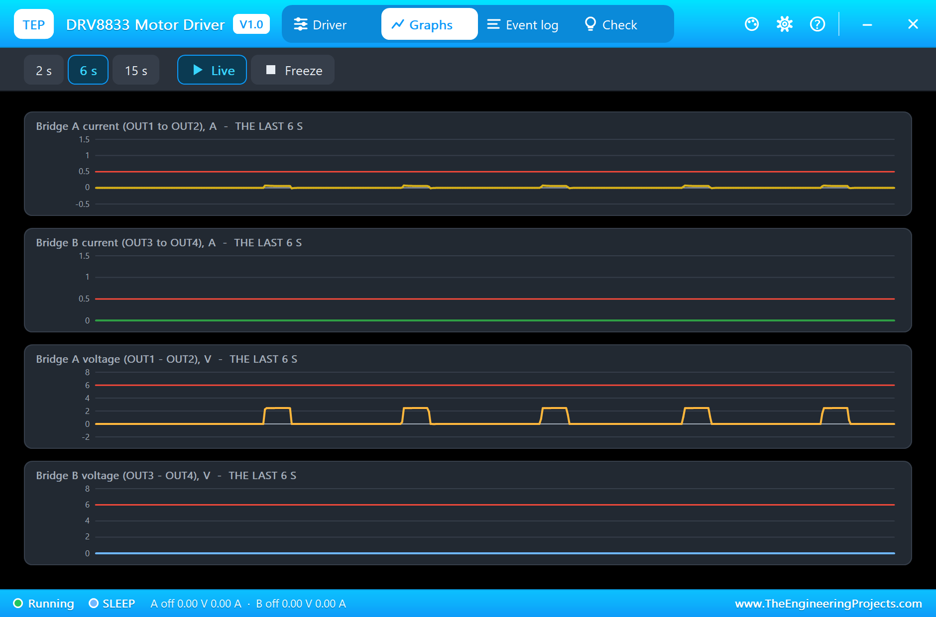
It is a great project for learning how an IMU measures tilt, why sensor fusion is needed, how to talk to an I2C sensor and an SPI display register by register from Python, and how to drive a small motor with PWM and a brake. In the simulation, the GY-9250's pop-up turns the board and shows what the program reads, the TFT's pop-up shows a big copy of the glass, the DRV8833's pop-up shows its bridges, and the coin motor's pop-up shows its speed and its vibration in G.
Components Used in the Proteus Simulation
All the parts come from our Proteus libraries, each with its own tutorial. The project zip at the end includes every LIB and DLL file and the TEPPi Python runtime.
| Part | Proteus device | Library post | Connection |
|---|---|---|---|
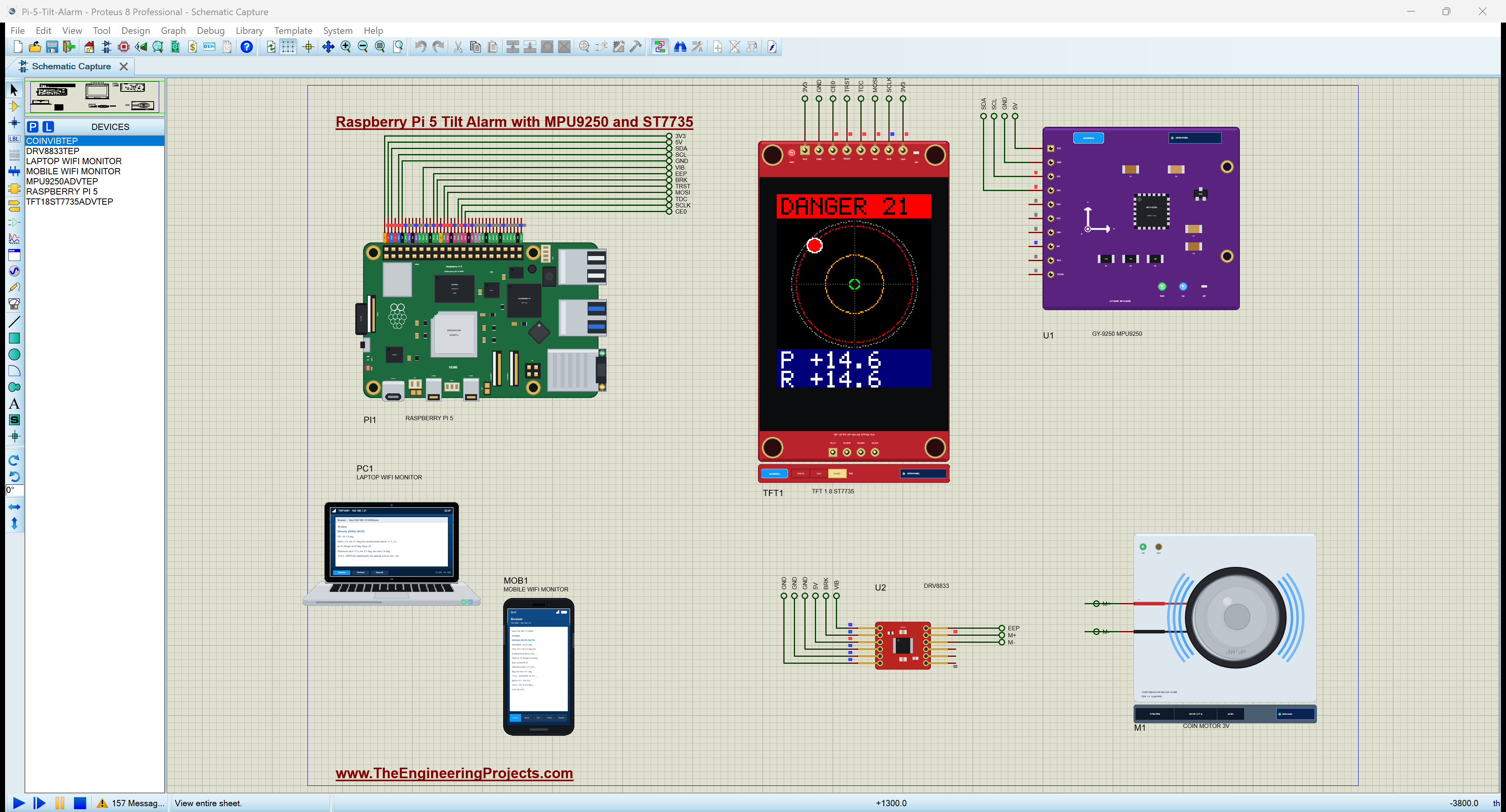
| Raspberry Pi 5 | RASPBERRY PI 5 | Raspberry Pi 5 Library for Proteus | PI1, Ethernet 192.168.1.51 |
| GY-9250 (MPU-9250) | MPU9250ADVTEP | MPU9250 Library for Proteus | U1, I2C1 at 0x68 |
| TFT 1.8" ST7735 128 x 160 | TFT18ST7735ADVTEP | TFT ST7735 Library for Proteus | TFT1, SPI0 |
| DRV8833 motor driver | DRV8833TEP | DRV8833 Motor Driver Library for Proteus | U2, IN1 GPIO18, IN2 GPIO23, EEP GPIO22 |
| Coin vibration motor 3 V | COINVIBTEP | Coin Vibration Motor Library for Proteus | M1, on bridge A |
| Laptop WiFi Monitor | LAPTOP WIFI MONITOR | Laptop WiFi Monitor | PC1 |
| Mobile WiFi Monitor | MOBILE WIFI MONITOR | Mobile WiFi Monitor | MOB1 |
The parts are compact on purpose: one sensor module, one small display, one tiny driver and a 10 mm motor, all powered from the Raspberry Pi's own 3.3 V and 5 V pins. The coin motor is the kind that buzzes in phones and fitness bands, so the alarm can be felt in the hand of whoever holds the controller, even in a noisy cab.
Proteus Simulation of the Tilt Alarm: the Circuit
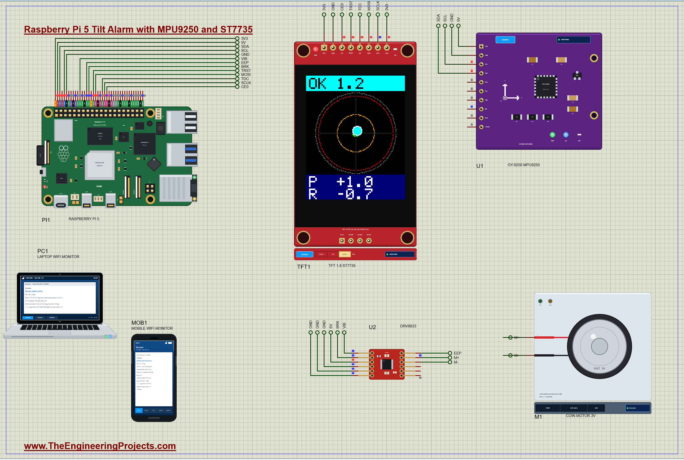
| Part | Pins | Raspberry Pi 5 |
|---|---|---|
| U1 GY-9250 | VCC / GND / SDA / SCL | 5 V (pin 2) / GND / GPIO2 (pin 3) / GPIO3 (pin 5); AD0 open = 0x68 |
| TFT1 ST7735 | VCC, LED / GND | 3.3 V (pin 1) / GND |
| TFT1 ST7735 | CS / RESET / A0 | CE0 GPIO8 (pin 24) / GPIO24 (pin 18) / GPIO25 (pin 22) |
| TFT1 ST7735 | SDA / SCK | MOSI GPIO10 (pin 19) / SCLK GPIO11 (pin 23) |
| U2 DRV8833 | IN1 / IN2 / EEP | GPIO18 (pin 12, PWM) / GPIO23 (pin 16) / GPIO22 (pin 15) |
| U2 DRV8833 | VCC / GND / IN3, IN4 | 5 V / GND / GND (bridge B unused) |
| U2 DRV8833 | OUT1 / OUT2 | the coin motor's + / - |
The GY-9250 takes 5 V on VCC because it has its own 3.3 V regulator for the chip, and its I2C pull-ups go to that 3.3 V, so the Pi's pins never see 5 V. The ST7735's pins on this board are labelled the Arduino way: SDA is really the SPI data input (MOSI) and A0 is the data / command line, often called DC. The DRV8833 runs from the 5 V pin: the motor is rated for 3 V, so the program never gives it more than 60 % of 5 V on average, which is the job of PWM.
How the Tilt Alarm Works
An Accelerometer Finds Gravity
An accelerometer at rest measures one thing: the push of whatever holds it up against gravity, 1 g pointing straight up. Flat on a table, the whole 1 g falls on the Z axis; tilt the board and part of it moves onto X or Y. The MPU-9250 here uses X forward, Y to the left and Z up, so the nose rising puts gravity onto X, and the right side going down puts it onto Y. The pitch is the angle of the X axis above the horizon, atan2(ax, sqrt(ay² + az²)), and the roll is the angle about X, atan2(ay, az). With the +-2 g range one g is 16,384 counts, so the readings are fine down to a hundredth of a degree.
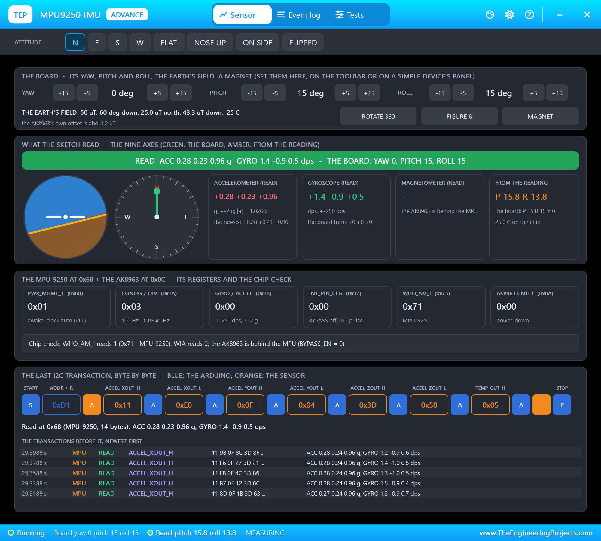
Worked example from the run: in DANGER the pop-up shows the program reading 0.28, 0.23 and 0.96 g. The pitch is atan2(0.28, sqrt(0.23² + 0.96²)) = atan2(0.28, 0.987) = 15.8 degrees and the roll atan2(0.23, 0.96) = 13.5 degrees; the pop-up, with all the digits, gives 15.8 and 13.8. The board was turned 15 and 15 degrees: the difference is the chip's own small offset, which ZERO removes.
Why the Gyroscope Is Needed
The accelerometer has two weaknesses. It cannot tell gravity from any other acceleration, so a machine that brakes, a crane that swings or an engine that vibrates all look like tilt; and its readings are noisy. The gyroscope has the opposite character: it measures how fast the board turns, in degrees a second, smoothly and immune to acceleration, but it never knows the angle itself, only the change, and its small bias adds up. In this run the gyro read 1.39 degrees a second while standing still; integrated without correction, that would drift by 83 degrees in a minute. The program measures the bias in its first second and subtracts it, but a little always remains.
The Complementary Filter
The complementary filter takes the best of both. Every reading, the new angle is the old angle plus the gyro's turn since the last reading, mixed with a small share of the accelerometer's angle: angle = a x (angle + rate x dt) + (1 - a) x accelerometer. With a time constant of 1 s, a = 1 / (1 + dt) = 0.98 at 50 readings a second, so the gyro carries 98 % and the accelerometer 2 %. A quick move is followed at once by the gyro; a wobble or a jolt from the accelerometer only moves the result 2 % at a time; and over a few seconds the accelerometer slowly pulls the angle back to the truth, so the gyro's drift never builds up. One lesson from building this project: the filter must use the real time between readings, not the planned 20 ms. An early version assumed 20 ms while the display updates stretched some loops, so it under-counted every turn and the angle crept to its value over two seconds.
Pitch and Roll Make the Tilt
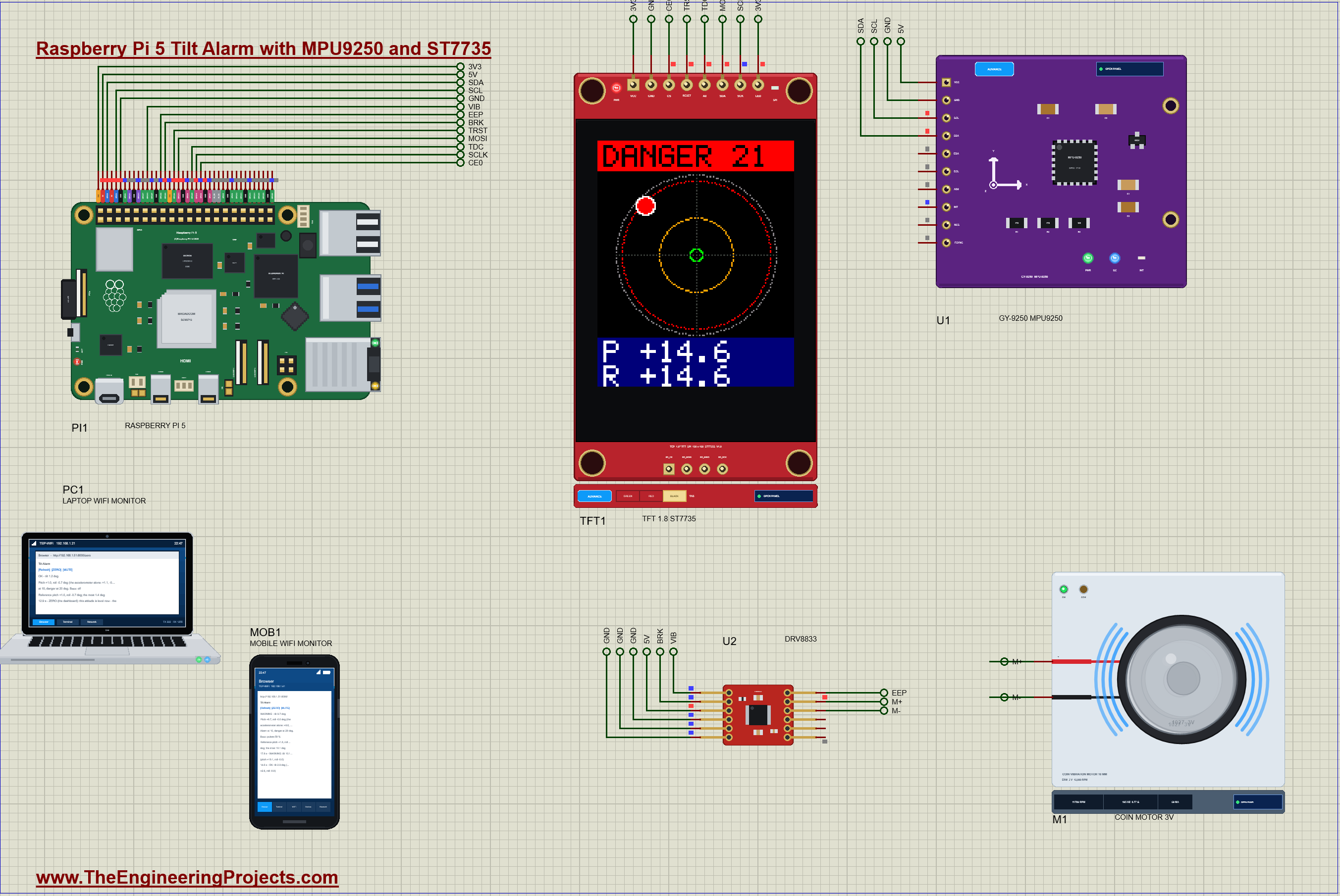
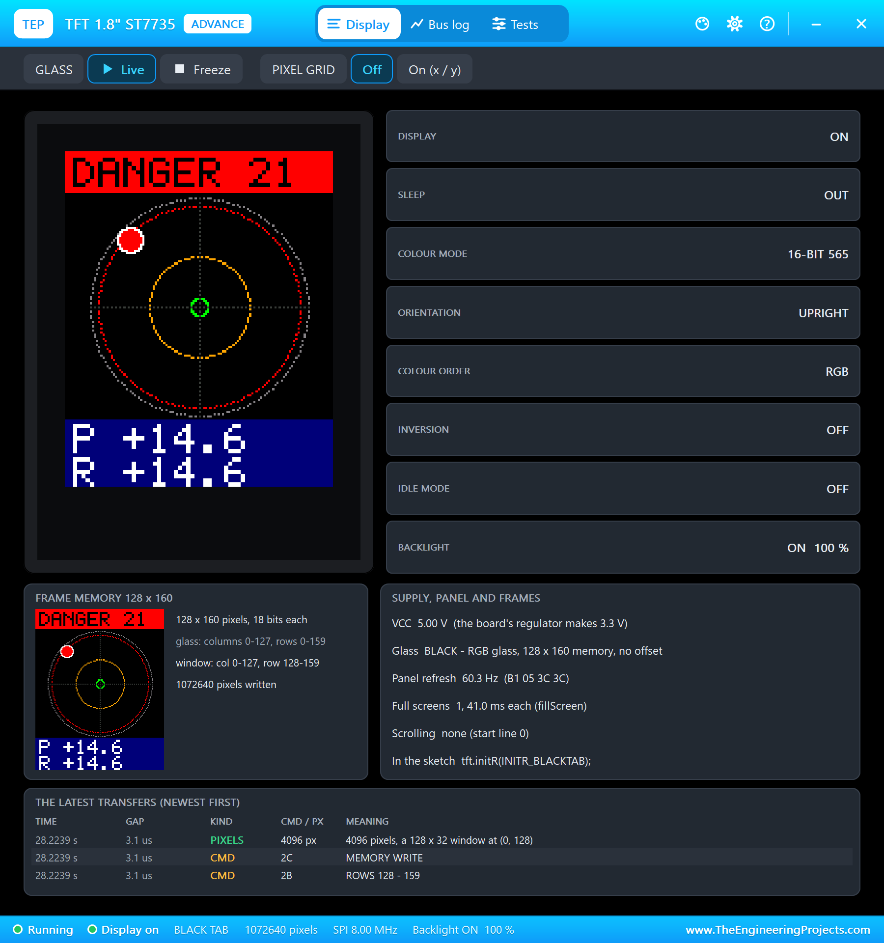
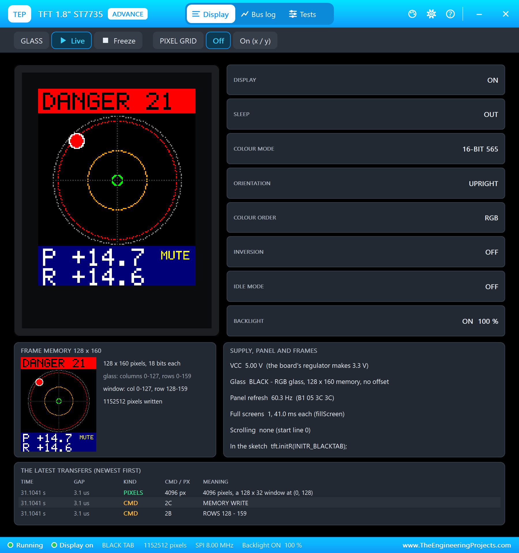
The alarm cares about one number: how far the board leans from the vertical in any direction, the angle between its Z axis and straight up. It is not the pitch plus the roll, and not the larger of the two: the Z axis is tipped by both, and cos(tilt) = cos(pitch) x cos(roll). Worked example from the run: at a pitch of 14.6 and a roll of 14.6 degrees, cos(tilt) = 0.9677 x 0.9677 = 0.9365, so the tilt is 20.5 degrees; the program, with more digits, says 20.6. Adding the angles would have said 29 degrees, and the larger one only 14.6: one would alarm far too early, the other far too late.
ZERO, Two Levels and Hysteresis
No sensor is mounted perfectly on a machine, and no chip is perfect either: flat on the table, this one reads a pitch of +1.0 and a roll of -0.7 degrees. ZERO stores the present angles as the reference and subtracts them from then on, so the machine's own level becomes zero. The alarm has two levels: WARNING from 10 degrees, a short buzz every second that says "careful", and DANGER from 20 degrees, a steady buzz that says "stop". Each level is left only 1 degree inside its threshold, under 9 and under 19 degrees: without that hysteresis, a machine standing at exactly 10 degrees would switch the alarm on and off with every bit of noise. MUTE silences the buzz while the alarm stays on the screen and the dashboard, and the mute ends by itself when the tilt is back under the warning level, so the next danger is never silent.
Driving the ST7735 over SPI
The ST7735S controller listens on a 4-wire SPI bus: CS low selects it, each byte goes out on the data line with the clock, and the A0 line says whether the byte is a command (low) or its data (high). After a reset the chip needs SLPOUT and then at least 120 ms before it takes more commands, then the colour mode (16 bits a pixel, RGB565), the orientation (MADCTL, which also depends on the colour of the glass's tab: this one is a black tab) and DISPON. A picture is sent as a window: the column range, the row range, then RAMWR and the pixels, two bytes each. The bubble window is 128 x 108 pixels, 27,648 bytes, about 28 ms at 8 MHz, so the program redraws it only when the bubble has moved 0.3 degree, at most five times a second, and redraws the text only when it changes.
A Bull's-Eye Level
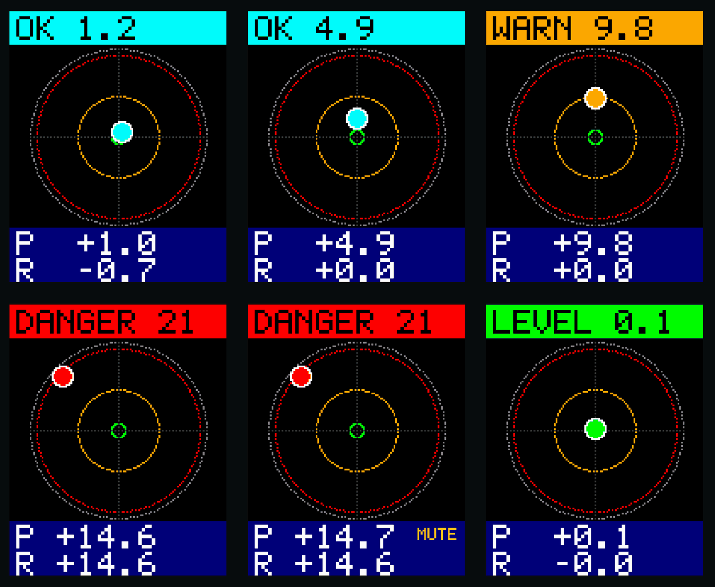
The screen copies a real circular spirit level, where the bubble floats to the high side: nose up sends it up, the right side down sends it to the left. Each degree moves it 2.4 pixels, so the green ring is 1 degree, the orange ring 10 and the red ring 20, and the bubble takes the colour of the state. Above it the state and the tilt, below it the pitch and the roll, so the TFT alone is a complete digital level.
Haptic Alarm: PWM and a Brake
The coin motor is an ERM, an eccentric rotating mass: a small off-centre weight spins inside the can at about 12,000 RPM on 3 V and shakes whatever the motor is glued to. The DRV8833 drives it from bridge A: IN1 gets a 1 kHz PWM and IN2 stays low, so in the off time of each period the bridge opens and the motor coasts. The duty cycle sets the average voltage: 50 % of 5 V is 2.5 V for the warning pulses, 60 % is 3.0 V for the steady danger buzz. To stop crisply, the program brakes: both inputs high switch on both low-side transistors and short the motor, which stops it in about 30 ms instead of letting it spin down. Then both inputs go low and EEP, the chip's sleep pin, goes low too, so the driver draws only microamps between alarms.
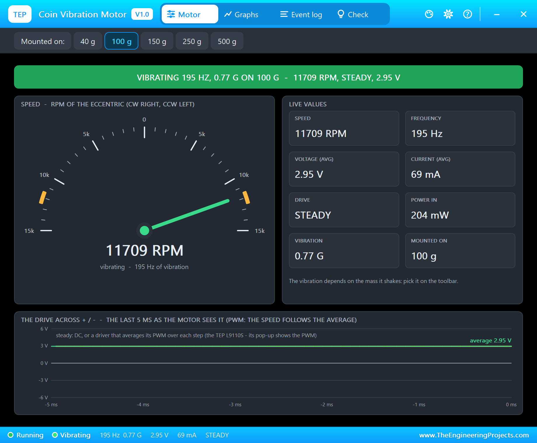
Worked example: the vibration force of an ERM grows with the square of its speed. In the run the danger buzz spins the motor at 11,709 RPM and gives 0.77 G on a 100 g mass; the warning pulses reach about 9,000 RPM, so they shake with roughly (9,000 / 11,709)² x 0.77 = 0.45 G, a gentler buzz, which is exactly what the pop-up's graph shows.
The Python Code Explained
The whole program is included in the download. It needs no extra library: lgpio for the GPIO, the I2C bus and the PWM, spidev for the SPI bus, threading and http.server for the dashboard. At the top are the numbers that decide the behaviour:
LEVEL, WARN, DANGER, HYST = 1.0, 10.0, 20.0, 1.0         # degrees of tilt
PWM_HZ, WARN_DUTY, DANGER_DUTY = 1000, 50, 60            # % of 5 V: 2.5 V and 3.0 V average for the 3 V motor
Talking to the MPU-9250
The program first reads WHO_AM_I (0x71 for an MPU-9250), resets the chip and sets it up register by register:
        lgpio.i2c_write_byte_data(self.h, 0x6B, 0x01)            # awake, the gyro's PLL as the clock
        lgpio.i2c_write_byte_data(self.h, 0x1A, 0x03)            # CONFIG: the gyro's low-pass filter at 41 Hz
        lgpio.i2c_write_byte_data(self.h, 0x19, 0x09)            # SMPLRT_DIV: 1 kHz / (1 + 9) = 100 samples a second
One burst of 14 bytes from ACCEL_XOUT_H brings the three accelerations, the temperature and the three rotations, each a signed 16-bit value with the high byte first:
n, b = lgpio.i2c_read_i2c_block_data(self.h, 0x3B, 14) acc = [c / 16384.0 for c in v[0:3]] # g
gyro = [c / 131.0 for c in v[4:7]] # deg/sFrom the Readings to the Tilt
The accelerometer's angles, then the gyro's rates with their bias taken away (a nose-up turn is a negative turn about the Y axis, which points left), then the filter with the real time since the last reading:
return math.degrees(math.atan2(ax, math.sqrt(ay * ay + az * az))), math.degrees(math.atan2(ay, az)) rate_roll, rate_pitch = gyro[0] - bias[0], -(gyro[1] - bias[1]) # (X forward, Y left, Z up: a nose-up turn is -Y) a = TAU / (TAU + dt) # 0.98 at 50 readings a second
pitch = a * (pitch + rate_pitch * dt) + (1 - a) * ap
roll = a * (roll + rate_roll * dt) + (1 - a) * ar tilt = math.degrees(math.acos(math.cos(math.radians(p)) * math.cos(math.radians(r)))) # Z axis against the verticalThe state keeps its level until the tilt is a degree inside the threshold:
    if tilt >= DANGER or (old == 'DANGER' and tilt > DANGER - HYST):
        return 'DANGER'
The TFT
The ST7735's setup after its reset, and the three commands that send any rectangle of pixels:
        self.cmd(0x11); time.sleep(0.26)                  # SLPOUT, then the 120 ms the datasheet asks for (and more)
        self.cmd(0x3A, [0x05])                            # COLMOD: 16 bits a pixel
        self.cmd(0x36, [0xC0])                            # MADCTL: rotation 0 on a black-tab glass (MY + MX, RGB order)
self.cmd(0x2A, [0, x, 0, x + w - 1])
self.cmd(0x2B, [0, y, 0, y + h - 1])
self.cmd(0x2C, pixels)The bubble is drawn into a frame buffer first; its place is the tilt turned the other way, because the bubble floats to the high side:
bx, by = -roll * K, -pitch * KThe Motor, ZERO and MUTE
A buzz is a PWM on IN1; a stop is a brake, both inputs high, before the driver sleeps:
lgpio.tx_pwm(chip, IN1, PWM_HZ, duty) lgpio.tx_pwm(chip, IN1, 0, 0)
lgpio.gpio_write(chip, IN1, 1); lgpio.gpio_write(chip, IN2, 1)ZERO adds the present angles to the reference, and a mute ends by itself when the alarm clears:
s['zero_pitch'] += s['pitch']; s['zero_roll'] += s['roll'] if state in ('LEVEL', 'OK') and s['muted']:The pages are / (the dashboard), /zero, /mute and /data (everything as JSON). The dashboard puts its three links first and stays short, because the WiFi Monitors show one screen of a page. The terminal prints a line a second: the angles, the tilt, the state, the largest gyro rate of that second, how many readings the loop made and the buzz.
How to Run the Proteus Simulation
- Download the project zip below and install the library files and the TEPPi folder (the steps are under the download button).
- Open Pi-5-Tilt-Alarm.pdsprj from the Proteus Simulation folder. Keep tilt_alarm.py and the DLL files next to it.
- Press Play. The TFT shows the bubble and the Pi's terminal prints the angles every second.
- Open the Laptop WiFi Monitor (PC1) or the Mobile WiFi Monitor (MOB1), press Go and then ZERO.
- Click the GY-9250 for its pop-up and turn the board with PITCH and ROLL +5 or +15: WARNING at 10 degrees, DANGER at 20, the coin motor buzzing; MUTE silences it, FLAT clears it.
Simulation Results: the Tilt Alarm in Proteus
Here is the run that made the screenshots of this tutorial, 36.6 seconds of simulation. The times below are the program's own, as it printed them on the Pi's terminal; the parts' numbers come from their pop-ups.
Power-Up: a Degree Off on a Flat Table
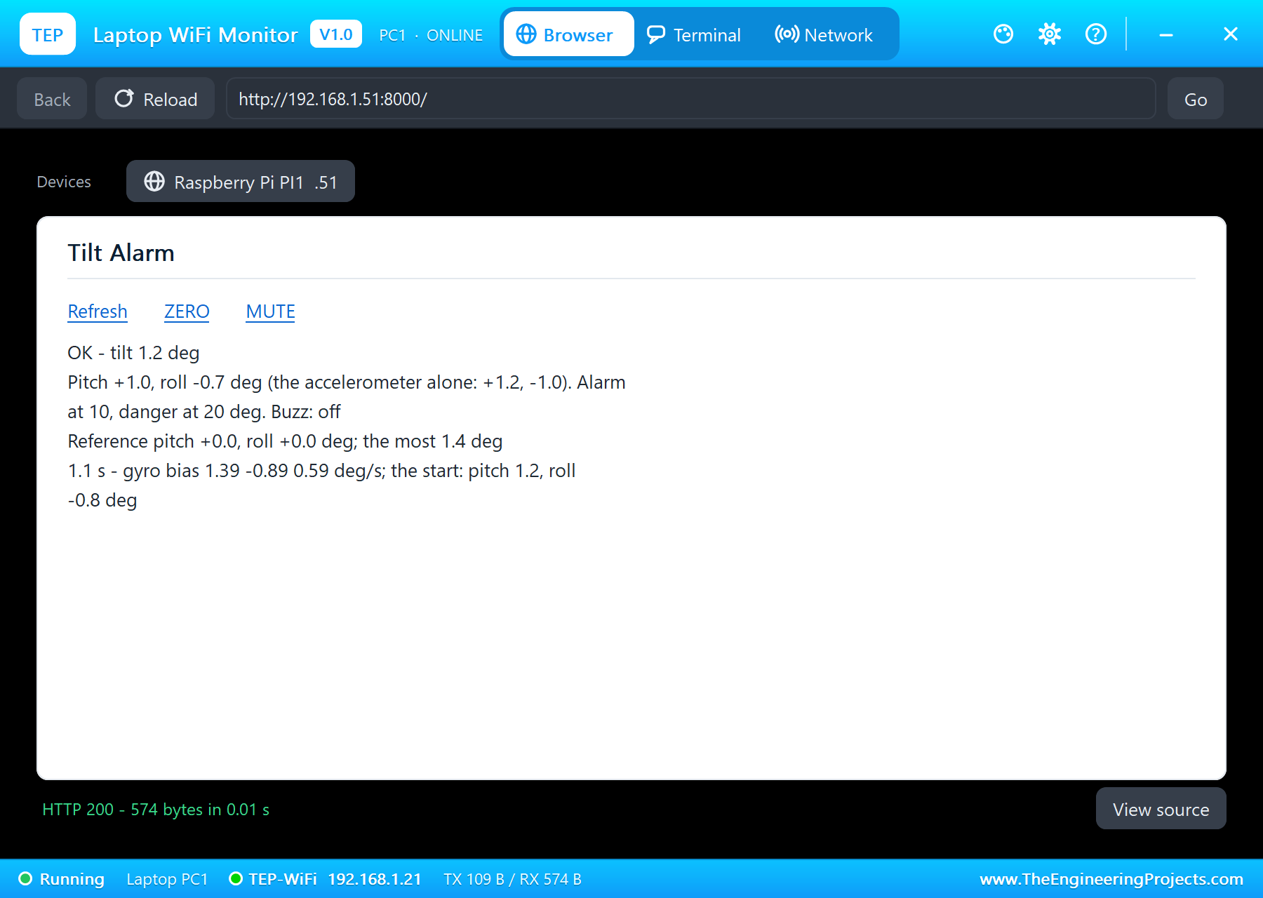
The program finds the MPU-9250 (WHO_AM_I 0x71), measures the gyro's bias, 1.39, -0.89 and 0.59 degrees a second, and starts reading 50 times a second. The board lies flat, the pop-up says yaw, pitch and roll 0, yet the chip reads a pitch of +1.0 and a roll of -0.7 degrees: its own small offsets. So the TFT says OK 1.2, not LEVEL, with the bubble just off the centre. The DRV8833 sleeps, all four outputs open, with no fault.
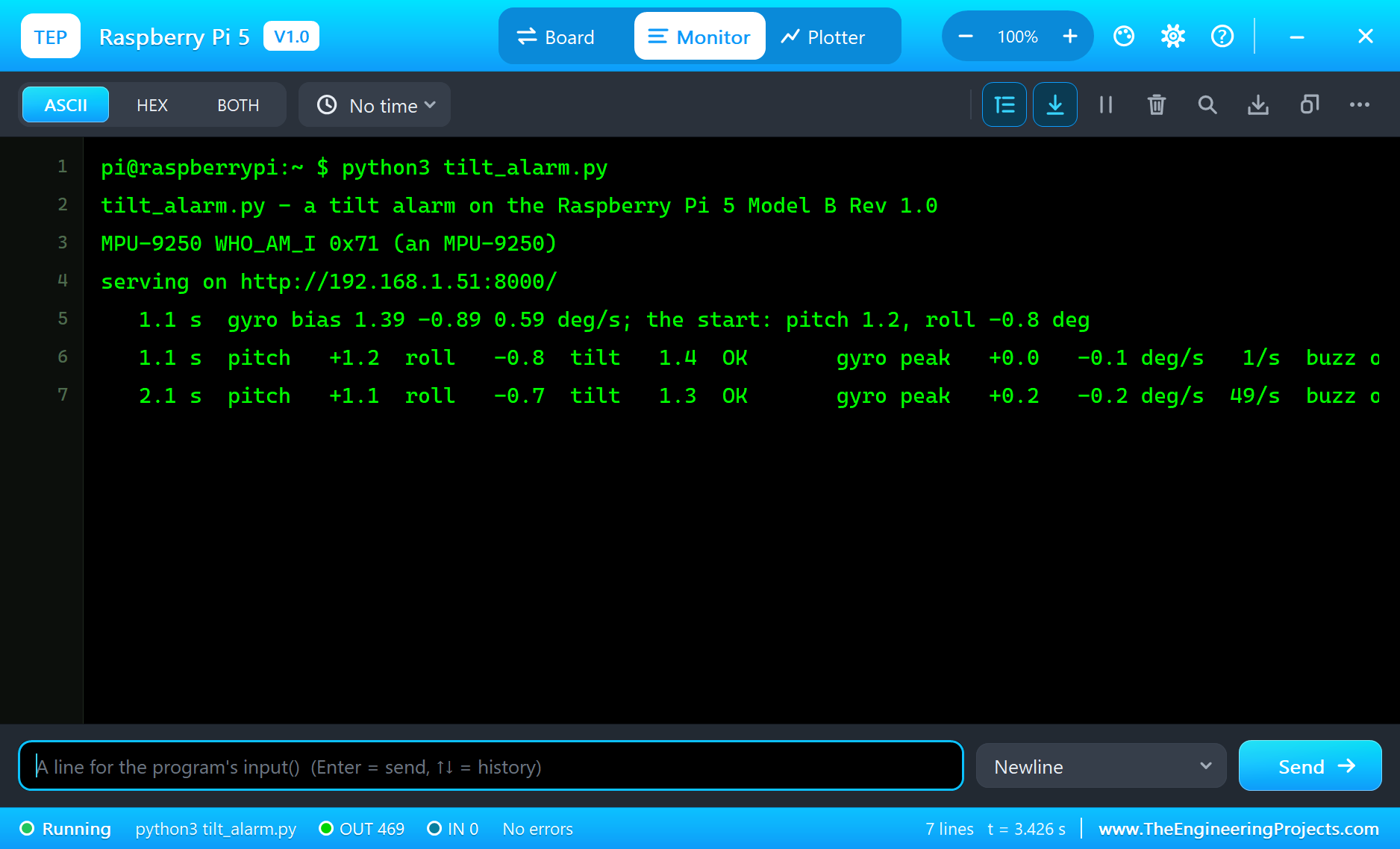
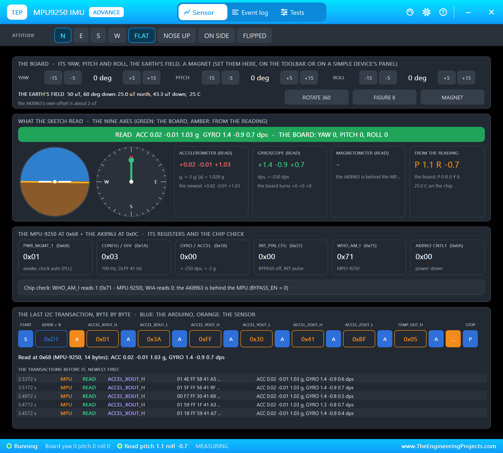
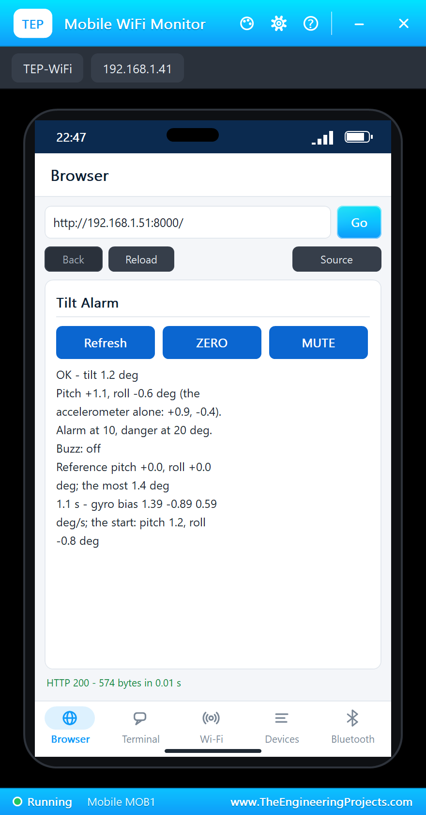
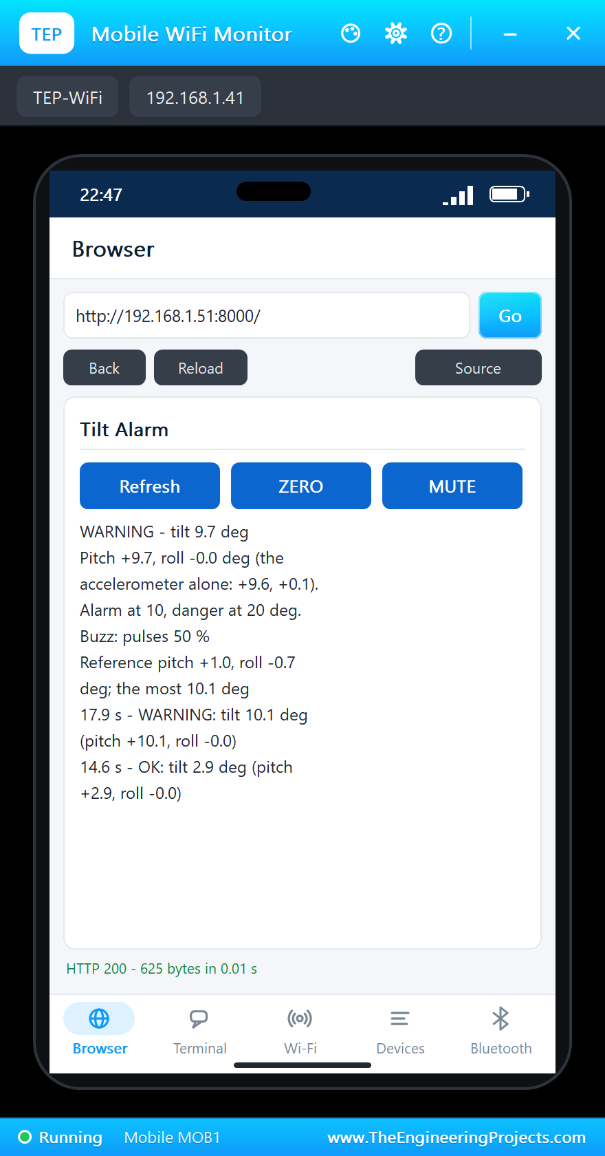
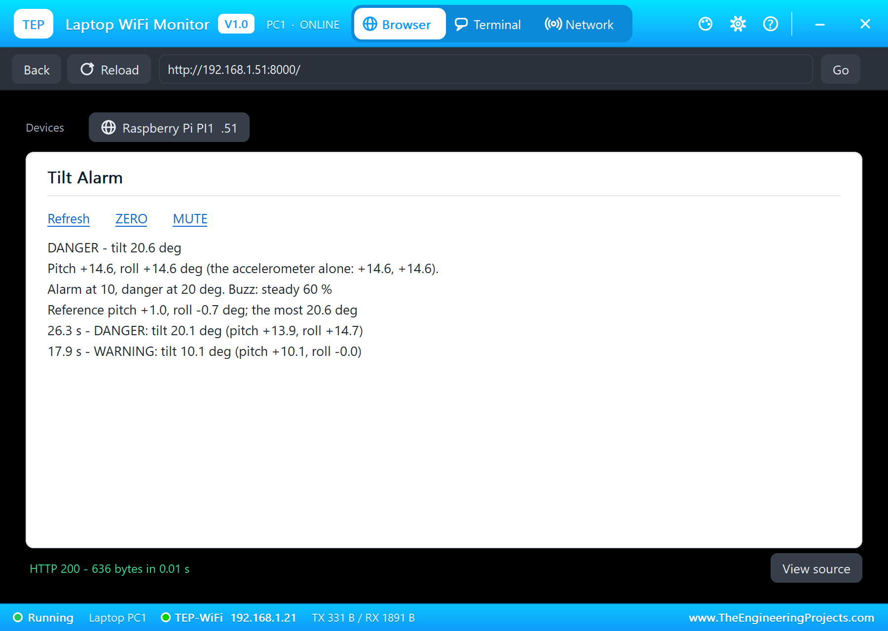
Both dashboards show the same: OK, tilt 1.2 degrees, the angles from the filter and from the accelerometer alone, the levels and the buzz off.
ZERO: Level
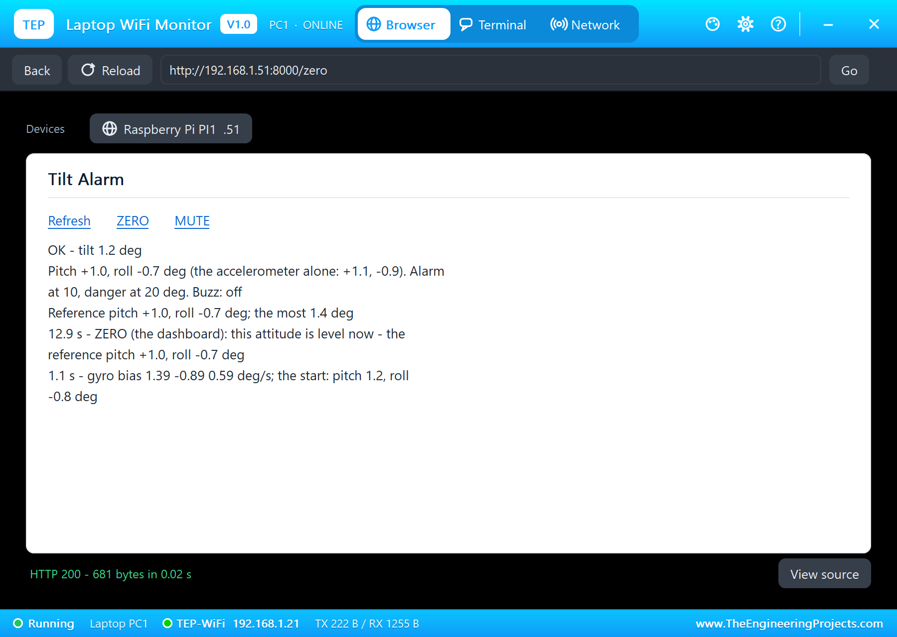
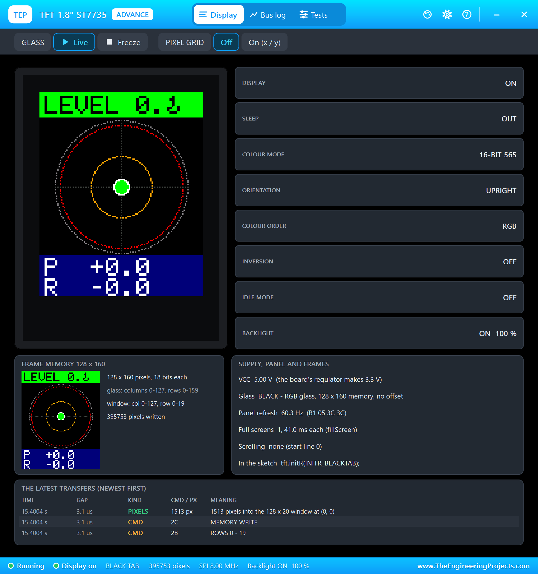
At 12.9 s ZERO on the laptop: "ZERO (the dashboard): this attitude is level now - the reference pitch +1.0, roll -0.7 deg", and in the same moment "LEVEL: tilt 0.0 deg". The page the laptop got back still shows OK 1.2 in its first line, because the program built it in the instant before its next reading, 20 ms later; the reference line and the event below already show the change, and the TFT says LEVEL with a green bubble in the middle.
Five Degrees, Then Ten: WARNING
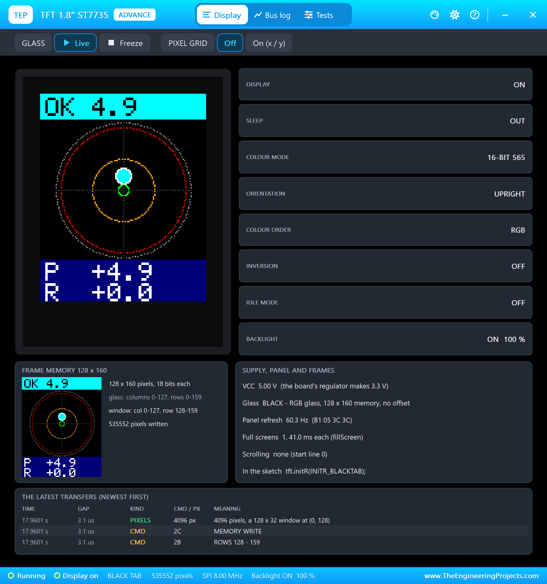
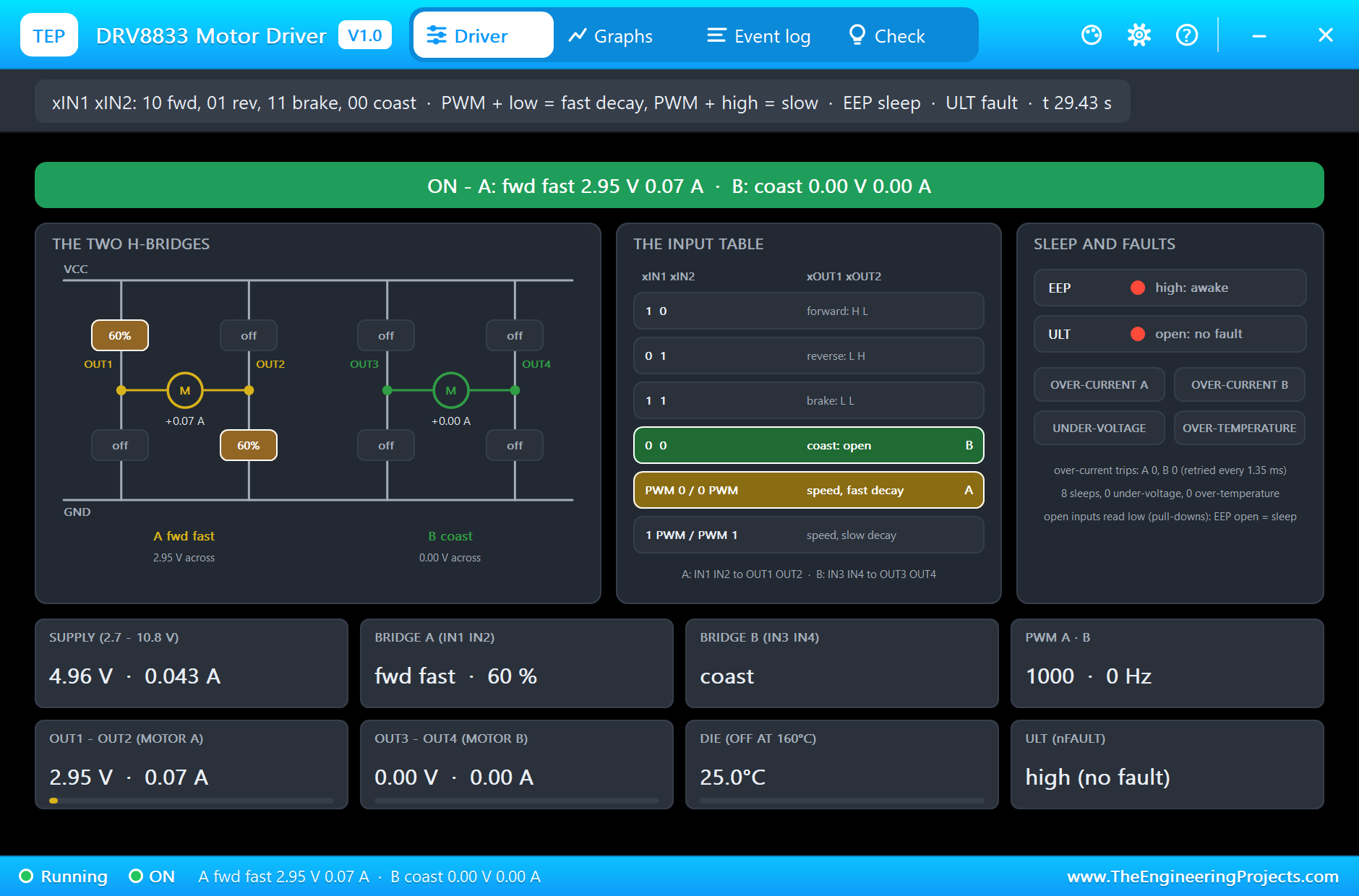
At 14.6 s PITCH +5 on the GY-9250's pop-up: the gyro sees the turn at up to 49.6 degrees a second and the state becomes OK, settling at 4.9 degrees with the bubble pushed up. At 17.9 s PITCH +5 again: "WARNING: tilt 10.1 deg". The gyro carried the angle a little past 10, and the accelerometer then pulled it back to 9.8 over the next seconds: its small offsets do not subtract exactly at every angle. The state stays WARNING, because it is left only under 9 degrees. The motor now gives a 0.2 s buzz every second at 50 %: the coin motor's graph shows each pulse climbing to about 9,000 RPM and its vibration to about 0.45 G, and the DRV8833's graph shows the pulses of voltage on bridge A.
A Second Axis: DANGER
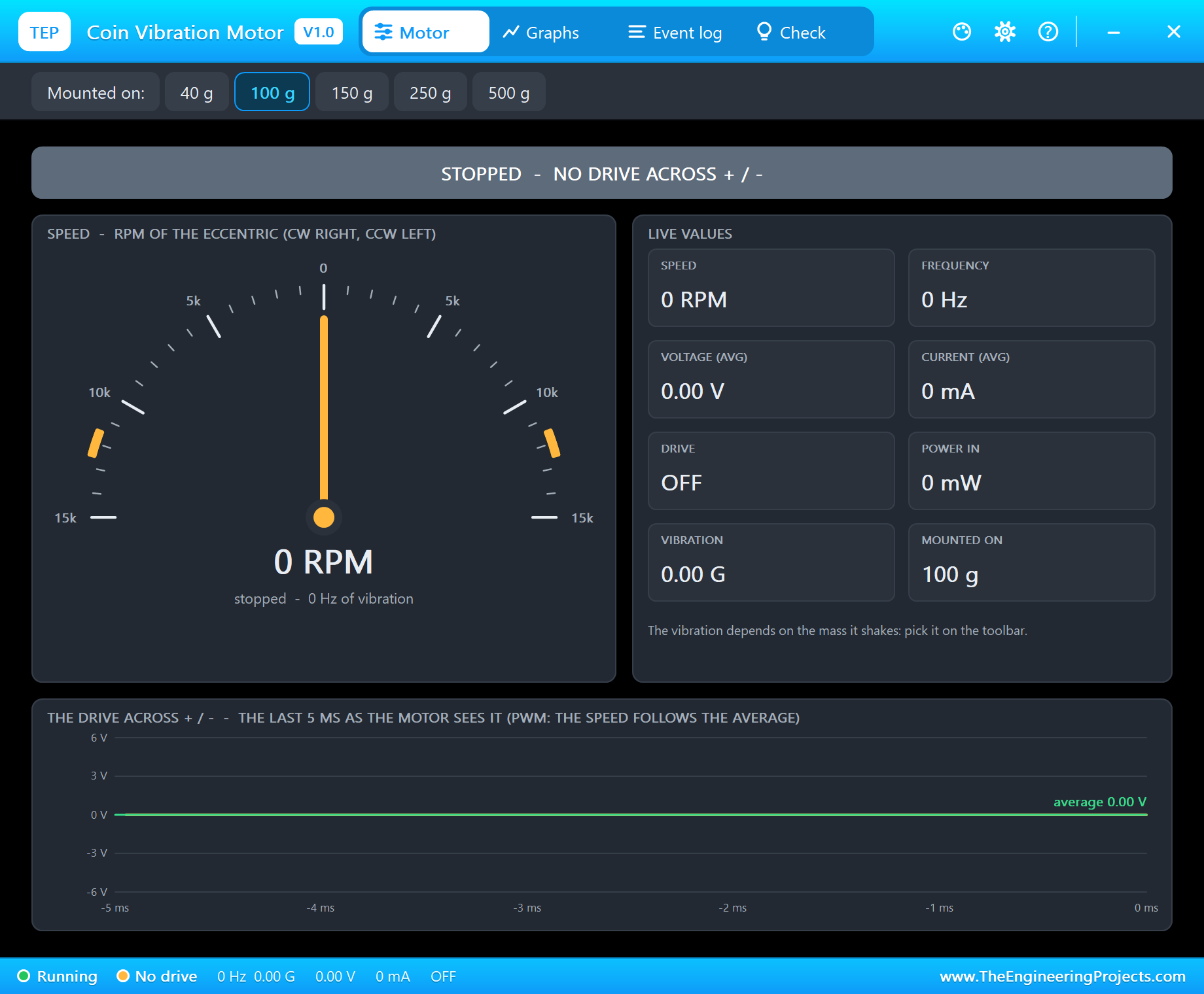
At 24.2 s ROLL +15 (the gyro saw 90 degrees a second): the pitch stays 9.8 and the roll goes to 14.9, a tilt of 17.8 degrees, still WARNING. At 26.3 s PITCH +5 once more: "DANGER: tilt 20.1 deg", settling at 20.6 with a pitch and a roll of 14.6 each. The buzz turns steady at 60 %: the coin motor sees 2.95 V on average and spins at 11,709 RPM, 195 Hz of vibration, 0.77 G on its 100 g mass, taking 69 mA; the DRV8833 shows bridge A forward with a fast-decay PWM at 60 %. On the sheet the motor is drawn shaking and the TFT is red.
MUTE, Then Back to Level
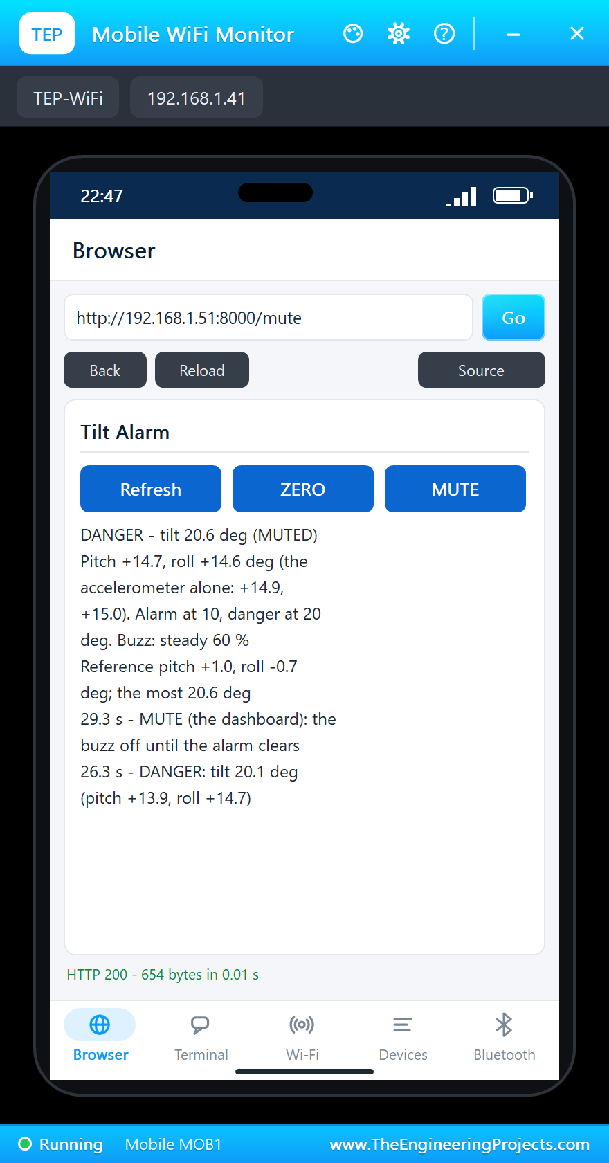
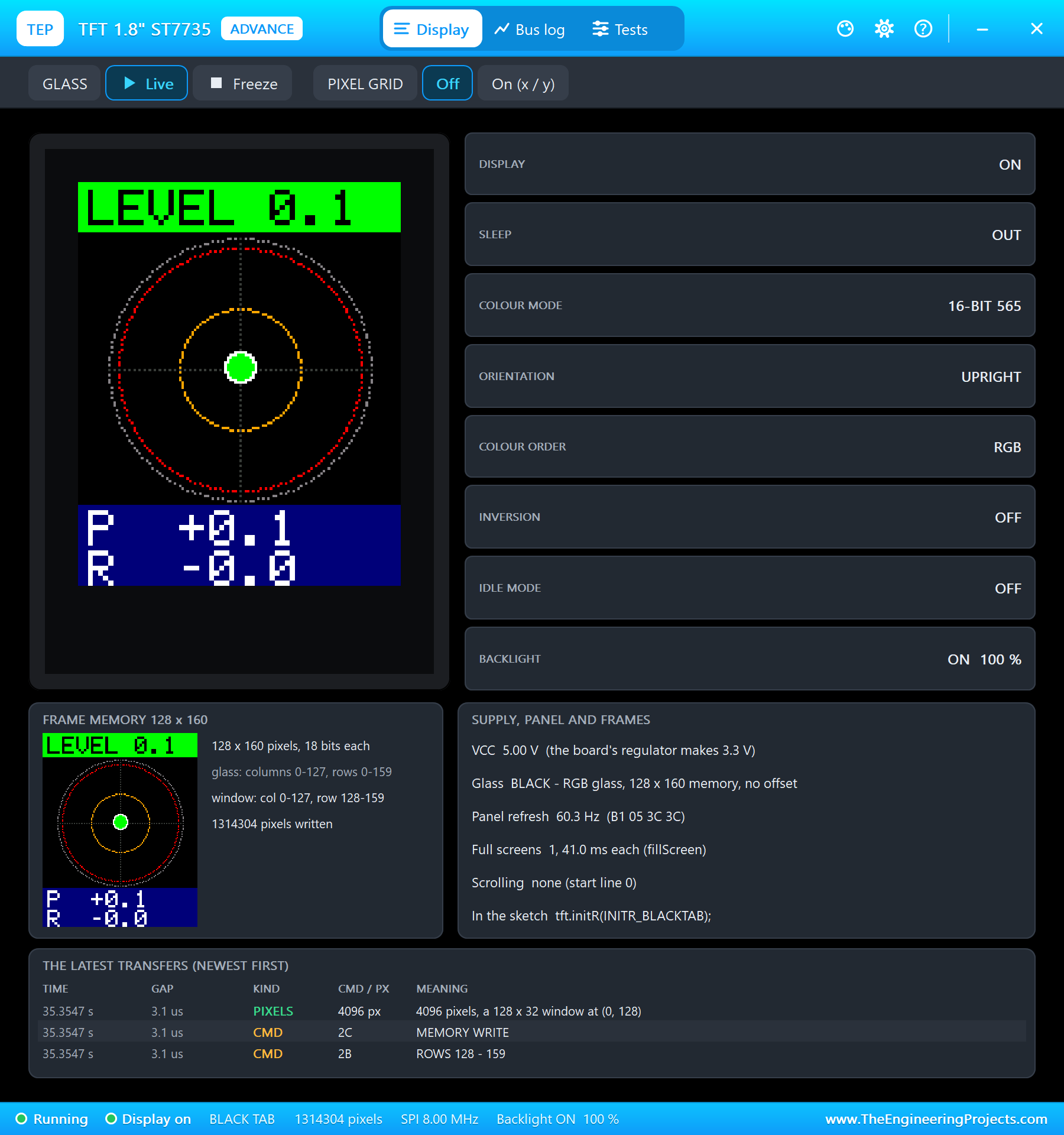
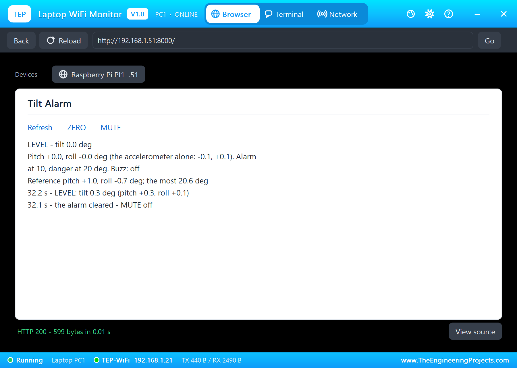
At 29.3 s MUTE on the phone: "MUTE (the dashboard): the buzz off until the alarm clears". The motor brakes and stops, the TFT stays red with MUTE in its corner and the dashboard says DANGER (MUTED). At 32.0 s FLAT on the pop-up turns the board back in one quick move, the gyro reading -89 degrees a second on both axes: WARNING, then at 32.1 s OK and "the alarm cleared - MUTE off", and at 32.2 s LEVEL at 0.3 degrees, settling at 0.1 a second later.
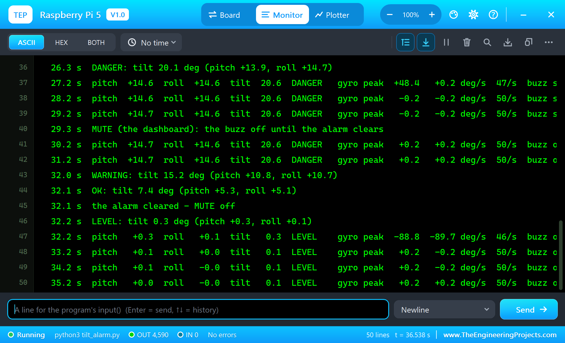
The Numbers of the Run
| What | Result |
|---|---|
| The chip's offset | pitch +1.0, roll -0.7 degrees flat; removed by ZERO |
| The gyro | a bias of 1.39 / -0.89 / 0.59 deg/s; turns seen at up to 90 deg/s |
| WARNING | from 10.1 degrees; held at 9.8 by the hysteresis; 0.2 s pulses at 50 % |
| DANGER | from 20.1 degrees; 20.6 at 14.6 / 14.6; a steady buzz at 60 % |
| The coin motor | 11,709 RPM, 195 Hz, 0.77 G on 100 g, 69 mA at 2.95 V |
| The loop | 50 readings a second; the bubble at most 5 frames a second |
| Simulation | 36.6 s of simulation |
Download the Project Files
Click the button below to download Raspberry-Pi-5-Tilt-Alarm-MPU9250-ST7735-Proteus-Simulation-v1.0.zip (about 14.0 MB, without the source code of the models):
Raspberry Pi 5 Tilt Alarm with MPU9250 and ST7735 in Proteus Simulation V1.0- Proteus Simulation: Pi-5-Tilt-Alarm.pdsprj, the program tilt_alarm.py and copies of the models.
- Python Code: tilt_alarm.py, the complete program.
- Proteus Library Files: the LIB files of the Raspberry Pi 5, the GY-9250, the ST7735 TFT, the DRV8833, the coin vibration motor and the two WiFi Monitors.
- Proteus Model Files: the DLL models and the TEPPi folder, the Python 3.11 and the runtime that the Pi board runs.
- README.txt: the installation steps, the properties, the test results and the links to every library post.
No Proteus yet? Read How to Download and Install Proteus 7 and 8. New to libraries? Follow How to Install a New Library in Proteus.
How to Install the Project Files
- Close Proteus and extract the whole zip file, for example to your Desktop.
- Copy the files from Proteus Library Files into the LIBRARY folder of Proteus.
- Copy everything in Proteus Model Files, the DLL files and the TEPPi folder, into the MODELS folder.
- Start Proteus and open the project from the Proteus Simulation folder.
Changing the Code
The program is plain Python 3: edit tilt_alarm.py beside the project and press Play again; the Pi board runs the new file. The thresholds, the hysteresis, the PWM and the filter's time constant are at the top. The same program runs on a real Raspberry Pi 5 with Raspberry Pi OS, lgpio and spidev. For our other Pi 5 project with an accelerometer, which listens for shaking instead of tilt, see the Raspberry Pi 5 Earthquake Detector.
Ideas to Extend the Project
- Read the AK8963 magnetometer too and add a compass heading to the screen.
- Log the largest tilt of each day with its time, and show it on the dashboard.
- Let the dashboard change the warning and danger levels and save them.
- Add a relay output that stops the machine's motion in DANGER, not only buzzes.
- Detect a fall or a hard knock from a sudden spike in the acceleration.
- Use the FIFO and the data-ready interrupt so no sample is ever missed.
From Simulation to Real Hardware
- Mount the sensor rigidly: a loose module rattles, and every rattle is acceleration that looks like tilt.
- Remember what the accelerometer cannot know: a vehicle that brakes, turns or climbs for a long time pushes the angle away; the gyro covers short events only. Real machine tilt systems combine more sensors.
- Check the chip: many boards sold as MPU-9250 carry an MPU-6500 without the magnetometer; WHO_AM_I tells 0x71 from 0x70.
- Check the TFT's tab: black, green and red tab ST7735 glasses need different offsets and colour orders.
- Keep the motor off the logic supply's noise: a coin motor takes about 100 mA to start; a small capacitor across it and a separate 5 V feed help.
- Treat it as a helper: tilt alarms on cranes and work platforms are certified safety devices; this project is for learning.
Troubleshooting
- The TFT stays white: check A0 (GPIO25), RESET (GPIO24) and CS (CE0); its pop-up says what the controller is waiting for.
- The bubble moves the wrong way: it floats to the high side, as in a real level: nose up moves it up.
- The angles creep after a move: the filter must use the real time between readings, or the gyro's share comes out too small.
- The motor never buzzes: EEP (GPIO22) must be high, the DRV8833 needs 5 V on VCC, or MUTE is on.
- The terminal cannot start Python: the TEPPi folder is not in the MODELS folder.
Limitations of the Simulation
- The board is turned from the GY-9250 pop-up in steps; a real machine moves smoothly, vibrates and accelerates, which this run does not include.
- The coin motor's vibration is shown on its pop-up; nothing on the sheet shakes the sensor.
- The network is simulated: the dashboard travels between the Pi and the two monitors inside Proteus; the times in this tutorial are simulation time.
- Raspberry Pi is a trademark of Raspberry Pi Ltd. This project is not made or endorsed by them, by Labcenter or by the makers of the MPU-9250, the ST7735 and the DRV8833.
So, that was all about the Raspberry Pi 5 Tilt Alarm with MPU9250 and ST7735 (Proteus Simulation). I hope it helps you understand how an accelerometer sees gravity, why it needs a gyroscope beside it, how a complementary filter blends the two, why the tilt is not the sum of the pitch and the roll, how hysteresis keeps an alarm calm, and how to drive an SPI display and a vibration motor from Python, all tested in a simulation before you bolt a sensor to a real machine. More IoT projects with the ESP32 and the Raspberry Pi 5 are coming in this series. If you have any questions, ask in the comments and I will help you out. Till the next tutorial, take care and have fun!