Hello friends, I hope you all are doing great. Today, I am going to share the Raspberry Pi 5 Motion-Tracking Pan-Tilt Camera in Proteus Simulation, the forty-fourth project of our IoT Projects series. If you have searched for a Proteus simulation of a Raspberry Pi driving a pan-tilt camera mount, or of PIR sensors steering a security camera, here is a complete one. A Raspberry Pi 5 sweeps a camera on a pan-tilt bracket with two SG90 servos, turns it to whichever zone a PIR motion sensor sees someone in, switches on a 1 W night light, and serves a live web dashboard on a laptop or a phone with presets.
A fixed camera sees one corner; a camera on a pan-tilt mount can watch a whole room, and a smart one looks where something is happening. That is what this project builds: a patrol that sweeps the room while nothing moves, two PIR sensors that each watch one side and pull the camera round the moment someone walks in, presets you can pick from a phone, and a light that comes on with the motion at night. In this tutorial, we will go through the circuit, see how hobby servos are positioned by pulse width and why the pulse range must match the servo, learn why every move should be eased, see how a PIR sensor detects a person, size a resistor and a MOSFET for a 1 W LED and follow its heat, walk through the Python program, and then run the simulation: a patrol, a person on the left, a person on the right, and two presets from the dashboard. At the end, you can download the project with the program, every library file and the Python runtime the Pi needs.
NOTICE: Our team has put a lot of effort into this project: the circuit, the code and every part in the simulation are our own work, and you get them all free. Your feedback is the fuel that keeps us going, so please tell us what you think in the comments below. And if our free projects help you, you can buy us a coffee. So, let's get started with the Raspberry Pi 5 motion-tracking pan-tilt camera in Proteus simulation:
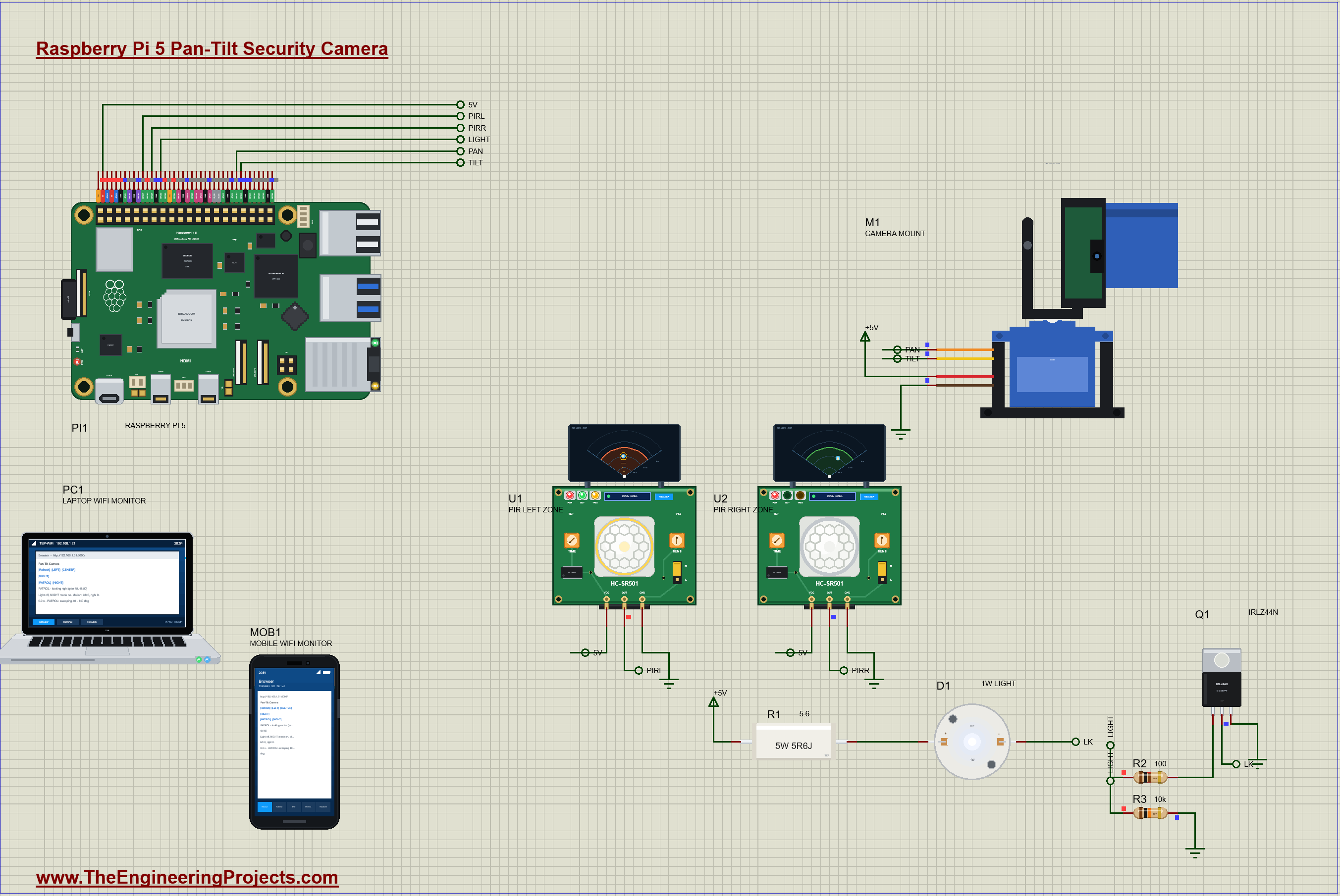
What Does This Pan-Tilt Camera Do?
- Patrols: while nothing moves, the camera sweeps the room from 40 to 140 degrees and back, pausing at each end.
- Tracks motion: a PIR sensor on each side turns the camera to its zone the moment someone walks in.
- Holds, then lets go: it stays on the zone until 6 s after the last motion, then goes back to its patrol.
- Presets: LEFT, CENTER and RIGHT from the dashboard, held for 15 s, then PATROL again.
- Smooth moves: every move is eased to at most 90 degrees a second, so the picture never jerks.
- A night light: a 1 W white LED comes on with the motion and goes off 10 s after the last one.
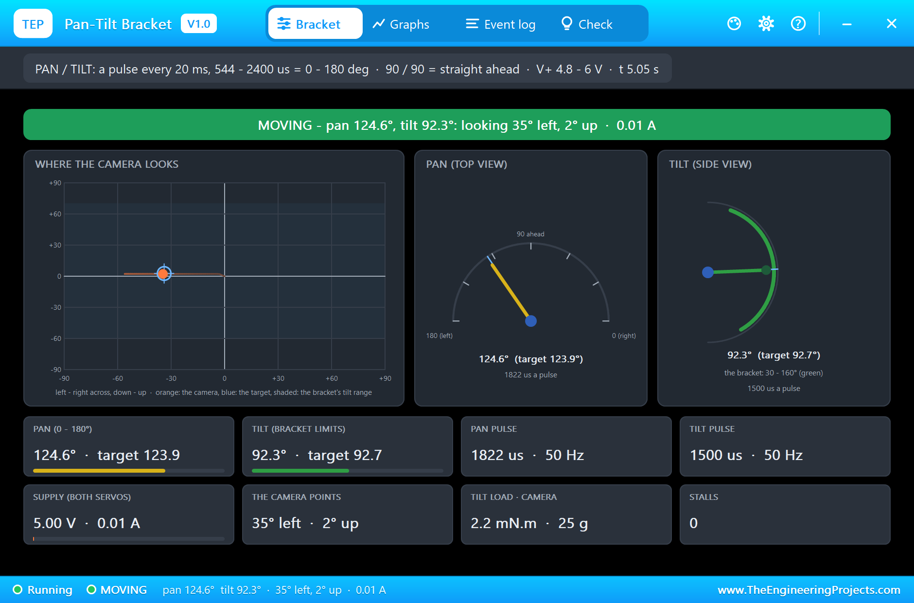
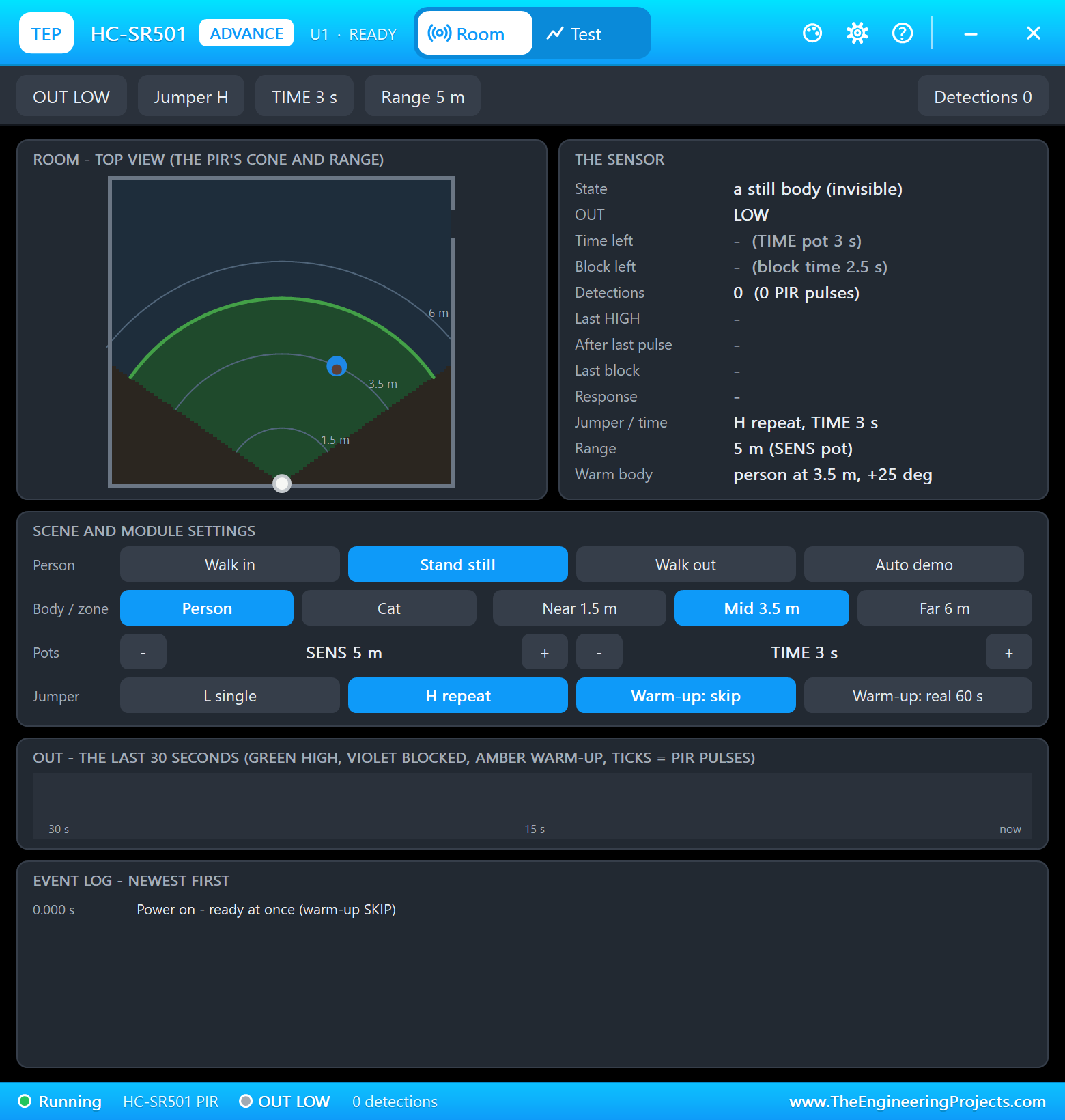
It is a great project for learning servo control, state machines, sensor-driven automation and how to drive a power LED properly. In the simulation, the pan-tilt bracket's pop-up shows where the camera looks from above and from the side, the PIR sensors' pop-ups show the room with the person walking through the detection cone, and the power LED's and the resistor's pop-ups show the current, the power and the heat.
Components Used in the Proteus Simulation
All the parts come from our Proteus libraries, each with its own tutorial. The project zip at the end includes every LIB and DLL file.
| Part | Proteus device | Library post | Connection |
|---|---|---|---|
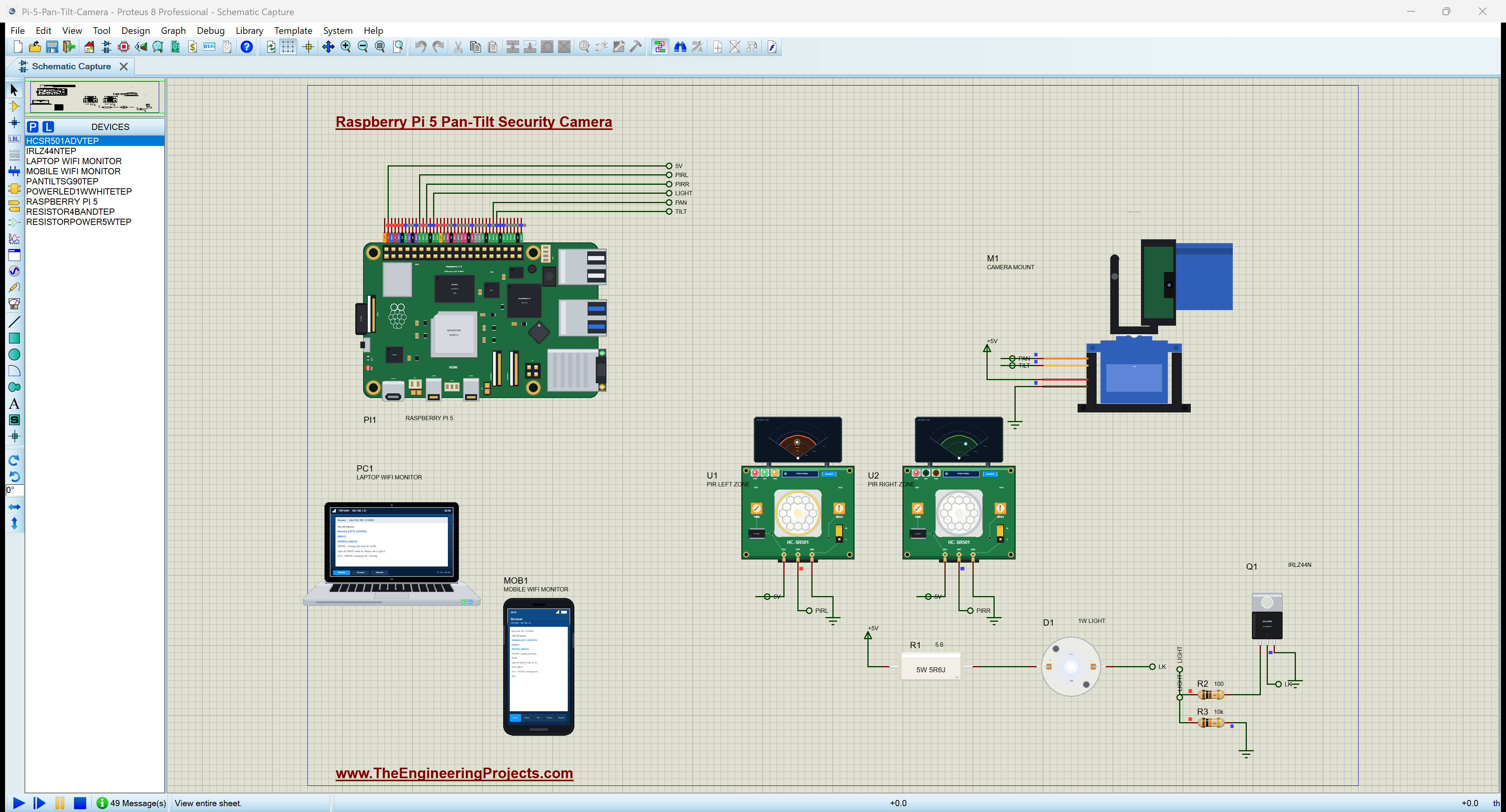
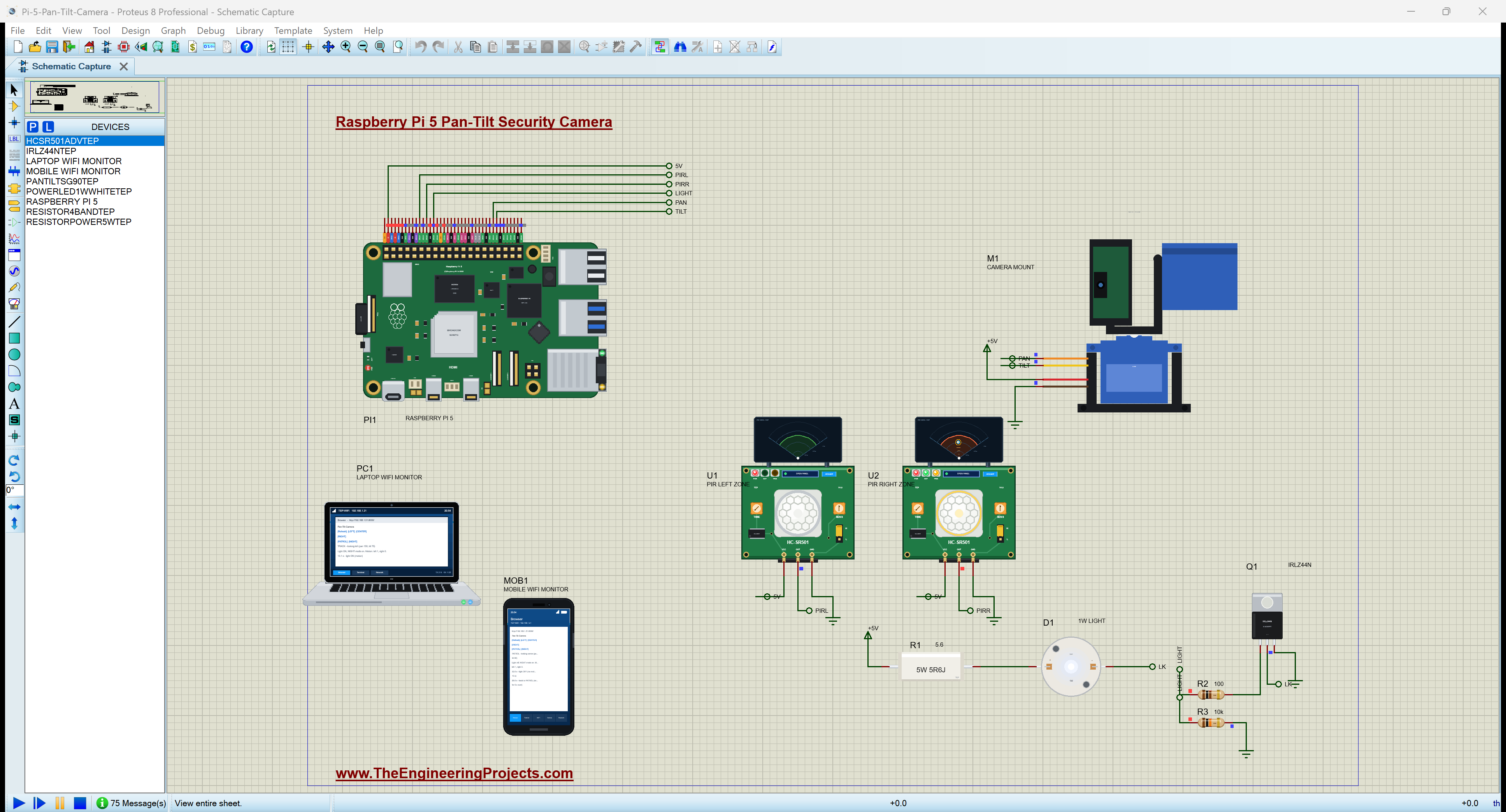
| Raspberry Pi 5 | RASPBERRY PI 5 | Raspberry Pi 5 Library for Proteus | PI1, runs pan_tilt_cam.py, 192.168.1.51 |
| Pan-tilt bracket (two SG90) | PANTILTSG90TEP | Pan-Tilt Bracket Library for Proteus | M1, PAN GPIO12, TILT GPIO13 |
| HC-SR501 PIR sensor x 2 | HCSR501ADVTEP | PIR Sensor Library for Proteus | U1 left zone GPIO17, U2 right zone GPIO27 |
| 1 W white power LED | POWERLED1WWHITETEP | Power LED Library | D1, the light |
| 5 W power resistor 5.6 ohm | RESISTORPOWER5WTEP | Power Resistor Library | R1, the LED's current |
| IRLZ44N MOSFET | IRLZ44NTEP | N-MOSFET Library | Q1, gate GPIO22 |
| Resistors 100, 10k | RESISTOR4BANDTEP | Resistor Library | R2, R3 (the gate) |
| Laptop WiFi Monitor | LAPTOP WIFI MONITOR | Laptop WiFi Monitor | PC1 |
| Mobile WiFi Monitor | MOBILE WIFI MONITOR | Mobile WiFi Monitor | MOB1 |
The pan-tilt bracket carries a 25 g camera on two SG90 micro servos, one turning the whole head left and right, the other tilting the camera up and down. The 5 V supply for the servos and the light is a Proteus power terminal; the PIR sensors take their 5 V from the Pi's 5 V pin, as they would on a real board.
Proteus Simulation of the Pan-Tilt Camera: the Circuit
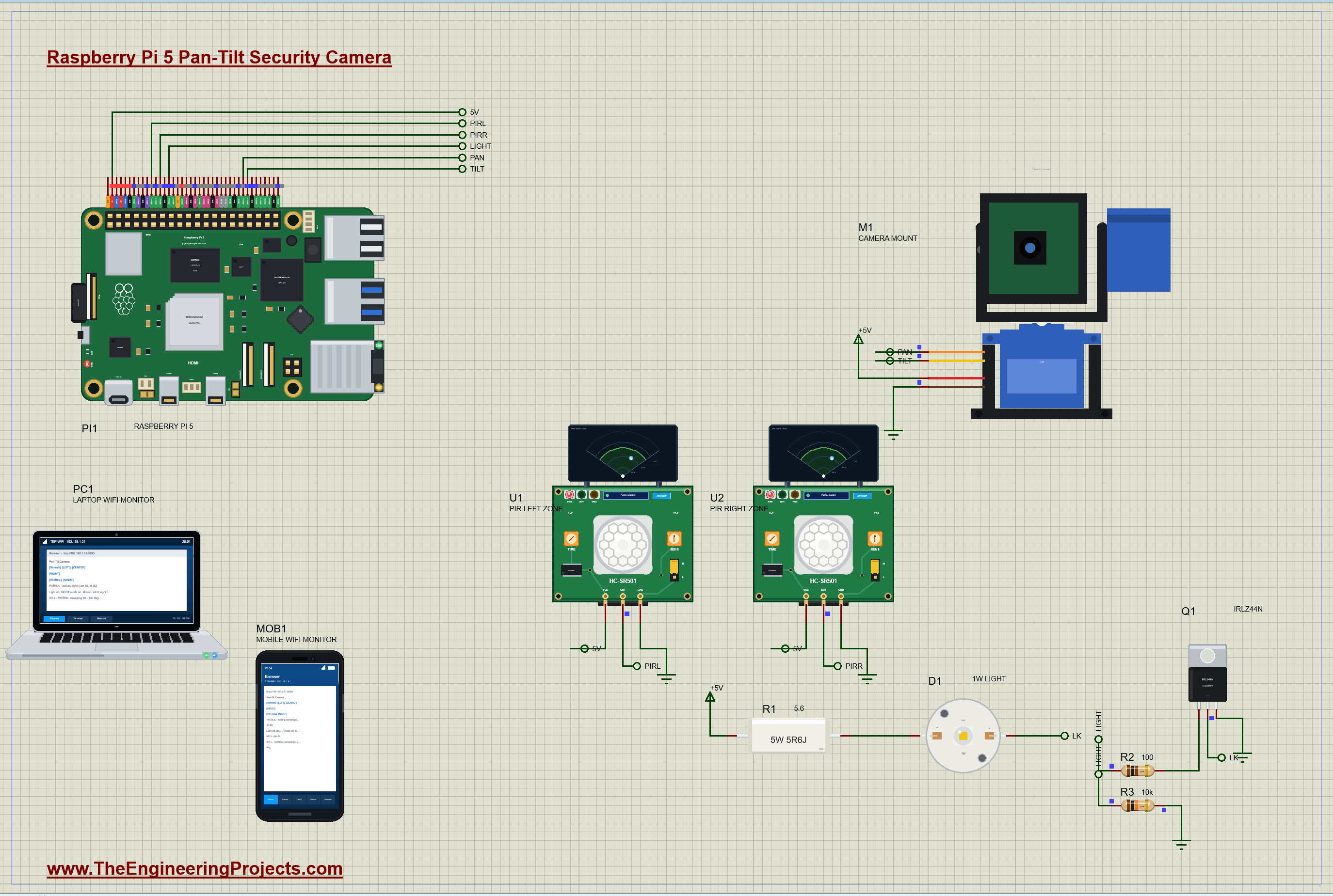
| Part | Pins | Raspberry Pi 5 / other |
|---|---|---|
| M1 pan-tilt | PAN / TILT / V+ / GND | GPIO12 (pin 32) / GPIO13 (pin 33) / +5 V / GND |
| U1 PIR (left) | VCC / OUT / GND | 5 V (pin 2) / GPIO17 (pin 11) / GND |
| U2 PIR (right) | VCC / OUT / GND | 5 V (pin 2) / GPIO27 (pin 13) / GND |
| The light | R1 / D1 / Q1 | +5 V - R1 5.6 ohm - D1 - Q1 drain; Q1 source GND |
| Q1 gate | R2 / R3 | GPIO22 (pin 15) through 100 ohm; 10k to GND |
The servos and the light draw their current from the 5 V rail, never through the Pi's pins: a GPIO only sends the servos their position pulses and switches the MOSFET's gate. The PIR sensors run on 5 V but their output is 3.3 V, so it goes straight to a Pi input. Q1 sits on the light's low side: GPIO22 high turns it on through the 100 ohm gate resistor, and the 10 kohm resistor keeps it off while the Pi boots.
How the Pan-Tilt Camera Works
Positioning a Servo with Pulses
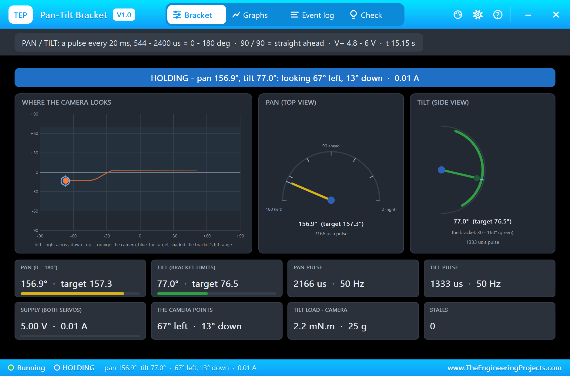
A hobby servo is a small motor, a gearbox and a position sensor with a controller inside. It reads one pulse every 20 ms, 50 a second, and turns to the angle the pulse's width asks for. The Pi times these pulses itself with lgpio's tx_servo, so they stay steady whatever the Python program is doing. The catch is that servos do not agree on the range. Our program uses the common 500 to 2500 microseconds for 0 to 180 degrees; the bracket's SG90s, like the Arduino Servo library, read 544 to 2400. Worked example: the LEFT preset, 150 degrees, is a 500 + 2000 x 150 / 180 = 2166 microsecond pulse, which these servos read as (2166 - 544) / 1856 x 180 = 157 degrees. The camera points 7 degrees further than asked, and the bracket's pop-up shows exactly that. On a real mount you calibrate it: find the pulses for the two ends on your servos and put them in the program.
Eased Moves and the Patrol
A servo sent from one end to the other jumps there as fast as it can, which shakes a camera and blurs the picture. The program never does that: twenty times a second it moves the pan and the tilt towards their targets by at most 4.5 degrees, which caps the speed at 90 degrees a second. Worked example: from the right zone to the centre is 60 degrees, so the camera glides there in two thirds of a second. The patrol is slower still, 20 degrees a second: 40 to 140 degrees takes 5 seconds, plus a 1 second pause at each end, so one full sweep takes 12 seconds.
Watching Two Zones with PIR Sensors
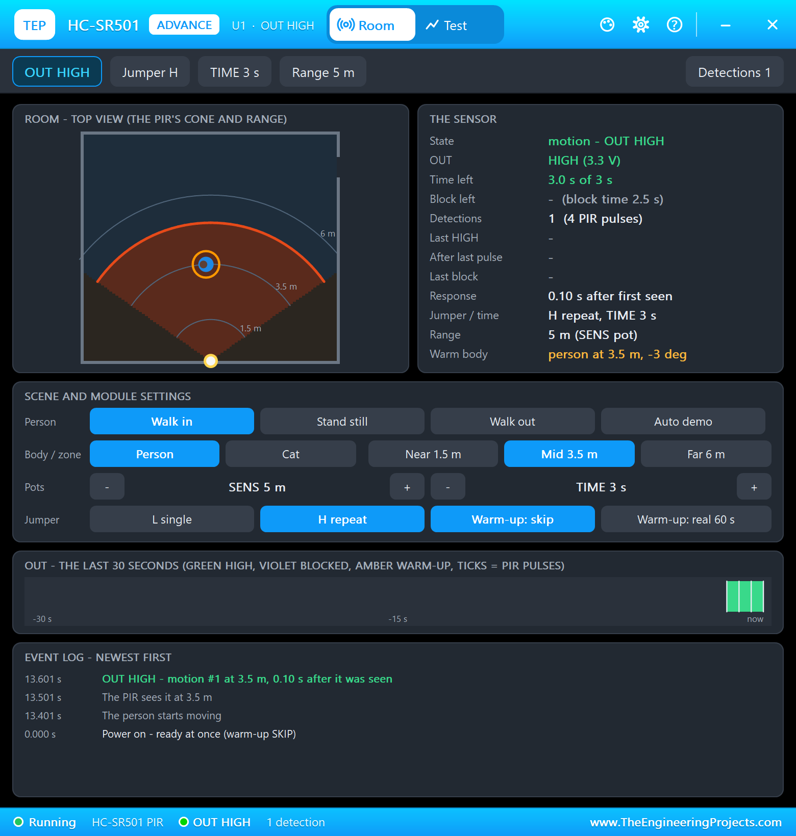
A PIR sensor sees the infrared heat that every warm body gives off. Its Fresnel lens splits the room into many small beams, and its pyroelectric element answers not to warmth itself but to a change: when a person walks from one beam to the next, the signal swings and the sensor's output goes high. A person standing completely still fades out, which is why PIRs are motion sensors, not presence sensors. Our two HC-SR501s each watch one side of the room. In the H (repeat) mode the output stays high while the motion lasts and for TIMEDELAY, 3 s here, after it ends; then a 2.5 s block time follows, during which the sensor ignores everything.
The Modes: PATROL, TRACK and MANUAL
The program is a small state machine. In PATROL the camera sweeps. A rising edge on a PIR's output switches to TRACK and sets the target to that zone's preset, and every moment of motion pushes the end of the hold 6 s further away. When the hold runs out, back to PATROL. A preset from the dashboard switches to MANUAL for 15 s, and the PIRs do not override it, because someone has just chosen where to look. Separate from the modes, NIGHT mode switches the light on with any motion and keeps it on until 10 s after the last one.
Driving a 1 W LED
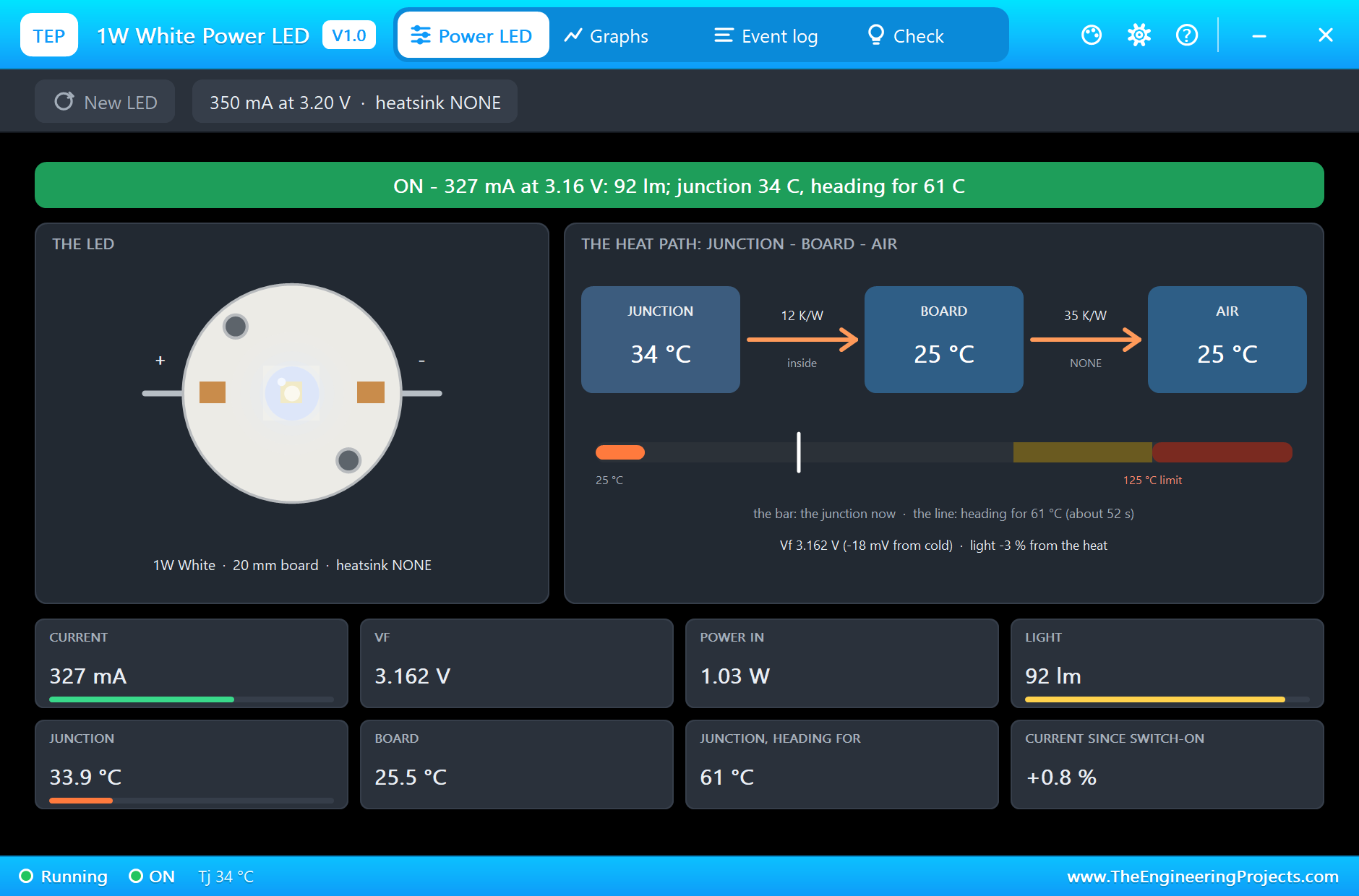
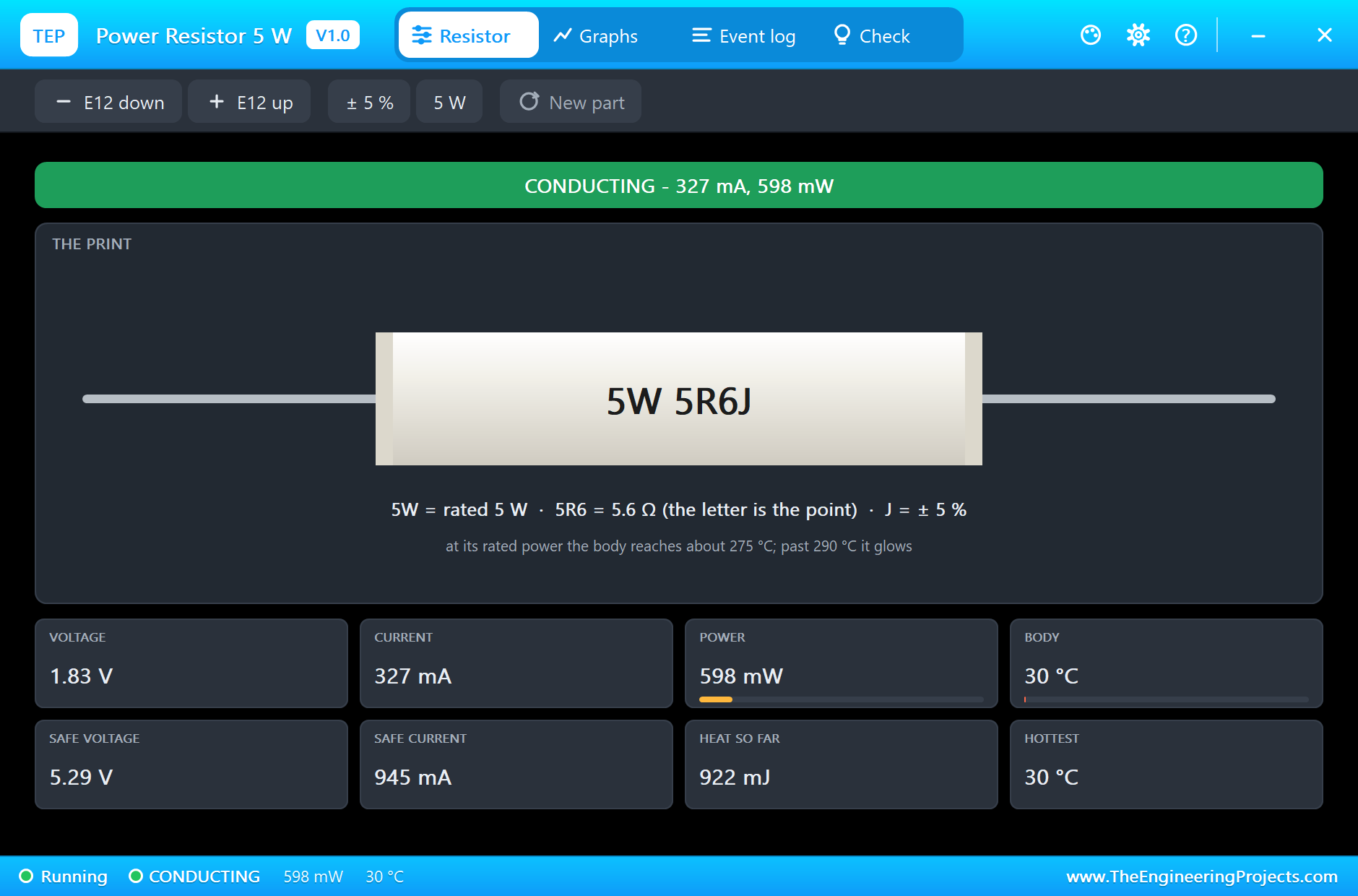
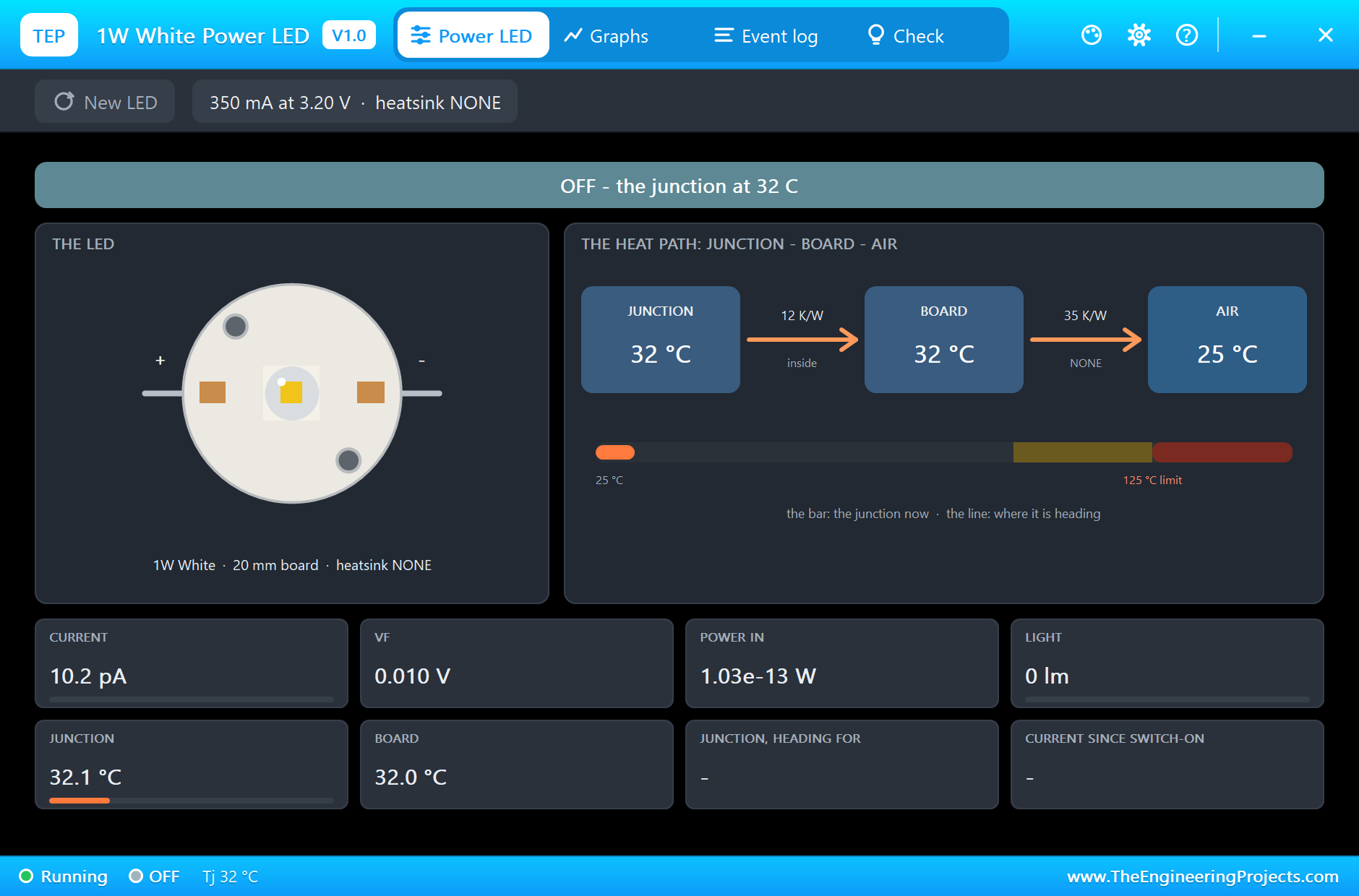
A 1 W white LED needs about 300 mA, far more than a GPIO's few milliamps, and like every LED it needs its current limited, because its voltage hardly changes with the current. On a 5 V rail the resistor takes what the LED does not. Worked example: with the LED at 3.16 V, R1 drops 5 - 3.16 = 1.84 V, and 1.84 V / 5.6 ohm = 0.33 A; the simulation measures 327 mA. The LED takes 3.16 x 0.327 = 1.03 W, and R1 takes 1.84 x 0.327 = 0.6 W, which is why it is a 5 W cement resistor and not a small one. The LED also gets warm. About a quarter of its power leaves as light; the rest has to flow from the junction to its aluminium board and on to the air. With no heatsink, the simulation shows the junction at 34 C and heading for 61 C. A heatsink would keep it much cooler and make it last longer.
The Python Code Explained
The whole program is included in the download. It uses lgpio for the servo pulses, the PIRs and the light, a thread for the control loop and http.server for the dashboard. At the top are the speeds, the sweep and the presets:
SPEED = 90.0                                           # the most a servo turns, degrees a second
PATROL = (40.0, 140.0, 20.0, 1.0)                      # the sweep: from, to, degrees a second, the pause at each end (s)
PRESETS = {'left': (150.0, 75.0), 'center': (90.0, 80.0), 'right': (30.0, 75.0)}   # pan, tilt
TRACK_HOLD, MANUAL_HOLD, LIGHT_HOLD = 6.0, 15.0, 10.0 # secondsThe Servo Pulses and the Easing
Each servo gets its pulse width from its angle; the easing moves each axis at most one step towards its target on every pass of the loop:
lgpio.tx_servo(chip, pin, int(500 + 2000 * deg / 180), 50) s[k] += max(-step, min(step, d))The PIRs and the Holds
Twenty times a second the program reads both PIRs. While a zone sees motion, its TRACK hold and the light's hold keep moving forward:
m = lgpio.gpio_read(chip, pin) == 1 s['until'] = now + TRACK_HOLD s['light_until'] = now + LIGHT_HOLD if mode in ('TRACK', 'MANUAL') and now > s['until']:The patrol turns round when it reaches an end, after its pause:
if now >= pause_until and abs(s['pan'] - sweep_to) < 0.5:The Light
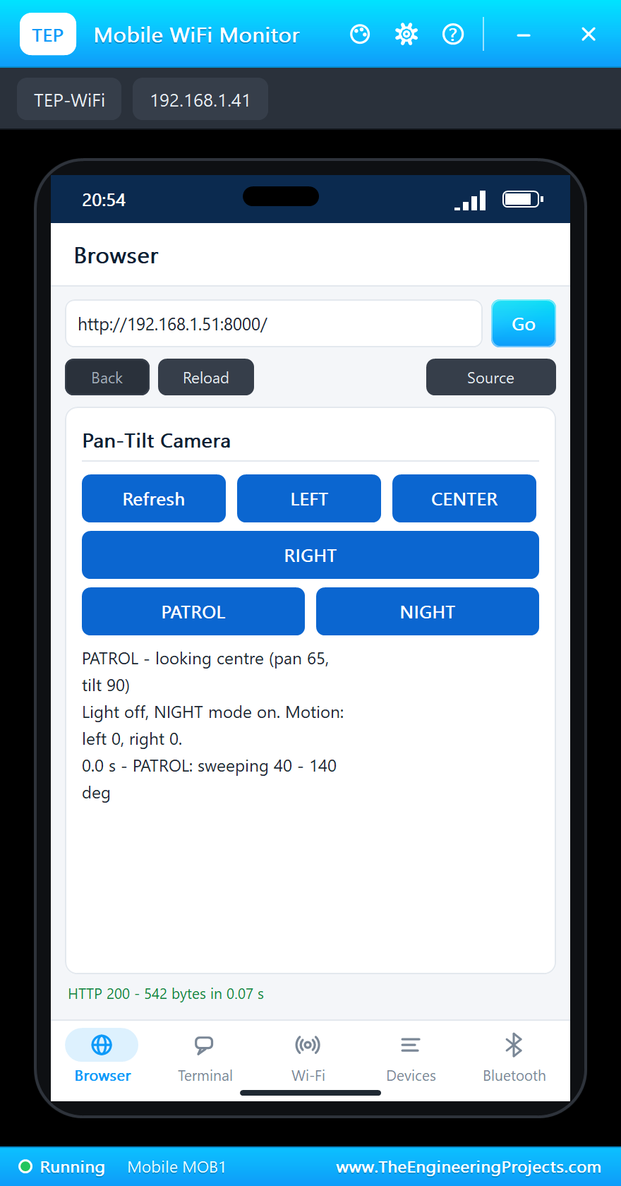
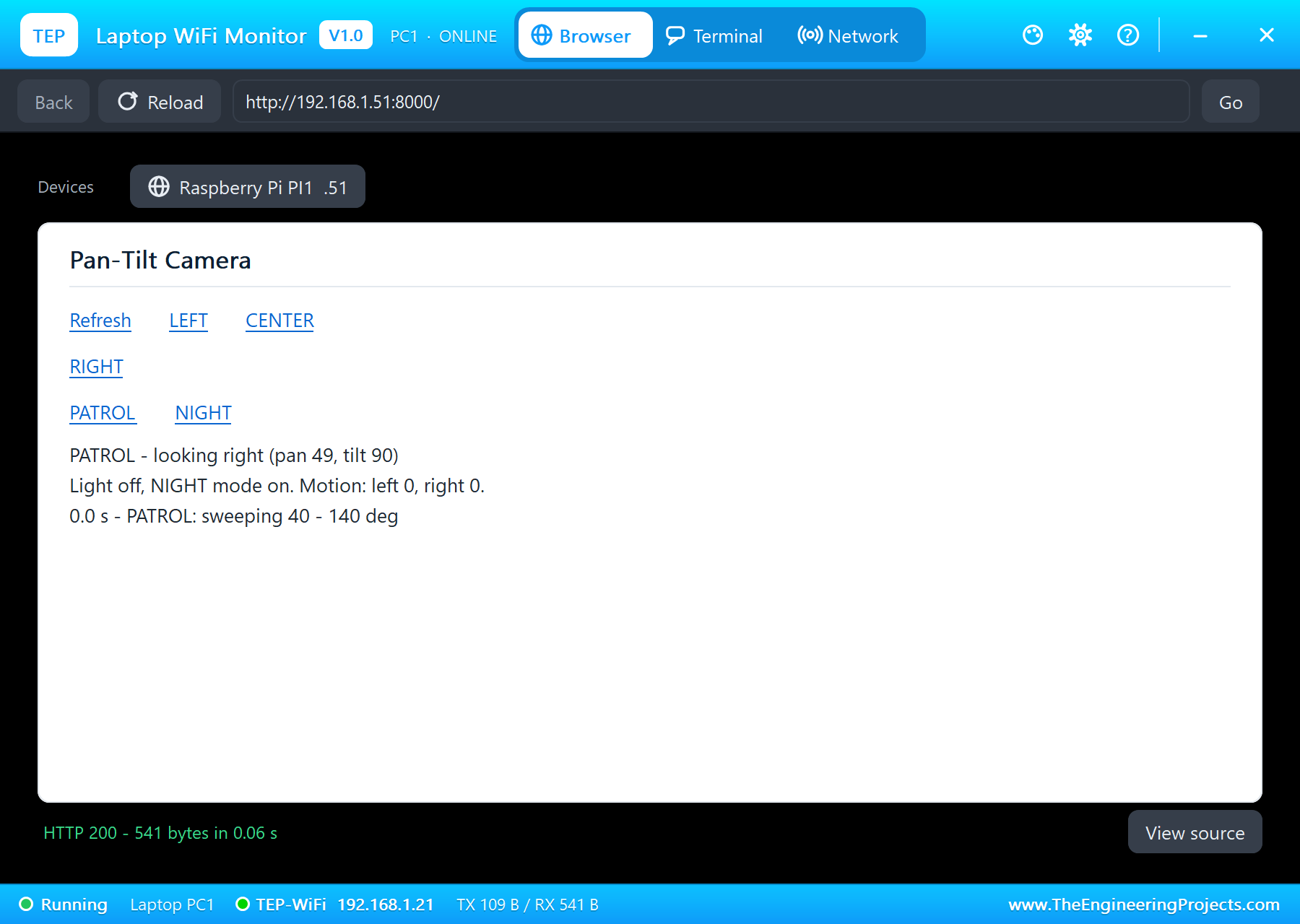
lgpio.gpio_write(chip, LIGHT, 1 if on else 0)The pages are / (the dashboard), /left, /center and /right (the presets), /patrol, /night (NIGHT mode on or off) and /data (JSON). The dashboard puts its links first and stays short, because the WiFi Monitors show one screen of a page.
How to Run the Proteus Simulation
- Download the project zip below and install the library files and the TEPPi folder (the steps are under the download button).
- Open Pi-5-Pan-Tilt-Camera.pdsprj from the Proteus Simulation folder. Keep pan_tilt_cam.py and the DLL files next to it.
- Press Play. The camera starts its patrol and the Pi's terminal prints a line every second.
- Click a PIR for its pop-up and press Walk in: the camera turns to that zone and the light comes on.
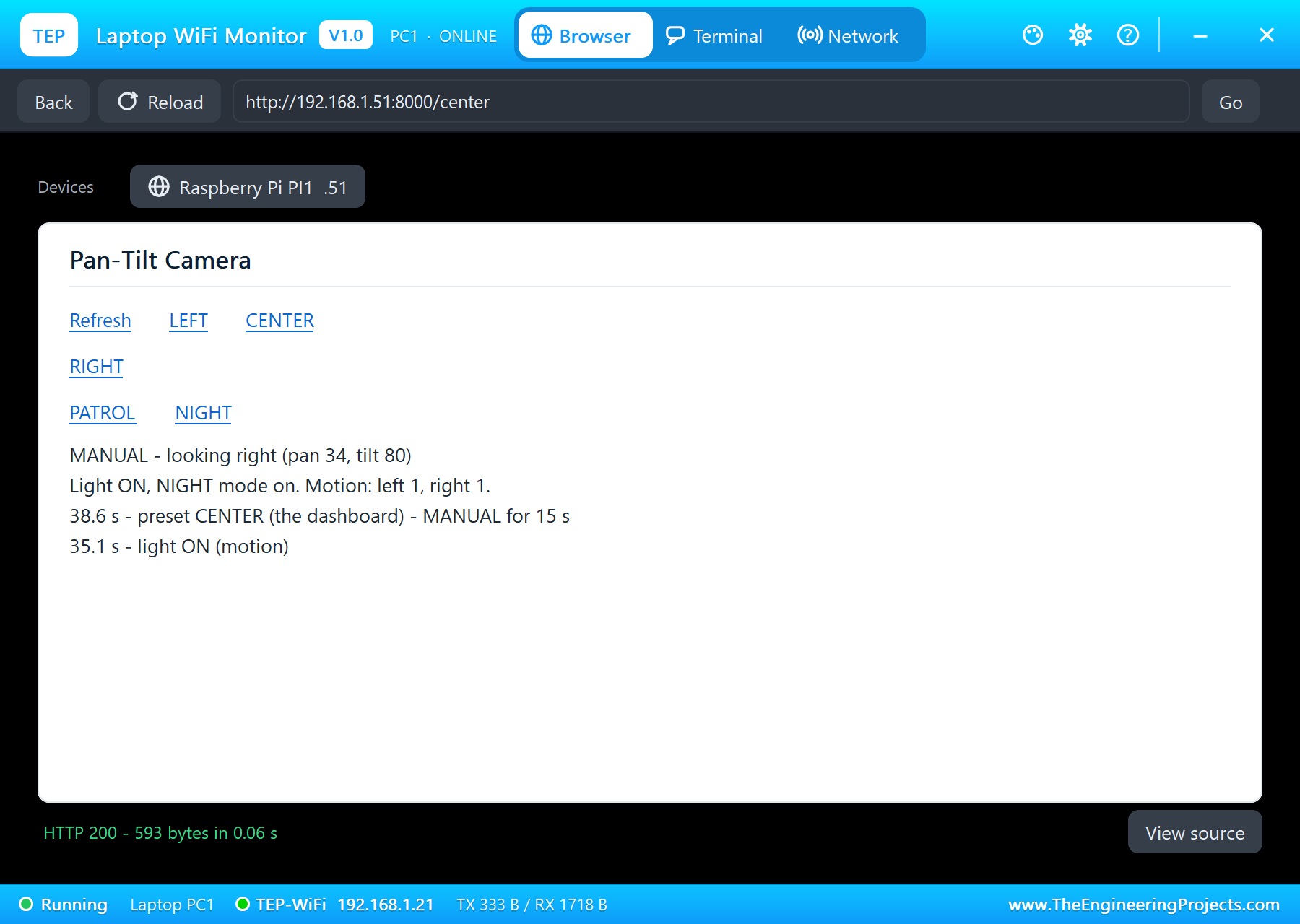
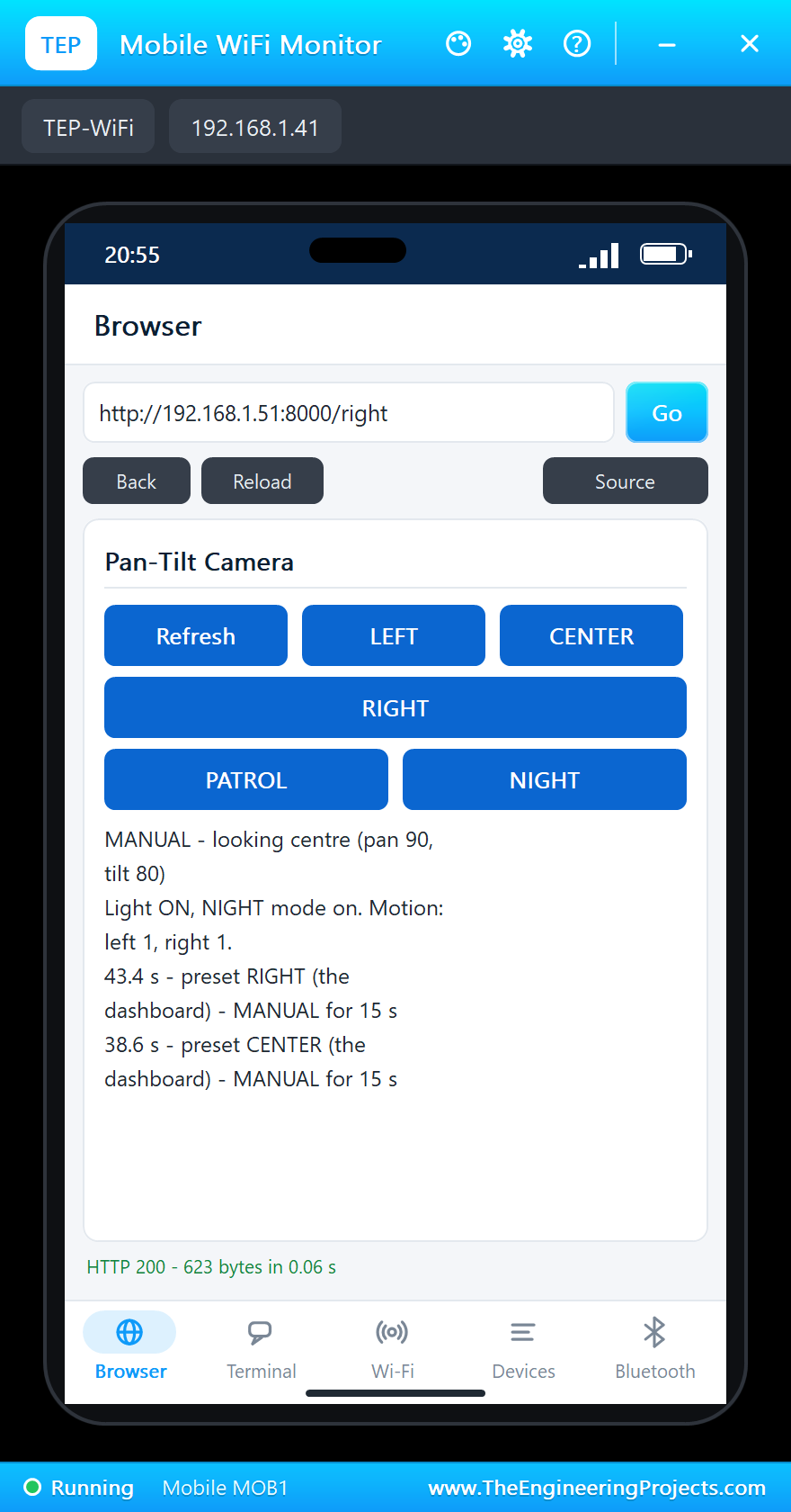
- Open the Laptop WiFi Monitor (PC1) or the Mobile WiFi Monitor (MOB1) and press Go: LEFT, CENTER, RIGHT, PATROL and NIGHT.
Simulation Results: the Pan-Tilt Camera in Proteus
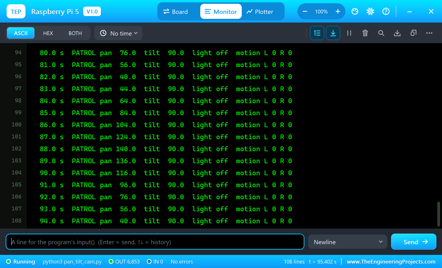
Here is the run that made the screenshots of this tutorial. The times are the program's own, the seconds since it started, as it printed them in the Pi's terminal. The person was moved from the PIRs' pop-ups: into the left zone at 13 s and out again at 18 s, into the right zone at 35 s and out at 42 s.
The Patrol
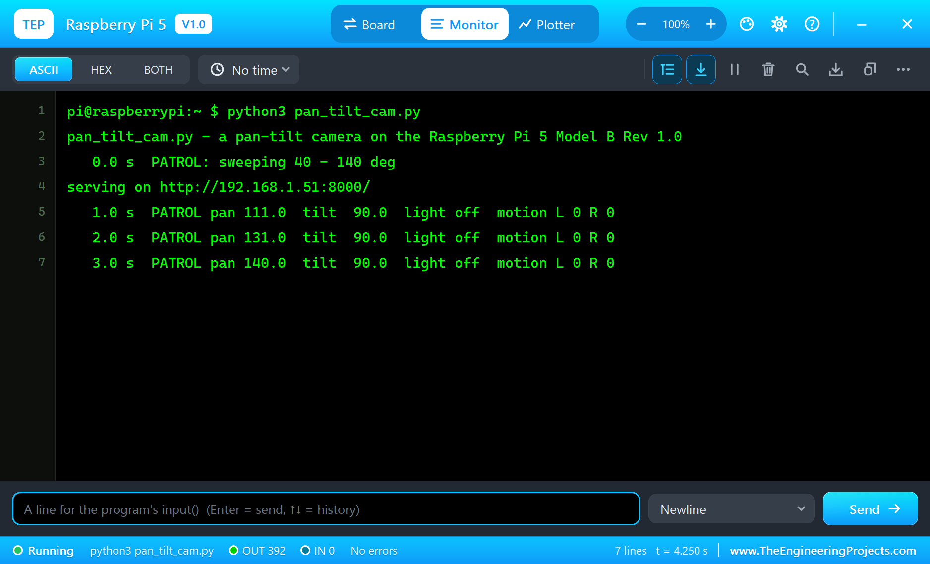
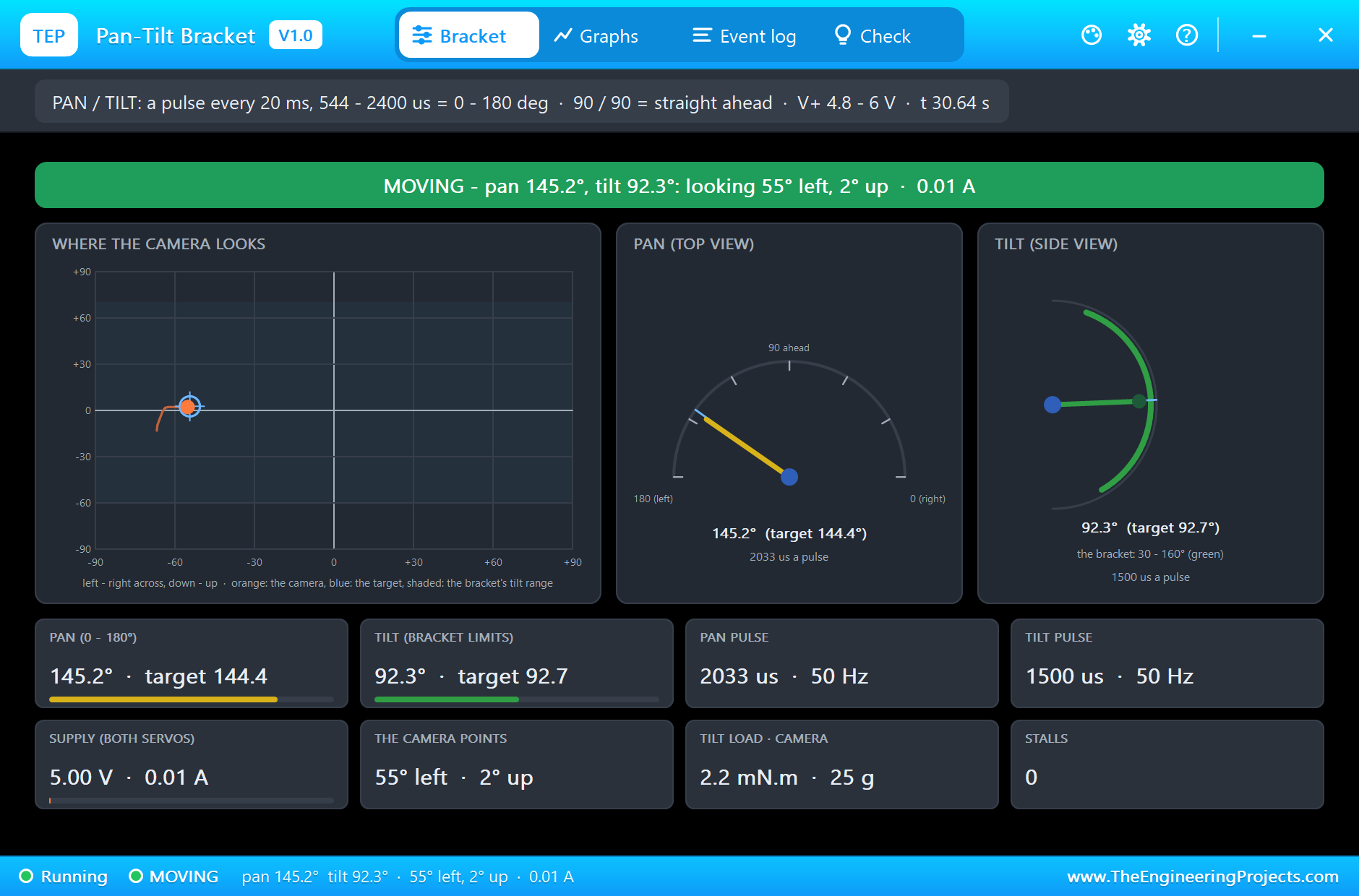
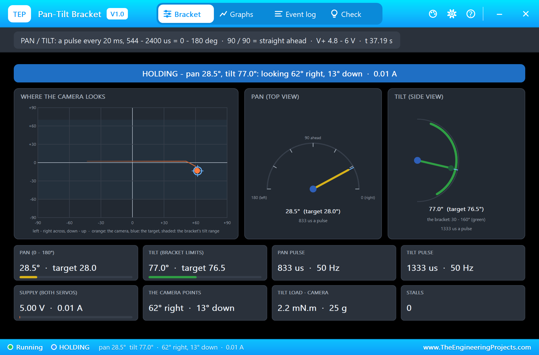
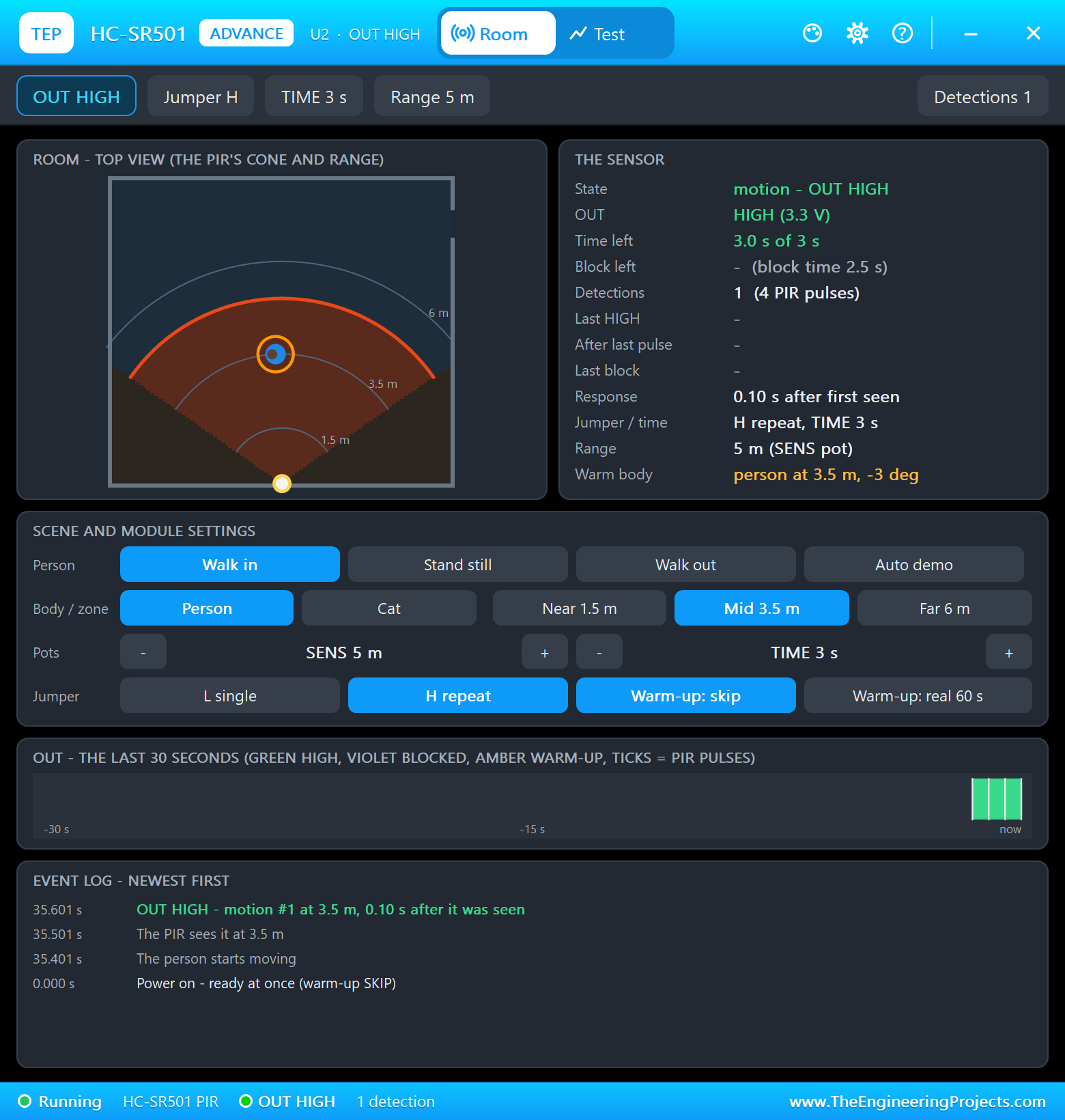
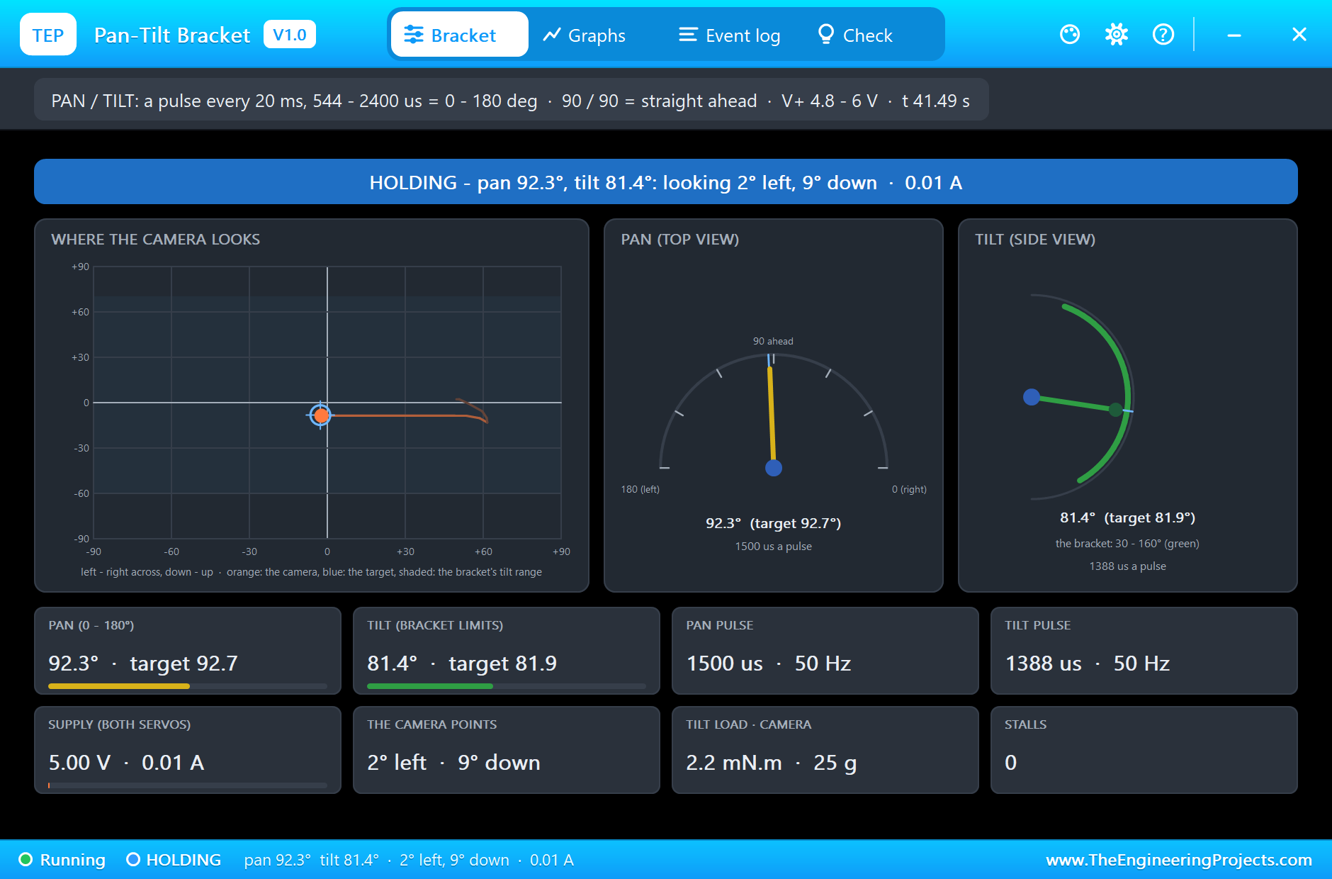
At 0.0 s "PATROL: sweeping 40 - 140 deg". The terminal prints the pan every second: 111, 131 and 140 degrees, a pause, then back down 129, 109, 89, 69 and 49 to 40 degrees at 9.0 s, 20 degrees a second. The bracket's pop-up shows the camera turning with its pan target just ahead of it, the tilt level, and both servos taking only 0.01 A at rest. The PIR's pop-up shows the room quiet: a person standing still, invisible to it.
Someone in the Left Zone
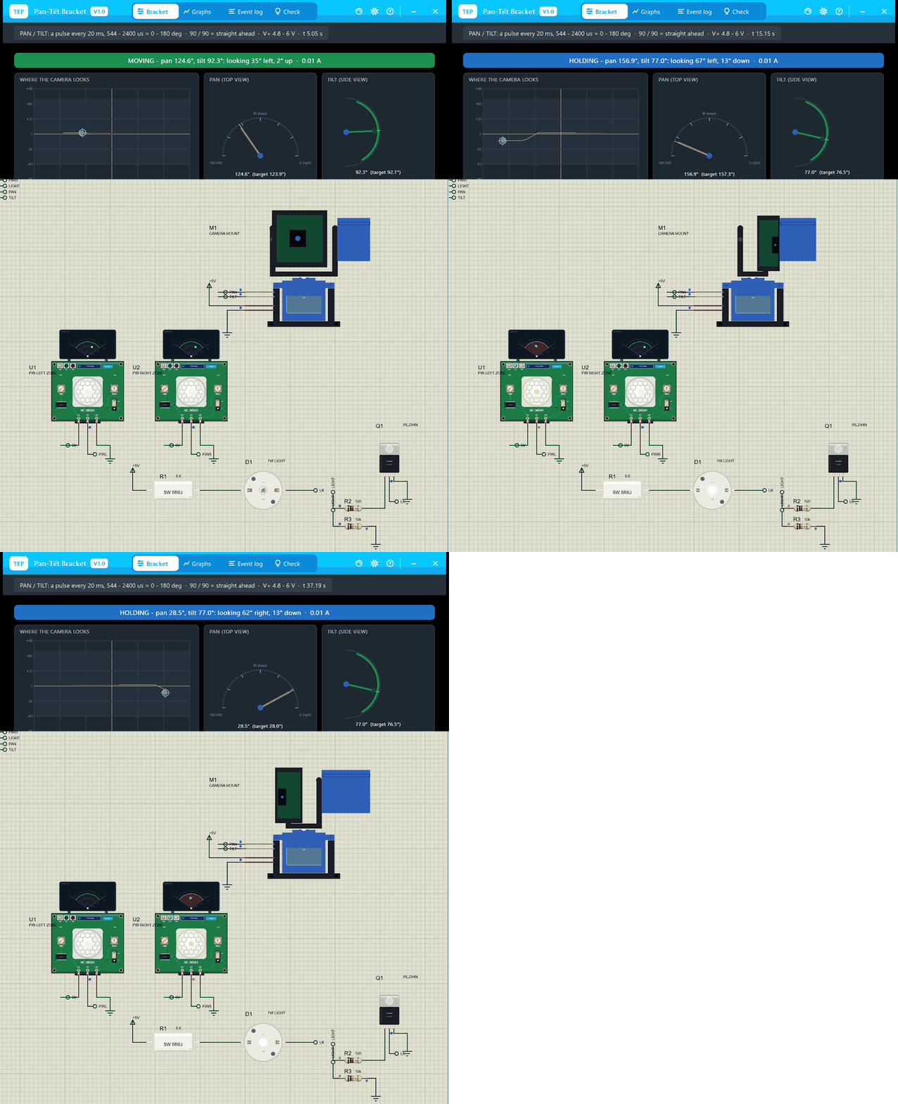
At 13.1 s a person walks into the left zone. The PIR sees them 0.1 s later, and the program answers at once: "motion LEFT (1) - the camera turns left" and "light ON (motion)". In under half a second the camera is on the left preset, tilted down to watch the floor. The bracket's pop-up shows it at 156.9 degrees, the 157 the 2166 microsecond pulse means to these servos. The light draws 327 mA at 3.16 V, 1.03 W and 92 lumens, and its junction is at 34 C and climbing towards 61 C. The resistor takes 1.83 V and 598 mW, comfortably inside its 5 W.
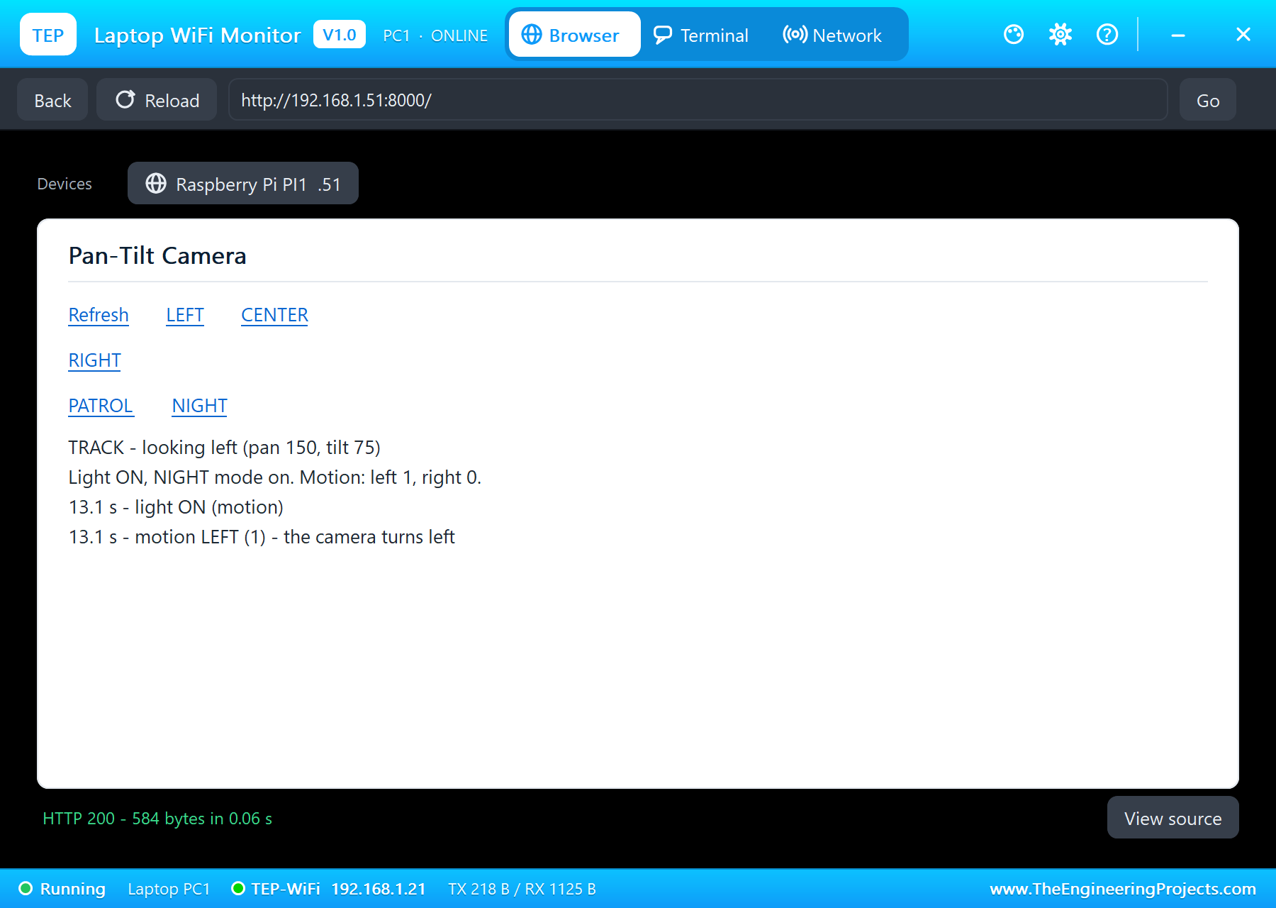
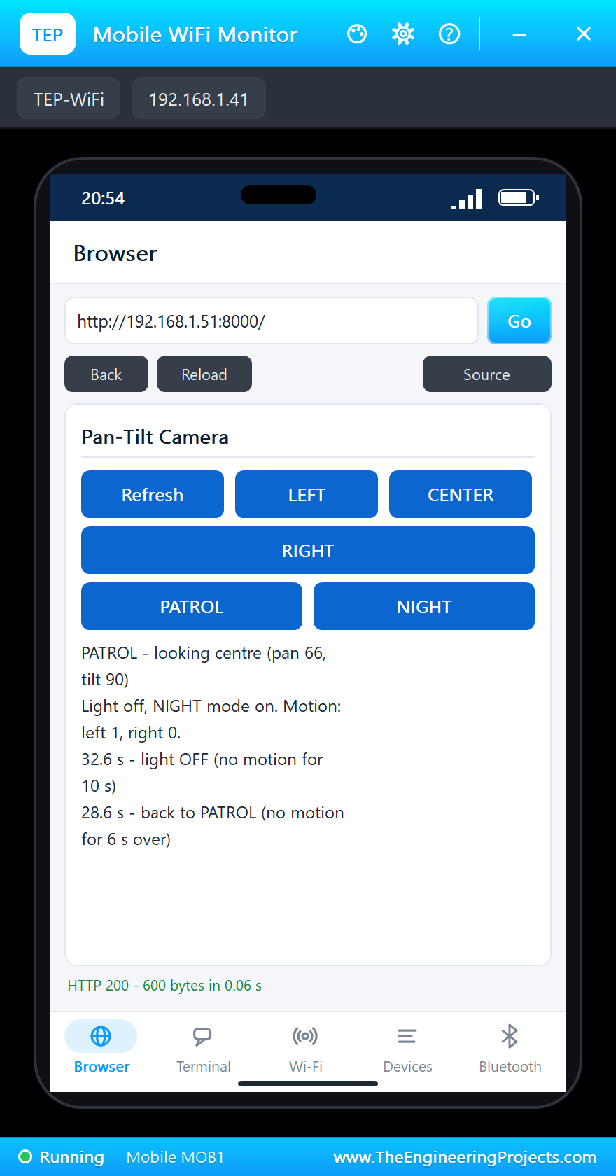
The person walks out at 18 s; the PIR stays high a little longer and its TIMEDELAY adds 3 s, so the last motion is at 22.6 s. Six seconds later, at 28.6 s, "back to PATROL (no motion for 6 s over)", and the camera glides back into its sweep. At 32.6 s, ten seconds after the last motion, "light OFF (no motion for 10 s)".
The Right Zone and Two Presets
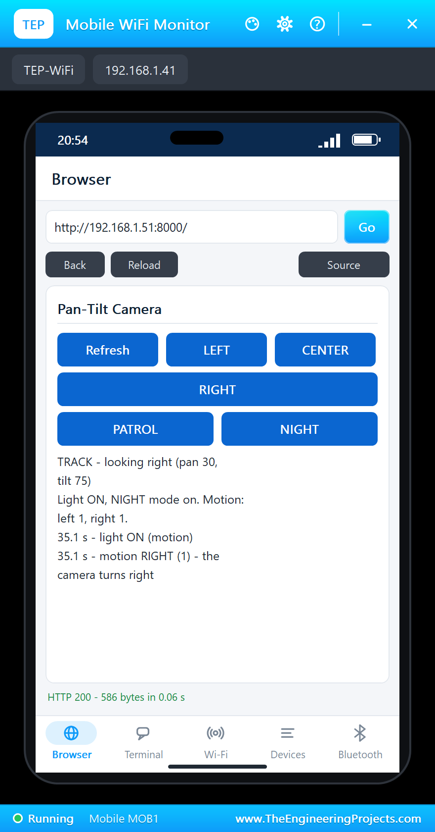
At 35.1 s someone walks into the right zone: "motion RIGHT (1) - the camera turns right" and the light is on again. The camera turns to 28.5 degrees and tilts down. At 38.6 s CENTER on the laptop: "preset CENTER (the dashboard) - MANUAL for 15 s", and the camera glides from the right to the centre, 60 degrees, in about two thirds of a second, even though the right PIR still sees motion: a chosen preset is not overridden. At 43.4 s RIGHT on the phone, MANUAL again. When the person has gone and the light's 10 s are over, "light OFF" at 56.1 s, and at 58.4 s "back to PATROL (the preset's 15 s over)".
The Numbers of the Run
| What | Result |
|---|---|
| Patrol | 40 - 140 degrees at 20 degrees a second, a 1 s pause at each end |
| Left zone | motion at 13.1 s, the camera at 157 degrees, back to PATROL at 28.6 s |
| Right zone | motion at 35.1 s, the camera at 28.5 degrees |
| Presets | CENTER at 38.6 s, RIGHT at 43.4 s, PATROL again at 58.4 s |
| The light | 327 mA, 1.03 W, 92 lm; off 10 s after the last motion |
| R1 | 1.83 V, 598 mW in a 5 W resistor |
Download the Project Files
Click the button below to download Raspberry-Pi-5-Pan-Tilt-Camera-Motion-Tracking-Proteus-Simulation-v1.0.zip (about 14.7 MB, without the source code of the models):
Raspberry Pi 5 Motion-Tracking Pan-Tilt Camera in Proteus Simulation V1.0- Proteus Simulation: Pi-5-Pan-Tilt-Camera.pdsprj, the program pan_tilt_cam.py and copies of the models.
- Python Code: pan_tilt_cam.py, the complete program.
- Proteus Library Files: the LIB files of the Raspberry Pi 5, the pan-tilt bracket, the PIR sensor, the power LED, the power resistor, the MOSFET, the resistor and the two WiFi Monitors.
- Proteus Model Files: the DLL models and the TEPPi folder, the Python 3.11 and the runtime that the Pi board runs.
- README.txt: the installation steps, the properties, the test results and the links to every library post.
No Proteus yet? Read How to Download and Install Proteus 7 and 8. New to libraries? Follow How to Install a New Library in Proteus.
How to Install the Project Files
- Close Proteus and extract the whole zip file, for example to your Desktop.
- Copy the files from Proteus Library Files into the LIBRARY folder of Proteus.
- Copy everything in Proteus Model Files, the DLL files and the TEPPi folder, into the MODELS folder.
- Start Proteus and open the project from the Proteus Simulation folder.
Changing the Code
The program is plain Python 3: edit pan_tilt_cam.py beside the project and press Play again; the Pi board runs the new file. The speeds, the sweep, the presets and the holds are at the top, and the pulse range is in servo(). The same program runs on a real Raspberry Pi 5 with Raspberry Pi OS and lgpio. For our other Pi 5 security project, with a PIR, a radar sensor, a keypad and an alarm, see the Raspberry Pi 5 Home Security System.
Ideas to Extend the Project
- Add a real camera and take a picture each time a zone triggers.
- Use more PIR sensors for more zones, or a radar sensor that sees through thin walls.
- Add a light sensor so the night light comes on only when it is dark.
- Let the dashboard nudge the camera a few degrees at a time, like a joystick.
- Log every motion with its time and zone, and show a day's activity.
- Calibrate the servo pulses from the dashboard and save them.
From Simulation to Real Hardware
- Power the servos separately: two SG90s can draw over 1 A when they start or stall; give them their own 5 V supply with a common ground.
- Calibrate the pulses: find each servo's real end points and use them instead of 500 and 2500 microseconds.
- Mind the PIR's warm-up: a real HC-SR501 needs about a minute after power-up before it is reliable; the simulation skips it.
- Give the LED a heatsink: at 1 W the bare 20 mm board gets hot; a small heatsink keeps the junction well below its limit.
- Use a constant-current driver for brighter lights: a resistor is fine at 1 W, but a 3 W LED wastes too much in it.
Troubleshooting
- The camera does not move: no 5 V on the bracket's V+, or PAN and TILT not on GPIO12 and GPIO13.
- The camera turns the wrong way: pan 0 degrees looks right; for a bracket mounted the other way round, swap the LEFT and RIGHT presets.
- A PIR never triggers: it has no 5 V; take VCC from the Pi's 5 V pin.
- The light never comes on: NIGHT mode is off, or Q1's gate is not driven from GPIO22.
- The terminal cannot start Python: the TEPPi folder is not in MODELS.
Limitations of the Simulation
- The person is moved from the PIR's pop-up; a real room has many people, pets and heaters that a PIR also sees.
- There is no camera image: the bracket's pop-up shows where the camera points.
- The PIRs' warm-up is skipped (WARMUP SKIP) so they work from the first second.
- The network is simulated: the dashboard travels between the Pi and the two monitors inside Proteus; the times in this tutorial are simulation time.
- Raspberry Pi is a trademark of Raspberry Pi Ltd. This project is not made or endorsed by them or by Labcenter.
So, that was all about the Raspberry Pi 5 Motion-Tracking Pan-Tilt Camera in Proteus Simulation. I hope it helps you understand how servos are positioned and why their pulses must be calibrated, why a camera should glide rather than jump, how a PIR sensor sees a person, how to build a little state machine of patrol, track and manual, and how to size a resistor and a MOSFET for a power LED, all tested in a simulation before you mount a single real camera. More IoT projects with the ESP32 and the Raspberry Pi 5 are coming in this series. If you have any questions, ask in the comments and I will help you out. Till the next tutorial, take care and have fun!