Current Sensor Library for Proteus

Hi Friends! Hope you’re well today. Today, I am going to share the Proteus Library of Current Sensor WCS1600. This sensor is not available in the Proteus Components Library and we’re sharing it for the first time.

The Current Sensor WCS1600 is used to measure the current flowing through the circuit and is used in embedded systems and robotics projects. If you are new to this sensor, you must first design its simulation before playing with the hardware. 

Before we move further, let’s have a brief overview of WCS1600 Current Sensor:

Where To Buy?
No.ComponentsDistributorLink To Buy
1LEDsAmazonBuy Now
2ResistorAmazonBuy Now
3ACS712AmazonBuy Now

What is WCS1600 Current Sensor?

WCS1600 comes with a drift linear hall sensor IC which gives precise and accurate values. The hall sensor IC is 9.0 mm in diameter through the hole and is incorporated with a temperature compensation circuit. To measure the passing current, the electric wire of the system should pass through the hole of this sensor.

Using this design, the system designers can monitor the current path of any length without affecting the layout of the original system. The integrated hall IC senses the magnetic field generated when current flows through the wire. That magnetic field is then converted into a proportional voltage.

Features:

  • Product: WCS1600 current sensor.
  • Sensitivity: 22mV/A
  • Low operating current: 3mA
  • Supply Current: 3.5 ~ 6mA
  • Zero Current Vout: 2.5V
  • Bandwidth: 23kHz
  • Isolation voltage: 4000V
  • Supply Voltage: 3 ~ 12V
  • Operating Temp: -20 ~ 125°C
  • Conductor Through Hole: 9.2mm
  • Temperature Drift: +/-0.3 mV/C
  • Output voltage proportional to AC and DC
  • Wide sensing current range 0~100A at 5V volt
  • For easy soldering on PCB, two bronze sticks are used
  • Ratiometric output from the supply voltage

WCS1600 Current Sensor Library for Proteus

  • First, download the Proteus Library zip file for WCS1600 Current Sensor by clicking the link below:

WCS1600 Current Sensor Library for Proteus

Adding Library Files

  • After downloading this zip file, extract it and you’ll find the folder "Proteus Library Files".
  • In this folder, 3 Proteus Library files are available, named:
    • WCS1600TEP.HEX
    • WCS1600TEP.IDX
    • WCS1600TEP.LIB
  • Copy these files and paste them into the Library Folder of Proteus Software, as shown in the below figure:

  • After adding these files to the Library folder, open the Proteus Software, and if you’re already working on it, you need to restart it. 

Note: You should read How to Add Library in Proteus 8, if you are having any issues finding the Library Folder.

Current Sensor in Proteus

In the components section, write ‘WCS1600 Current Sensor’ in the search bar and you’ll get the following result:

Now place this sensor in the Proteus workspace, as shown in the below figure:

You can see in the above figure, this current sensor carries 4 pins as follow:

  • Vcc: 5V is provided to this pin.
  • GND: This pin is grounded.
  • D0: This is the output pin and it goes HIGH when current passes through the hole and will remain LOW when there is no current.
  • A0: This pin will give the analog output.
  • TestPin: As we can't use a current wire in Proteus, so we placed this test pin to indicate current. When this pin is HIGH, means the current is passing through the IC and if it's LOW, means no current. 

Adding Hex File

Now double-click the sensor to open up its Properties Panel, as shown in the below figure:

Go to the ‘Program File’ section and browse for the file WCS1600TEP.HEX which you have already downloaded and placed in the Library Folder of Proteus.

Simulate Current Sensor

  • Now we’ll design a simple circuit to use this WCS1600 Current Sensor in Proteus.
  • The following figure shows the WCS1600 Current Sensor Simulation in Proteus.

  • As you can see in the above figure, I have placed an LC circuit at the analog pin, that's only for the simulation to get the analog value. It won't be used in real hardware.
  • Now run Proteus Simulation. You’ll get the result as shown below.


That’s all for today. Hope you’ve found this Library for Proteus useful. If you’re unsure or have any queries regarding the simulation of this sensor and how to use it in your engineering projects, you are welcome to get in touch with me in the section below. I’ll help you the best way I can. Thank you for reading this tutorial.

pH Sensor Library for Proteus

Hi guys, I hope you are good and doing well in your life. In this article, I am going to tell you about a new pH Sensor Library for Proteus. I hope you all will enjoy it and find it useful. We are all well aware of pH Sensors which are used for the detection of pH of different fluids. By knowing the pH of a liquid we can tell whether the liquid is acidic or basic. You can’t find a pH sensor in Proteus software, so we designed a pH sensor for simulation purposes. You can interface this pH Sensor with any Microcontroller, for example: Arduino, PIC Microcontroller, 8051 Microcontroller etc.

In this pH Sensor Library, I have added four different pH Sensors, which are used for the detection of the pH of any fluid. Since we can’t place real liquid and measure pH in this software, I have attached a test pin in the pH meter where you have to connect a potentiometer. The potentiometer will produce a reading from 0 to 1023, which will be mapped from 0 to 14 in the program code. We can predict the nature of the liquid. We will have a look at how to use these sensors below. So, here’s the list of all four pH sensors, I have added to this pH sensor  library:

  • PH METER
  • PH METER 2
  • PH METER 3
  • PH METER 4

So, let’s start with downloading and installing the pH Sensor Library for Proteus.

Where To Buy?
No.ComponentsDistributorLink To Buy
1LEDsAmazonBuy Now
2ResistorAmazonBuy Now
3Arduino UnoAmazonBuy Now

What is a pH Sensor?

  • A pH sensor is a device that is used to measure the pH value of a liquid. pH can be defined as the concentration of H+ ions in a liquid. We can find whether the fluid is acidic, basic or neutral by knowing the pH of the liquid.
  • Real pH sensors are shown below:

pH sensor Library for Proteus

  • First, download the zip file of Proteus Library for pH Sensor.
  • Click the link below to download the library zip file of pH Meter:
pH Sensor Library for Proteus
  • After downloading the zip file, extract its files and open the folder named “Proteus Library Files“.
  • In this folder, you will find three files, named:
    • pHMeterLibraryTEP.IDX
    • pHMeterLibraryTEP.LIB
    • pHMeterLibraryTEP.HEX
  • We have to place these files in the ‘LIBRARY’ folder of Proteus software.
  • Now, open Proteus. if you are already working on it you have to restart it.
  • In the components search box, search for “PH METER” and you will get four results, as shown in the below figure:
  • Let’s place these four pH Meter models in our Proteus workspace:

Adding Hex File to the Sensor

  • Now we need to paste the hex file of the pH METER in the properties section of the sensor. Double click on the sensor to open the properties window.
  • Go to the program file section, browse to the hex file, which we have downloaded above and placed it in the ‘LIBRARY’ folder of Proteus software:
  • After adding the hex file, click the Ok button.
  • Now all is ready, let’s create a circuit to check it's working.

pH Sensor Proteus Simulation

  • The pH sensor is now ready to simulate in Proteus, so let’s design a simple circuit to understand its working:
  • As you can see, I have placed an LC filter on the analog output of the pH sensor, it's because proteus gives us a peak to peak voltage value and we need to convert it to Vrms.
  • While performing the real experiment, you don’t need to do the above stuff.
  • Now, let’s run the Proteus simulation. You will see such a screen if everything will work fine.

Interfacing of pH sensor with Arduino UNO

  • Add Arduino UNO  and pH sensor to the components list and place them in the workspace.
  • Placed an LC filter on the analog output of the pH sensor, as mentioned above.
  • Connect it to the A0 pin of Arduino. Add a virtual terminal also to see the readings generated.
  • Paste the hex file of the program at the program file section of the Arduino.
  • Now run the simulation, if everything's fine you will get results as shown in the below figure:
  • You can watch the complete working simulation in the below video:

So, that was all for today. I hope you have enjoyed today's lecture. Thanks for reading !!!

Latest Proteus Libraries for Engineering Students V2.0

Hi Friends! Hope you’re well today. Happy to see you around. In this post today, I’ll walk you through Latest Proteus Libraries for Engineering Students V2.0.

We have been designing proteus libraries for our blog readers for quite a while now. You might have visited our Arduino Libraries for Proteus V2.0 and Analog Sensors Libraries for Proteus V2.0. We keep working on those libraries and make sure the bugs are removed and you always get the updated version of those libraries.

We are going to share the most advanced and upgraded version of Proteus Libraries V2.0 we have designed for our readers. These libraries are more robust, fast, and efficient than previous versions. Moreover, we have converted some digital sensors to analog sensors, helping you pick from a wide range of libraries for your projects. If you think some sensors or modules are missing in the Proteus database that should be included, leave your valuable suggestion in the section below. We’ll try our best to design and simulate those in proteus.

Before further ado, let’s jump right in.

Where To Buy?
No.ComponentsDistributorLink To Buy
1LEDsAmazonBuy Now
2ResistorAmazonBuy Now
3ACS712AmazonBuy Now
4DHT11AmazonBuy Now
5DHT22AmazonBuy Now
6DS18B20AmazonBuy Now
7Flame SensorsAmazonBuy Now
8Arduino Mega 2560AmazonBuy Now
9Arduino NanoAmazonBuy Now
10Arduino UnoAmazonBuy Now

Latest Proteus Libraries for Engineering Students V2.0

We’ll be covering both Arduino Libraries for Proteus V2.0 and Analog Sensors Libraries for Proteus V2.0.

Arduino Libraries for Proteus V2.0

Arduino boards are open-source electronic development boards that you can use in your projects. Arduino Libraries for Proteus V2.0 contain the following Arduino boards.

1. Arduino UNO Library for Proteus V2.0

Arduino UNO is a microcontroller board based on the Atmega328 microcontroller. We have designed Arduino UNO Library for Proteus V2.0 which you can download from the link given below. We’ve previously designed the Proteus Library for the Arduino UNO V1.0 board and the below figure shows the comparison of both V1 and V2 Arduino boards. You can see the V2 board is more compact and small-sized compared to the V1 Arduino UNO board.

In this library, we’ve also interfaced LCD with the Arduino UNO. If you find any difficulty in interfacing the board with the LCD, you can approach me in the section below. I’d love to help you the best way I can.

Download the Arduino UNO Library for Proteus V2.0 by clicking the link below:

Download Arduino UNO Library for Proteus V2.0

2. Arduino Mega 1280 Library for Proteus V2.0

Arduino Mega is an electronic board that features an Atmega1280 microcontroller. You can use this board to develop stand-alone electronic projects or you can also incorporate it into embedded projects. Again, the following figure shows a comparison between Arduino Mega 1280 V1 and V2. The V2 board is compact and small-sized compared to the V1 board.

We have developed the Arduino Mega 1280 library for proteus V2.0 which you can download to simulate Arduino Mega 1280 in proteus.

Download the Arduino Mega 1280 Library for Proteus V2.0 by clicking the link below:

Download Arduino Mega 1280 Library for Proteus V2.0

3. Arduino Mega 2560 Library for Proteus V2.0

Arduino Mega 2560 is a sophisticated, application-type microcontroller board that features an Atmega2560 microcontroller. This board comes in handy when you require more input and output pins and more memory space to store the code for your electronic project. We have developed Arduino Mega 2560 Library for Proteus V2.0 to help you simulate this board in the proteus. Moreover, we’ve also interfaced LCD with this board so if you have any questions about it, you can ask me in the section below:

]TEPImg6]

Click the link below and download the Arduino Mega 2560 Library for Proteus V2.0.

Download Arduino Mega 2560 Library for Proteus V2.0

4. Arduino Mini Library for Proteus V2.0

Arduino Mini is a small-sized, powerful open-source microcontroller board based on the Atmega328 microcontroller. The board is 1/6th of the size of the Arduino UNO board and can easily rest on hard-to-reach places. We have designed Arduino Mini Library for Proteus V2.0 that you can download to simulate Arduino Mini in Proteus.

Click the link below and download the Arduino Mini Library for Proteus V2.0:

Download Arduino Mini Library for Proteus V2.0

5. Arduino Pro Mini Library for Proteus V2.0

Arduino Pro Mini is a small-sized microcontroller board that includes an Atmega328 microcontroller. The Proteus library V2.0 is designed for Arduino Pro Mini, moreover, we have also interfaced the board with the LCD 20x4.

Click the link below and download the Arduino Pro Mini Library for Proteus V2.0.

Download Arduino Pro Mini Library for Proteus V2.0

6. Arduino Nano Library for Proteus V2.0

Arduino Nano is a powerful and bread-board-friendly microcontroller board based on ATmega328p/Atmega168 microcontroller. We have developed the Arduino Nano Library for Proteus V2.0 which you can download to simulate Arduino Nano in the Proteus workspace.

Click the link below and download the Arduino Nano Library for Proteus V2.0:

Download Arduino Nano Library for Proteus V2.0

Analog Sensors Libraries for Proteus V2.0

Analog Sensors Libraries for Proteus V2.0 contain the following Analog Sensors.

Vibration Sensor Library for Proteus V2.0

An analog vibration sensor, also known as a piezoelectric, is mainly employed to detect the vibration of industrial machinery. The sensor gets activated if the vibration of the machines goes above the standard value. Vibration sensors are used to monitor the small changes in temperature, acceleration, pressure, and force.

We have done a little work and designed Analog Vibration Sensor Library for Proteus V2.0. Earlier we designed the proteus library for V1 version analog vibration sensors. The V2 version is more robust, compact, and advanced compared to the V1 version. Four vibration sensors are included in the proteus library and they have both digital and analog output pins which you can interface with Arduino boards or microcontrollers.

You can download the analog vibration sensor library for proteus V2.0 by clicking the link below:

Download Vibration Sensor Library for Proteus V2.0

Sound Detector Sensor Library for Proteus V2.0

A sound detector sensor is used to detect the sound in the environment. This sensor is only used for sound detection, not for sound recognition.

We have designed the Sound Detector Sensor Library for Proteus V2.0 that you can download to simulate this sensor in proteus. An LC filter is used on the analog output of the sensor since we need to convert the peak to peak voltage into Vrms. Know that you don’t require this LC filter in the real sensor circuit. We have simulated two sound detector sensors in proteus as they have different outputs because of different voltages on the test pin.

Click the link below and download the Sound Detector Sensor Library for Proteus V2.0:

Download Sound Detector Library for Proteus V2.0

Analog Flex Sensor Library for Proteus

An Analog flex sensor, also known as a bend sensor, is a special type of sensor used to detect the value of bend in the application. This sensor is mainly employed indoor sensors, robot whisker sensors, and stuffed animal toys.

We have developed an analog flex sensor library for proteus that you can download to simulate this sensor in Proteus. Know that Test Pin is included in the pinout of this sensor in proteus only, you won’t find this pin in the real sensor. This pin will determine the value of the bend. The HIGH value at this pin will give the value of bend and the LOW value at this pin will indicate there is no bend. We have also interfaced the Arduino board with the sensor where the analog input pin of the board is connected with the voltage appearing across the voltmeter.

Click the link below and download the Analog Flex Sensor Library for Proteus:

Download Flex Sensor Library for Proteus

Analog PIR Sensor Library for Proteus

PIR (Passive Infrared) sensor is a small, inexpensive, low-power sensor used to detect heat energy in the surrounding. The sensor monitors if the human body has come in or out of the sensor’s range.

We have designed Analog PIR Sensor Library for Proteus that you can download to simulate this sensor in Proteus. Moreover, we’ve also developed a simulation of this PIR sensor with an Arduino board. Know that, besides Arduino boards, you can also interface this sensor with PIC or Atmel microcontrollers. We’ve added four PIR sensors file in the proteus that are the same in terms of working but they come in a different color. Again, a test pin is added in the pinout of this sensor in proteus only, you won’t find this pin in real. This pin is added to sense the motion in the proteus workspace.

Click the link below and download the Analog PIR Sensor Library for Proteus:

Download PIR Sensor Library for Proteus

Water Sensor Library for Proteus

A water sensor is a sensor used to sense the presence of water. The water’s electrical conductivity is measured using this sensor to sense the presence of water. This sensor is widely used in applications where we need to monitor rainfall, water level, and water leakage.

We have designed the water sensor library for proteus which you can download to simulate this sensor in proteus. The Test pin is added to detect the water in the proteus simulation. We’ve also interfaced this sensor with the Arduino board where we have connected the analog input pin of the Arduino board with the output of the water sensor appearing across the voltmeter.

You can download the water sensor library for Proteus by clicking the link below:

Download Water Sensor Library for Proteus

Soil Moisture Sensor Library for Proteus

A soil moisture sensor is employed to analyze the water content in the soil. The sensor uses capacitance to monitor the dielectric permittivity of the soil which defines the function of the water content.

We have designed the Soil Moisture Sensor Library for Proteus where we have connected the test pin with the variable resistor. This resistor is used to define the soil moisture content in the proteus simulation. The maximum resistance on the test pin shows zero volts across the voltmeter, referring to the zero moisture value of the water content. The sensor is also interfaced with the Arduino board as shown below.

Click the link below and download the Soil Moisture Sensor Library for Proteus:

Download Soil Moisture Library for Proteus

IR Proximity Sensor Library for Proteus

The IR proximity sensor is used in robots to detect obstacles. This sensor is widely used for path navigation and obstacle avoidance in electronic projects.

We have designed the IR Proximity Sensor Library for Proteus which you can download to simulate this sensor in Proteus. The Test pin is used for hurdle detection. HIGH value on this pin means there is an obstacle in front and LOW value on this pin means there is no hurdle.

LC filter is included in the simulation which you don’t require in real. This filter is used to convert the Peak to Peak value we get on Proteus into the Vrms value.

[TEPImg16]

You can download the IR proximity sensor library for proteus by clicking the link below:

Download IR Proximity Sensor Library for Proteus

That’s all for today. Hope you find this article helpful. If you have any questions, you can approach me in the section below. I’d love to help you the best way I can. Thank you for reading this article.

Solar Inverter in Proteus

Hello student! Welcome to The Engineering Projects. We hope you are doing good. We are glad to introduce and use the Solar Panel Library in Proteus. We work day and night to meet the trends in technology. This resulted in the design of new libraries in Proteus Software by TEP and today we'll talk about the project based upon one of our library i.e, Solar Panel.

Solar Panels work very great in this era when all of the scientists are working to have a power source that is cheap, environmentally friendly, and clean. Solar energy fits in all these dimensions. We are designing a solar inverter in our today's experiment. This inverter is the best idea for the engineering project because it has endless scope, it is easy and trouble-free. In this report, you will learn:

  1. What are solar inverters?
  2. How do we add the Library for Solar Panel?
  3. How does the circuit of the Solar Inverter works?
  4. What is the procedure to design a Solar inverter in Proteus ISIS?

In addition, we'll look at some interesting points in DID YOU KNOW sections.

Solar Inverters

The inverters are the devices that convert the DC power to AC power. These inverters are indispensable because a large number of electronics works on AC and the cons and pros of AC or DC device depends upon the requirement of the device. In this way, we may define the solar inverters as:

"The solar inverters are the devices designed to convert the solar energy stored in the solar panel in the form of Direct current, into the alternating current by the mean of its circuit." 

The energy is stored in the form of solar energy that comes directly from the sun. This makes it suitable to use for thousands of devices and users can get the ultimate solution of the power source with minimum or no cost once set up is completed.

DID YOU KNOW?
  • The solar panels are also called the photovoltaic module and these are made by the photovoltaic cells that store the energy coming from the sun and convert it into the direct current.

Addition of library for solar panel

As we said earlier, the idea of the Solar Panel lin=brary is new. We design this library to improve the experimentation and many circuits are been design by using solar energy and solar system. When you search for the "Solar Panel", you won't have this. In order to have it in your Pick Library option, just download it from our site. You can add it in really straightforward and easy steps:

  1. First of all, you need to download the zip file of the Solar Panel Library for Proteus.
  2. From the downloaded folder, unzip the library files into the Library folder of the Proteus.

You can also read the full description if you have any confusion about the installation.

Components of the Solar Inverter

The Solar Inverter consists of some simple passive components such as resistors, capacitors, diodes etc. along with other components. Out of which,  some of them are important to discuss. Just have a look at them:

 Solar Panel

Solar Panels are the best source to produce electricity. The Solar cells work when the sunlight strikes the surface of the Solar Panel, the photovoltaic cells capture the sunlight and convert them into another form of energy i.e. electric current. This energy is then stored in the battery or can be used directly to run the devices.

DID YOU KNOW?
  • In solar panels, the collection of the photovoltaic Module is called PV Panel.
  • On the other hand, the system of PV Panel is usually called an array.

Battery

We all know a battery is used to power up the components in the circuit. yet, in our circuit, the battery will be used to store the energy produced by the solar panel. This process continues until the switch is opened. Once the switch is opened, the battery will be used to run the inverter.

Relay in Solar Inverter

The relay is an engrossing component. It works as the controller of the circuit. The working of the relay seems like the switch but it has a magnetic coil in it that magnetizes and de-magnetizes, according to the requirement of the user. This plays an important part in the charging and discharging of the battery as well as the working of the Solar Panel.

Working of Solar energy Inverter

The Working of the solar inverter starts when the user plays the simulation. In this case, we always assume that the direct sunlight is striking to the solar panel and it is producing energy. We can say, the circuit of the solar inverter consists of 2 mini circuits connected with each other.

  1. The circuit of the solar panel is the medium of energy.
  2. The circuit of the battery absorbs the energy coming from the solar panel and releases the energy when the user requires it.

Both of the circuits are joined and disjoined with the help of switches. As far as the switch of the Solar Panel is closed, the circuit does not show any output. When the switch is turned closed(connected) then the energy from the solar panel starts moving towards the relay.

  • The Relay is magnetized and it produces the path for current to flow towards the battery and charge it.
  • In this mode, if the switch of battery is opened, the LED does not show output, but the battery still charges.
  • If the switch of battery is closed, the battery is getting charged and shows the output at a time.

One can stop the charging process by switching the solar panel off. The output of the battery will still be seen because of the charging process until the battery has the energy.

Simulation of the Solar Panel Inverter in Proteus ISIS

To simulate the circuit of the Solar Panel Inverter, go along with these steps:

Material Required

  1. Solar Panel
  2. Diode
  3. Transformer
  4. LED
  5. Resistor
  6. Capacitor
  7. Switch
  8. Battery
  9. Ground
  10. Connecting Wires

Procedure for the Solar Panel Inverter Simulation

  • Fire up your Proteus Software.
  • Create a new project.
  • Go to the "P" button and choose the 1st eight elements given in the list above.
  • Arrange all the components one after the other on the screen.
  • At this time, we are going to change the values of some components.
  • Change the value of R1=1K, R2= 18, C1=470uF,Battery=9V.
  • Connect the components with one another by following the image given next:
  • You can see in the image, the red-colored wire shows the voltage and the arrows are indicating the flow of current when both the switches are closed.
  • You will notice, as soon as you play the button, the terminal of the Relay changes its position.
  • The lights of the LEDs indicate the working of the circuit of the Solar power inverter.

Consequently, we saw about the theory and the practical performance of Solar inverters in Proteus ISIS and we learned how can we add the library of solar panels in the Proteus.

555 Timer TV Remote Control Jammer in Proteus

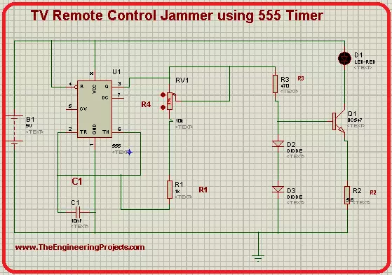
Hey pupils, welcome to The Engineering Projects. We hope you are doing great. In today's simulation in Proteus ISIS, we'll seek the knowledge of an interesting topic. We are going to design a Television remote jammer in Proteus. We all are familiar with the TV Remote controller device and know it works when a light signal emitted by it is sensed by the television. Have a glance at the topics we will see in detail today:

  1. Introduction to 555 Timer TV Remote Control Jammer.
  2. Components of the circuit.
  3. Working principle of 555 Timer Jammer.
  4. Simulation of the Jammer of TV Remote Control using 555 Timer.

Moreover, you will also learn some interesting facts about the topic in DID YOU KNOW sections. let's jump to our first topic.

555 Timer TV Remote Control Jammer

Remote controls do not require any introduction. We all use many types of remote controller devices in our daily lives. The TV Remote controls work on the principle of Infrared light. Yet, what if we do not want to give any access to other users or there is a requirement of blocking the signals from the remote controller device. In this case, jammers are useful because they do not alter any functioning of remote controls and just distract the television to sense the light signals. On this basis, we define the 555 Timer TV Remote Control Jammer as:

  • The 555 Timer TV Remote Jammer is a device used to jam the Infrared Lights emitted by the remote control, by producing a constant pulse of signals and distract the remote controller signals.

Before starting the working of the TV Remote control Jammer, let's have a piece of quick information on how does the TV Remote works. When we press the button of the remote, it sequentially emits the pulses. These pulses are then received by the IR Reciever present in the Television. Each time, every button has its own frequency of pulses so that the IR Reciever can sense which button is pressed. Then the TV act according to our command.

Now, in the case, when we want to cease the television to sense these signals, we just create a pulse, more powerful than TV remote controller, to disturb the pulse from the TV remote controller, so that the TV will not be able to sense pulses from TV Remote. We'll find how does this works in a bit.

DID YOU KNOW?
  • In electronics, the Jammer is any device that is used to prevent the instruments to sense the signals, waves or other mediums to cease their response.

Components used in TV Remote Jammer

In our circuit, we are going to use different components such as diodes, resistors, capacitors, etc. Out of them, 555 Timers and transistors are important to understand.

555 Timer in TV Remote control Jammer

The 555 Timer is an excellent Integrated circuit used in thousands of electronic circuits. It is used to transmit the pulses and control the flow of the circuit. The main reason behind its large number of projects and circuits is its modes. Basically, the 555 Timer can be used in three modes:

  • Astable Mode
  • Bistable Mode
  • Monostable Mode

For our circuit, we'll go for Astable Multivariable mode. This mode is chosen so because the IR waves from the remote control have very specific wave frequencies. In this way, when the waves from TV control Jammer will be Astable, this will be better to distract the TV from the remote's pulses. The 555 Timers is an 8 pin IC. In our circuit, pin 5 and pin 7 of the 555 Timer will remain unconnected. Other pins will be connected according to their respected functions.

Transistor in Remote Control Jammer

It's an NPN Transistor with three terminals called Emitter, Collector, and Base Terminals. In our experiment, the BC547 transistor will be used. The transistor will act as an amplifier in the circuit to make the pulses generated by the 555 Timer more clear, strong, and effective.

Complete List of Components required

  1. 555 Timer IC
  2. Resistor
  3. Diode
  4. Capacitor
  5. POT HG
  6. LED
  7. Battery
  8. BC547
  9. Ground Terminal

Working of TV Remote Control Jammer using 555 Timer

  1. The working of the circuit starts when the 9V Battery starts its work.
  2. This power enters 555 Timer through its two pins. The 555 Timer, in our case, is in Astable mode.
  3. In this way, the 555 timer generates a pulse that is not stable.
  1. To make the pulses more strong and effective, we use the Transistor. The transistor here works as an amplifier and amplifies the pulses coming towards it through its base terminal.
  2. The output of 555 Timer IC then passes through a couple of Diodes that are connected to the base and Emitter terminal of the BC547.
  3. Ultimately, the pulses of the 555 Timer IC pass through the LED and then to the collector Terminal of the Transistor.
  4. The LED shows the speed of the output pulses.
  5. This abrupt pulse is enough to distract the Infrared Reciever of the Television.
  6. So, as a result, we get a strong pulse of 36KHz-38KHz carrier frequency,

TV Remote Jammer circuit using 555 timers in Proteus

The simulation of the circuit is easy if you follow the steps given below carefully. So Let's go ahead.

Procedure to design circuit of TV Remote Jammer

  • Excite you Proteus Software and start a new Project.
  • Hit the "P" button then choose the first 8 components from the window that appeared.
  • Now arrange all the chosen components on the screen by following the image given next.
  • Go to the left side of the screen>Termnals mode>Ground and attach this ground terminal below the circuit.
DID YOU KNOW?
  • The mode of 555 Timer is identified by the components and their manner of connection with 555 Timer.
  • You can change the frequency of the pulses by changing the values of the components.
  • This change can easily be detected by observing the speed of the power entering the LED.
  • To connect them, let's use connecting wires.
  • You can alter the values of some components as:
POT HG: 1K, R1: 1K, R2: 5.6, R3:470, C:110nF,Battery:9V.
  • Go to virtual instrument Mode>Oscilloscope and fix it with the LED's output.
  • Finally, at the present moment, we are going to simulate our circuit.
  • Click on the play button and set the values of voltage and frequency through nobs.
  • The output of the oscilloscope will show that waves are formed frequently.

In the end, we conclude that we can design the circuit of the TV remote control jammer using the 555 Timer in Proteus. We had a short introduction to how does TV Remote works, we saw how can we jam its signal, we found how does the circuit works and at the end, we design a full circuit of a TV remote control jammer with the help of 555 timers in Proteus ISIS. This circuit emits a constant bit of 1.775 meters per second and the frequency ranges from 36KHz to 38KHz.

Traffic Light Circuit using 555 Timer in Proteus

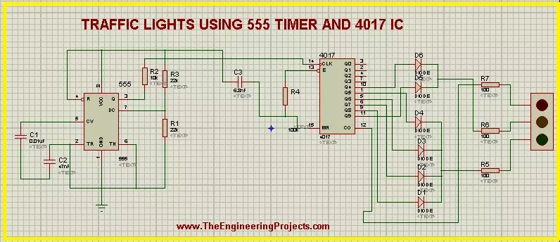
Hey pals! Welcome to the board. We are talking about a fascinating experiment about The Engineering Projects. We all know about the Traffic Lights. But today, we'll see inside the Traffic Lights and find some interesting working of the circuit of Traffic Lights. Before this, just have a look at the topics of discussion:

  1. What is the Traffic Lights circuit with 555 Timer?
  2. What does the 555 timer do in Traffic Lights?
  3. What is the purpose of the 4017 IC Counter in the circuit?
  4. How does the circuit of Traffic Lights work with 555 Timer IC?
  5. How can we perform experiments with the circuit of 555 Timer Traffic Lights in Proteus ISIS?

In addition, we'll see some important points about the topic in DID YOU KNOW sections.

Traffic Lights circuit with 555 Timer

Whenever we rush toward any road that has a heavy flow of vehicles, we always follow some traffic rules. One of the most fundamental traffic rules is to follow the traffic lights. These traffic lights direct the vehicles to start or stop moving at the road according to our turn. These turns are decided by the Traffic Lights. The traffic Lights show the different colored lights and these lights turn on and off in a sequence. We know all these things, but we are revising these to get the logic behind the scene. we define the Traffic Lights technically as:

"The traffic lights are the combination of three LEDs colored as red, amber and green that are connected in a specialized circuit that gives the output from the LEDs in a specific format and this format is used to control the flow of traffic."

These LEDs are enclosed in a metallic body. Traffic Light signals are so useful that 99% of the countries use them. This makes the circuit one of the most fundamental and common circuits to understand.

There are many devices through which the Traffic Lights may be controlled. Out of which, two are common:

  1. Traffic Lights with the D Flip Flop.
  2. Traffic Lights with 555 Timer

We have discussed the 1st method in our previous tutorial, Let's have a look at the next one.

555 Timer IC Performance in Traffic Lights

before starting the simulation, let's have a look at its components briefly. The circuit of Traffic Lights uses a very common yet powerful device i.e, 555 Timer IC. The 555 Timer is so useful that it is said that annually, a billion of 555 Timers are produced and it is considered as the most popular IC of the year 2017. We introduce the 555 Timer as:

"The 555 Timer is a common 8 pins Integrated Circuit used in a variety of oscillation generators and Timers to generate a pulse of the signals that control the output sequentially."

In our experiment, we'll apply the Mono-stable Multi-vibrator mode of the 555 timer. The output of 555 Timer in this mode is in the form of a single pulse of current that has a specific length. This pulse is sometimes called the one-shot pulse.

4017 IC in the 555 Timer Traffic Lights

The 4017 is the special IC that is usually coupled with the 555 Timer. It works on the pulse generated by the 555 Timer and the definition for the 4017 IC is given as:

  • "The 4017 is 16 pins counter and decoder of 555 Timer IC that generates a decade counter output from its output pins and the outputs advances from one to another with the positive edge of the clock pulse."

Once the clock pulse of 4017 IC in the traffic Lights goes from low to high, the IC started its cycle again and we get a sequential Logic output. The pins 3 to 12 of the 4017 IC Counter are said to be the output pins of the 4017 and we'll connect the traffic lights with them.

Working of Traffic Lights using 555 Timer IC

  1. The Working of the circuit starts with the power connected to the Vcc terminal of 555 Timer IC.
  2. the power in the 555 Timer in Mono-stable Multi-vibrator mode produces a uniform pulse of current that is stabilized with the help of capacitors used with the 555 Timer IC.
  3. The current is then fed into the clock terminal of the 4017 decade counter IC that decodes these pulses of 555 Timer IC and produces the stream of output at its output terminals.
  4. The terminals of the 4017 IC are connected to the diodes in a specific manner. These diodes conduct the electricity on only one side and so that a specialized sequence of the current is found at the outputs of these diodes.
  5. There are two sets of the diode connections. Four diodes are connected in a set and two in another. The output of 1st set is fed to Green Light of the Traffic Lights. The Amber and Red lights of the circuit are connected with the second set.
  6. The output of these two sets is connected with the resistor and then finally this current passes to the traffic Lights signal.
  7. In the end, we get a specialized, clear and automatic output from the traffic lights.

Simulation of the circuit of 555 Timer Traffic Lights in Proteus ISIS

At the moment, we are going to design the circuit of the experiments. So let's start.

Devices required for 555 Timer Traffic Lights

  1. 555 Timer IC
  2. 4017 IC
  3. Capacitors - 3
  4. Resistors - 7
  5. Diodes - 6
  6. Traffic lights
  • Fire up your Proteus Software.
  • Choose the material from pick Library through "P" button.
Let's divide the circuit design into three parts:
  1. 555 Timer connections
  2. 4017 IC Counter connections
  3. Connection of 555 Timer and 4017 IC

555 Timer Connections

  • Choose the 555 Timer from the component's area and arrange it on the left side working area.
  • Select the resistor then  arrange three resistors with pin 3, 6 and 7.
  • Take capacitor and set two capacitors with pin 2 and 5 of 555 Timer.
  • Go to terminal mode and set a Ground terminal at the Ground pin of the 555 Timer.
  • Connect all the components of 555 Timer IC as:

Connections of 4017 IC

  • Go to components, choose 4017 IC.
  • Select diode and arrange the 7 diodes with the output pins on the right side of 4017 IC.
  • Take care with the direction of the diodes.
  • Set a resistor between the pins 13 and 16 of 4017 IC.
  • Arrange three resistors  just after the diodes.
  • Now set a Traffic Light signal on the right side of the resistors.

DID YOU KNOW?????????????????????????????

It is said by AAA, the average American spends 58.6 hours every year waiting at the red light of traffic signal.
  • The circuit now looks like the image given next:

Connection of ICs

  • Now, at the moment, we'll connect the ICs to finally set our circuit.
  • Set a capacitor between both these ICs.
  • Alter the names of the components by given them numbering so that Proteus may distinguish between different Resistors, Capacitors, diodes and ICs.
  • Change the values of each component according to the table given next:
Component Values
C1 0.01uF
C2 47uF
C3 6.8nF
R1 23k ohm
R2 10k ohm
R3 22K ohm
R4 100k ohm
R5 100 ohm
R6 100 ohm
  • Observe deeply the image given below and connect all the components with the help of connecting wires.
  • Our circuit is now good to go, Let's tap the play button and simulate the circuit.
The circuit shows the required output well. If you found any error, look at the steps given above again.

DID YOU KNOW????????????????

The working speed of the Traffic Lights can be varied by changing the values of capacitors connected with  pin 5 and 2 of the 555 Timer IC.
So, today we saw a fantastic circuit in which we learned that what are the Traffic lights signal using 555 timer, how does the ICs of 555 timer and 4017 IC Counter work with each other to show the output of the Traffic Lights and we designed the circuit of 555 Timer Traffic Lights in Proteus ISIS. If you have any questions, you can contact us through the comment sections.

Simplest LM386 Audio Amplifier in Proteus

Hey Learners, welcome to another exciting tutorial about electronics. We are talking about an audio amplifier using LM386. This is a very simple IC that we are going to used for the amplification of the audio signals. We shall go through the core postulation about the topic and then work on the practical implementation of the experiment. Just have a look at the topics of discussion:

  1. Introduction to LM386 Audio Amplifier.
  2. Components of LM386 Audio amplifier.
  3. LM3386 Audio Amplifier Working.
  4. Simulation of the LM386 Audio Amplifier Circuit in Proteus.
In addition, you will find interesting information in the DID YOU KNOW sections.

Introduction to LM386 Audio Amplifier

Audio signals play important role in many devices. These signals are used to regulate the life of the community in many ways. These signals, when required, are amplified by some means to use them more effectively and efficiently. Many devices can do this task. Yet, at the present time, we are going to discuss LM386 Audio Amplifier. Let's have its definition:

  • "The LM386 audio frequency Amplifiers are the types of low power audio amplifiers used commonly in small amplifier systems and can be run on even a 9V battery."

The input signals once pass through the LM386, are amplified and the user senses a loud sound as compare to the input signal. This type of amplification is really important in the circuits where a signal is required to show the completion of the task, requirement of the involvement of the user or an error in the circuits.

Components of the circuit of LM386 Audio Amplifier

In this article, we're using the very simple circuit of LM386 Audio Amplifier to show the easy but understanding hypothesis of the topic. This circuit consists of capacitors, audio signals, LM386 IC, power source and speaker, out of which, we have to discuss the LM386 IC, Audio signals and speaker.

LM386 IC

The LM386 is a versatile chip that can easily be used in many kinds of circuits. The IC  runs no low voltage, therefore it is a very common yet power operational amplifier that is used even in DIY guitar pre-amplifiers. If we look at the basic definition of LM386 then we find:
"The LM386 is an 8-pin Dual inline integrated circuit that can work on very low voltage and when connected with some simple components can be used as an operational amplifier in a large number of amplifying circuits."
The power intake and efficiency depends totally upon the models of the LM386. Basically, there are three models of aLM386 IC as mentioned below:
Number of Pin Name of pin
1 Gain
2 Negative input
3 Positive Input
4 Ground
5 Gain
6 Bypass
7 Input power
8 Output of IC
Being an op-amp, the LM386 has a very basic task. The IC gets the power from its input terminals and using its circuitry, it amplifies the power output signal on the rate of tens, hundreds, thousands and so on. The total output purely depends upon the input and the model of LM386.

Speaker

The speakers are the devices that takes the audio signals and convert them into voice. This conversion is done by the special mechanism of speaker. In this experiment, the output will me hear with the help of this speaker.

Variable Resistor

As the name describes, the variable resistor is the special device that is capable of changing the value of resistance according to the requirement of the user. The + and - terminal of variable resistor are used to increase and decrease the resistance respectively. In this way, the input audio signals can be controlled.

Working of LM386 Audio Amplifier

  1. The working of the LM386 Audio Amplifier starts with the audio signal generation of audio generator.
  2. These signals passes through the capacitor that regulates these signals and then pass them to the LM386.
  3. The IC inputs these signals, the pin 6 of the LM386 is connected with the DC Source hence it powers it up. The IC now amplify the audio signals.
  4. From pin 5 of the IC, the amplified audio signals are generated. Meanwhile, the resistor and capacitor regulates the signal so that the user may sense these signals in the right sequence of waves.
  5. Finally, the speaker takes these signals as input and convert it in the form of sound so that the user can hear it easily.

Procedure to simulate the LM386 in Proteus ISIS

By availing all the information given above, let's simulate the circuit in Proteus ISIS. Just apply the instructions given below:

Material Required

  1. LM386 IC
  2. Resistor
  3. Capacitor
  4. POT HG
  5. Speaker
  6. Ground Terminal
  7. Audio device
  • Start your Proteus ISIS.
  • create a new Project.
  • Click on P button.
  • Choose 1st five components mentioned in the list given above.
  • Arrange all the components on the working area by following the image given next:
  • Go to Terminal Mode from the left side of your screen and choose ground. Now, set it just below the circuit.
  • Go to Generator mode>choose audio and set it just on left side of arrangement.
  • Double click the audio probe>brows>upload this file.
  • [audio wav="https://www.theengineeringprojects.com/wp-content/uploads/2021/06/file_example_WAV_1MG.wav"][/audio]
  • Change the values of the components as described in the following table :
Component Value
C1 1nF
C2 100F
C3 1uF
C4 47nF
C5 47 nF
C6 220uF
R1 10 ohm
R2 10 ohm
DC Power Supply 9V
 
  • Once all the values are changes, just go to virtual Instrument mode and select the oscilloscope above the components.
  • At this time, join the components with the help of connecting wires.
  •  Hit the Play button with your mouse and simulate the circuit.
  • Change the values of the voltages of terminals and current through the nobs to get the visible wavelengths.
one can see clearly that the output signal(blue waves) are more amplifier and strong than the input signals (Yellow waves).

Conclusion of experiment

The LM386 is the IC that can be used to amplify the audio signals. The input frequency and thus the volume of the sound amplifies and we can hear the loud sound. One can change the intensity of sound by using the active variable resistor.

RC Electronic Circuits Simulation in Proteus ISIS

Hello friends! Welcome to the Engineering components. Today, We are talking about the very common topic of electronic devices. In this tutorial, we'll pick very common components and learn about their role in circuits. If you are a beginner in the world of electronics, you must read this article till the end because we'll learn all the things from scratch till the completion of the circuit. In this article, you will learn:

  1. Introduction to electronic circuits
  2. Categories of electronic circuits.
  3. Introduction to Resistor and Capacitor.
  4. What are RC Circuits?
  5. Simulation of R Circuits in Proteus ISIS.
Let's look at the description.

Introduction to Electronic Circuits

We come across many circuits in our daily lives, some of them are electrical circuits and some are electronic circuits. There are many differences between them but the main difference is, that electrical circuits do not have decision-making capacity whilst electronic circuits do have this ability. In electronic circuits, we power up the components with the mean power source and get the output. Hence we may define the electronic circuits as:

  • "The electronic circuits are the types of circuits in which the individual electronic components are used that are connected to the power source with the help of wires so that the current can pass through the components."

The electronic circuits are also called discrete circuits because they are somehow, opposite to the integrated circuits. Most of the circuits use a combination of electrical and electronic circuits.

Categories of Electronic components

As we know, electronic components are used in many ways. For convenience, we divide the electronic components into categories. These are categories into two main sections:

  1. Active Components.
  2. Passive components.

The main focus of this article is passive components. The passive components include Capacitor, Resistor and Inductor. These are symbolized as C, R and L respectively. We'll learn about the first two of them today.

Introduction to Resistor and capacitor In electronic circuits

The Resistor and capacitor may be said to be the backbone of thousands of electronic circuits. To design a circuit, one should have a clear concept of these components. So, Let's have their introductions:

Resistor in Electronic Circuits

As the name implies, the resistor shows the resistance for the current in the circuit. It has a tube-like shape that has a molded figure and has a wire at the start and end. One may define the resistor as:

  • The resistor is a passive, bi-terminal electrical component that is used in the circuit to have the electrical resistance in the current. When we use it in electronic circuits, it reduces the sudden current flow in the circuits, biases the active elements, divides the voltages in the circuit and performs such other tasks.
Current is the flow of electrons, this flow should be resisted by some mean, so that the components used in the circuit will be safe from damage. To control this opposition, one must have a clear idea about the resistance. The resistance is the measure of the property of the resistor to oppose the current in a circuit. The resistance of the resistor is symbolized by the strip of different colors. Each color has a meaning of different value.

Capacitor in Electronic Circuits

The capacitor works like a battery. The body of the capacitor is so simple and easy to understand, yet plays an important role in many types of circuits. The introduction of Capacitor is given next:
  • The capacitor is an electrical component consists of two metallic plates and two wires connected with two plates that store energy passes through it in the form of an electrostatic field in between its two metallic plates. Its body is packed in an envelope.
As you can see in the picture, capacitors are manufactured in the form of a tube-like shape with two wires that are used to connect within the circuit. The capacitors are made in a variety of ranges according to their role in the circuit.

RC Electronic Circuits

As we know the Resistor is denoted as R and the capacitor is denoted by C. The RC circuits are the simple and easy circuits to understand.  We introduce the RC Electronic circuits as:
"The RC Circuits are the Resistor-Capacitor circuit in that consist of only resistor and capacitor as passive components of capacitor and these are connected with the current or voltage source according to the type of circuit."
One should keep in mind that we are talking about the category of passive components right now. Otherwise, some other components such as the power generating component are also used in the circuit. The are two categories of RC Circuits mentioned next:
  1. RC Series circuit.
  2. RC Parallel circuit.
RC Series circuits are the ones in which the resistor and capacitors are connected in series whereas, when we talk about the RC Parallel circuit, the R and C are connected in parallel to each other. RC circuits are also called the filter circuit or network circuit because many RC circuits are used to filter the unwanted frequencies of signals from the circuit and keep only the required ones. The RC Circuits are further classified on the basis of the number of components used in the circuit. The circuit is called the first-ordered RC Circuit if it contains only one resistor and one capacitor. Similarly, if it has two resistors and capacitors then the circuit is called the second ordered RC Circuit. To have a clear idea about the circuit, design it on the Proteus.

RC Electronic circuits in Proteus ISIS

To experiment, just follow the steps given next:

Required Components

  1. Resistor
  2. Capacitor
  3. Battery
  4. Connecting wires

Procedure

  • Start your Proteus software.
  • Click on the "P" button and choose the required components one by one.
  • Arrange these components in the working area.
  • Connect the components with connecting wires.
  • Play the circuit with the play button present on the lower-left corner of the screen.

This image shows two types of circuits. The upper circuit is the RC Series circuit and the lower circuit is the RC Parallel circuit. Hence today, we learned about the introduction of Electronic circuits, we saw what are RC circuits, their components and their types depending upon different parameters. We also simulated the circuits in Proteus.

Pure Sine Wave Inverter using 555 Timer in Proteus.

Hi Mentees! Welcome to another electronic tutorial about the 555 Timers. We are working on Proteus and in the present experiment, we'll design the circuit of Pure Sine Wave Inverter. Inverters are the opposite devices to rectifiers. We'll show you the meaning of this sentence in action Yet, before experimentation, we have to learn some predominant concepts about the experiment. So, We'll go through the following topics:

  1. Introduction to Pure Sine Wave Inverter.
  2. Components used in the circuit of Pure Sine Wave Inverter.
  3. Working of the circuit of sine wave inverter.
  4. Circuit simulation of pure sine wave inverter in Proteus.

Introduction to Pure Sine Wave Inverter

In electronics, we examine the output of devices in the form of waves. Basically, there are four types of waves including sine wave, sawtooth wave, square wave and triangular wave. The title of the circuit we are discussing today consist of two main concepts:

  1. Sine Wave
  2. Inverter

Let's recall them one after the other.

  • Sine Wave: The sine wave is a mathematical curve that is a smooth, s-shaped, periodic, continuous wave and is described as the graph of sin function indicated by Y=sin x.

The sine waves are used in Mathematics, physics, engineering, signal processing and other related waves. In Electronics, the sine wave indicates the AC.

  • Inverter: Inverters are the electronic devices that are used to convert the DC into AC. We can say, Inverters are the opposite circuits of rectifiers. The purpose of this inverter is the same.

Hence, when we combine these concepts, we get the following definition of Pure Sine Wave Inverter:

  • "The Pure Sine Wave Inverter is a circuit that takes the input in the form of DC and gives output as AC. It is used to run any type of instruments designed to run on smooth sine wave output."

We can make the circuit with the many methods, out of which two are:

  1. Pure Sine Wave inverter through MOSFET.
  2. Pure Sine Wave Inverter through 555 Timers IC.

The focus of this article is the 2nd type. So let's look at its circuit.

Circuit of Pure Sine Wave Inverter using 555 Timer

If you understand the working of its components, the circuit of the sine wave inverter is quite simple. It consists of some simple electronic components that every engineer uses many times. But out of them, 555 Timer and Transformer should be discussed here.

555 Timer

The 555 Timer is a great integrated circuit. It is used in thousands of circuits that have the requirement of pulses with uniform length. It is an 8 pin integrated circuit that may be used in three modes. In this tutorial, we'll use the 555 Timer in Astable Mode.

Transformer

A transformer is a passive electronic device that is used to transfer electrical energy from one source to another by the mean of electromagnetic induction. The main purpose of the transformer is to change the level of the input current (high or low) to the output current. The circuit of Pure Sine Wave Inverter is designed so, we provide the 12V DC as input and get the 240V AC as output. In addition to these, we will use Inductor, diode, capacitor, resistor and power source in our circuit.

Working of Pure Sine Wave Inverter using 555 Timers

  • The working of the Pure Sine Wave Inverter starts when the 12 volts DC is applied to the components.
  • These 12 volts enter the 555 Timer through pin 3 of the 555 timer that is in the Astable Mode. Due to this Mode, the 555 timer produces a single uniform pulse that is fed into the inductor.
  • Every time, when a new pulse enters the inductor, it stores the energy in the form of an electromagnet. In the time t, when this energy is fully discharged through the inductor, its signs of induction change. After that, a new pulse enters the inductor and this process goes on. This energy passes through the resistor and finally fed into the transformer.
  • In our case, the transformer is stepped high and it gives us the output of 240V AC. One can check this using AC Voltmeter.
  • The diode connected to pin 7 of 555 Timer passes the current in only one direction (because it is a diode) and sends this pulse to the transformer by the mean of a capacitor for a steady pulse.

Simulation of Pure Sine Wave Inverter in Proteus

Using all the concepts discussed above, let's get started with the simulation of the circuit by following the simple steps.

Required Devices

  1. 555 Timer
  2. Vsource (DC power source)
  3. Diode
  4. Capacitor
  5. Inductor
  6. Transformer
  7. Resistor
  8. Connecting Wires
  9. Ground Terminal

Circuit Simulation of Pure Sine Wave Inverter

  • Excite your Proteus simulator.
  • Start a new Project
  • Tap to the "P" button of the screen and choose 1st seven devices one after the other from the list of required devices.
  • Arrange all the devices on the screen by following the image given below:
  • Left click on the screen>Go to Place> Terminal>Ground and set it just below the circuit.
  • Change the Values of the devices according to the table given next:
    Components Values
    R1 1KR
    R2 1KR
    R3 0.02KR
    C1 1nF
    C2 100nF
    C3 100uF
    Inductor 1mH
    Transformer Primary= 1H, Secondary= 2000H
  • Go to Instruments>Oscilloscope and set it at the output side.
  • Connect terminal A with
  • Now connect all the components carefully with the connecting wires.
  • Click on the Play button just at the lower-left corner of the screen and start the simulation.
  • You will find the Sine Wave Inversion on the output screen of the Oscilloscope.
Truss, in the present article, we saw the introduction of Pure Sine Wave Inverter, Look at its devices and components, saw the working of the whole circuit and learned to design the circuit in the Proteus practically. We hope you learned well.

Buck Converter using MOSFET Gate Driver in Proteus

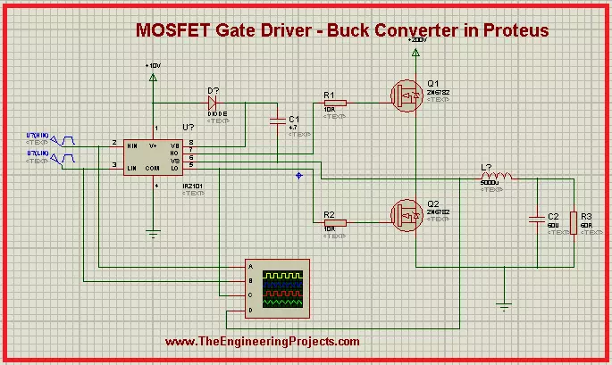
Hey Geeks! Welcome to The Engineering Projects. We hope you are doing great. MOSFET is a predominant component widely used in electronics due to its performance. We are working on the Projects of MOSFET and today's experiment is really interesting. We are working on the MOSFET Gate Driver and we will work on the following concepts:
  1. Introduction to MOSFET Gate Driver.
  2. Circuit of MOSFET Gate Driver.
  3. Working of MOSFET Gate Driver.
  4. Simulation of MOSFET Gate Driver in Proteus.
  5. Applications of MOSFET Gate Driver.
You will find important information about the topic in DID YOU KNOW sections.

Introduction to MOSFET Gate Driver

We all know MOSFET is a type of transistor and is used in a wide range of circuits. It has many interesting features and the characteristics of MOSFET are at the fingertips of electrical and electronic engineers. The circuit of the MOSFET Gate Driver may be new for many students so let's have a look at its definition:
"The MOSFET Gate Driver is a type of DC to DC power amplifier that in the form of on-chip as well as discrete module in which we use MOSFET as the gate driver IC, the low power is taken as input from MOSFET and high power is obtained its gate terminal and vice versa according to need." 

DID YOU KNOW?

The name of the MOSFET Gate Driver is due to its characteristic to have the high current drive gate input of a Transistor. We use the MOSFET because it is a gate driver IC.
MOSFET is used in this circuit because it is commonly used in switching devices where the frequency ranges from hundred of KHz to thousands of KHz. It is mostly used in appliances where we need DC to DC amplification. It is used in computers to low their temperature during their performance. The MOSFET Gate driver is used to change the value of DC according to the circuit of the appliances. There are three types of drivers:
  1. High side drivers.
  2. Low side Driver.
  3. Isolated Drivers.
 

Circuit of MOSFET Gate driver

When we look at the circuit of the MOSFET Gate drive, we found there are some basic as well as some special components in the circuit. In addition to MOSFET, the circuit consists of resistor, capacitor, inductor and IR2101. Let's look at their functions:

MOSFET

  • Metal Oxide Semiconductor Field Effect Transistors have a thin layer of silicon oxide between Gate and channel. It four terminals:  Gate, Drain, Source.

IR2101

It is IC that works very great with MOSFET. We use it in the MOSFET Gate driver to insert the voltage in the Gate terminal of the MOSFET in the form of pulses. We define the IR2101 as:
"It is  seven pins, high power, high voltage, MOSFET and IGBT driver that has independent high and low channel references."
The detail of the pins is given as:
  1. Vcc: This Pin is for Low side and logic fixed supply voltage.
  2. Vs: It is for High side floating supply offset voltage.
  3. Hin: High side gate driver output is taken by this pin.
  4. HO: We get High side gate drive output through this pin.
  5. Lin: Low side gate driver output is taken by this pin.
  6. LO: Low side gate drive output is obtained through it.
  7. COM: we get Low side return from this pin.
Other components are very common to discuss.

Working of MOSFET Gate Driver

The working of the MOSFET Gate Driver start when the power is generated from power terminals.
  1.  The IR2101 starts with the power terminal, the input pulse generators convert this power into the special length as set by the user.
  2. These pulses Enter at the gate terminals of MOSFETs.
  3. Both of these MOSFETs do not turn on at the same time. They work in a loop so that if the high side MOSFET is turned on then the other is off and vice versa.
  4. The MOSFET M1 on the upper side of the circuit is considered at the High side of the driver and the MOSFET M2, on the lower side of the circuit is at the Low side driver.
  5. After some time, when the voltage becomes greater than the threshold voltage of MOSFETs, they start working.
  6. The terminals of  MOSFETs are connected with the capacitor.
  7. The aim of this circuit is to charge the capacitors. Hence when the MOSFET starts working, the charging of the capacitor takes place.
  8. The pulses reach both the MOSFET at a very specific time due to IR2101.
  9. Once the capacitor C2 is fully charged, it starts the discharging power and this discharging power from the inductor as well and at last, it goes to the ground terminal.
  10. In this case, the polarity of the inductor changes and in this way, the energy stored in the capacitor is discharged.
  11. Hence at the end, when we check on the oscilloscope, we get the changed output pulse from the input.

Simulation of MOSFET Gate Driver in Proteus ISIS

Material Required for MOSFET Gate Driver

  1. MOSFET
  2. IR2101
  3. Resistor
  4. Capacitor
  5. Inductor
  6. Ground Terminal
  7. Power Terminal
  8. Pulse Generator
Using all the concepts given above, we'll simulate the circuit in Proteus for a crystal clear concept. Just follow the steps given next:
  • Start your Proteus Software.
  • Make a new Project.
  • Click at "P" button to choose the first five components for the experiment one after the other.
  • Arrange all the components in the working area according to the arrangement given next:
  • Go to Terminal Mode> Ground and add ground terminal with the required components of the circuit.
  • Repeat the above step with the power Terminal.

DID YOU KNOW?

The efficiency of MOSFET Gate driver is more than 90% in many cases.
  • Go to Instrument Mode and take the Oscilloscope from there. Now, arrange it just below the circuit.
  • Connect all the components with the help of connecting wires by carefully following the image given next:
  • Double-tap the components one by one and change the default values according to the table given next:
    Components Values
    R1 10R
    R2 10R
    R3 60R
    L1 500u
    C1 4.7u
    C2 60u
    Pulse 1 Pulse (High) voltage =5v, frequency 1k, Pulse Width 50%
    Pulse 2 Pulse (High) voltage =5v, frequency 1k, Pulse Width 50%
  • Tap the play button at the lower-left corner of the screen to simulate the graph.
  • Set the values of voltage and current through the nob to see a clear output.

Applications of MOSFET Gate Driver

  1. MOSFET Gate driver is used in DC to DC converter.
  2. It is used in the conversion of high voltage to low voltage.
  3. It is mainly used to reduce heat in many circuits.
  4. Due to its functions, it is useful in extending battery life.
So, in the present article, we saw what is MOSFET Gate driver. What important components are used in it, how does its circuit works and how can we simulate its circuit in Proteus. Moreover, we also read some of its applications. We hope you learned well from this article.
Syed Zain Nasir

I am Syed Zain Nasir, the founder of <a href=https://www.TheEngineeringProjects.com/>The Engineering Projects</a> (TEP). I am a programmer since 2009 before that I just search things, make small projects and now I am sharing my knowledge through this platform.I also work as a freelancer and did many projects related to programming and electrical circuitry. <a href=https://plus.google.com/+SyedZainNasir/>My Google Profile+</a>

Share
Published by
Syed Zain Nasir