Serial Communication with 8051 Microcontroller in Proteus

Hello friends, hope you are having fun. In today's post, we will have a look at Serial Communication with 8051 Microcontroller in Proteus ISIS. In the previous post, we have seen a detailed post on LED Blinking Project using 8051 Microcontroller in Proteus ISIS, which was quite a simple tutorial. And I hope if you are new to 8051 Microcontroller then from that post you must have got some idea about C Programming of 8051 Microcontroller.

Now, today we are gonna go a little further and will have a look at Serial Communication with 8051 Microcontroller and we will also design the simulation of this project in Proteus ISIS software. 8051 Microcontroller also supports Serial port similar to Arduino and PIC Microcontroller. And the communication protocol is exactly the same as its a Serial Port. But obviously the syntax is bit different as we are not working in Arduino software or MPLAB. So let's get started with it.

Serial Communication with 8051 Microcontroller in Proteus

  • Let's first have a little recall of Serial communication. In serial communication we have two pins which are named as TX and RX.
  • TX pin is used for transmitting data while the RX pin is used for receiving data.
  • So, our microcontroller has these two pins as it supports Serial Communication and these pins are located at Pin no 10 and 11 in AT89C52 Microcontroller, which I am gonna use today.
  • First of all, we will design a Simulation of this project in which there will be 8 LEDs attached to Port 1 and by sending characters through Serial port, we will either turn these LEDs ON or OFF.
  • After designing the Simulation, we will then design the programming code for 8051 Microcontroller and will test our result.
  • So, let's get started with Proteus Simulation of Serial Communication with 8051 Microcontroller.
Proteus Simulation
  • Open your Proteus software and get these components from your Proteus Component Library:
  • Now, design a circuit for Serial Communication with 8051 Microcontroller in Proteus software as shown in below figure:
  • Now in the above figure, I have used crystal Oscillator of 16MHz as I did in the previous post LED Blinking Project using 8051 Microcontroller and again the reset is pull Down.
  • Next I have attached Virtual Terminal with TX and RX of 8051 Microcontroller, if you don't know about Virtual Terminal much then I suggest to read How to use Virtual Terminal in Proteus ISIS.
  • Finally, I have attached the 8 LEDs on Port 1 so that we could check whether we are getting correct data or not.
  • Now let's design the programming code.
Programming Code
  • Now open your Keil micro vision 4 software and paste the below code into it.
#include <reg52.h>

#define Baud_rate 0xFD  // BAUD RATE 9600                     

void SerialInitialize(void);
void SendByteSerially(unsigned char);    
void cct_init(void);

sbit Appliance1 = P1^0;
sbit Appliance2 = P1^1;
sbit Appliance3 = P1^2;
sbit Appliance4 = P1^3;
sbit Appliance5 = P1^4;
sbit Appliance6 = P1^5;
sbit Appliance7 = P1^6;
sbit Appliance8 = P1^7;


void main()
{
    cct_init();
    SerialInitialize();    

    EA = 1;
    ES = 1;

    while(1) {;}
}


void cct_init(void)   //initialize cct
{
    P0 = 0x00; //not used
    P1 = 0x00; //Used for Appliances
    P2 = 0x00; //not used
    P3 = 0x03; //used for serial

}

void SerialInitialize(void)                   // INITIALIZE SERIAL PORT
{
    TMOD = 0x20;                           // Timer 1 IN MODE 2 -AUTO RELOAD TO GENERATE BAUD RATE
    SCON = 0x50;                           // SERIAL MODE 1, 8-DATA BIT 1-START BIT, 1-STOP BIT, REN ENABLED
    TH1 = Baud_rate;                       // LOAD BAUDRATE TO TIMER REGISTER
    TR1 = 1;                               // START TIMER
}

void SendByteSerially(unsigned char serialdata)
{
    SBUF = serialdata;                        // LOAD DATA TO SERIAL BUFFER REGISTER
    while(TI == 0);                            // WAIT UNTIL TRANSMISSION TO COMPLETE
    TI = 0;                                    // CLEAR TRANSMISSION INTERRUPT FLAG
}

void serial_ISR (void) interrupt 4
{
    //receive character
    char chr;
    if(RI==1)
    {
        chr = SBUF;
        RI = 0;
    }

    P0 = ~P0;    //Show the data has been updated

    switch(chr)
    {
     case '1':  Appliance1 = 1; SendByteSerially('k');  break;
     case '2':  Appliance2 = 1; SendByteSerially('k');  break;
     case '3':  Appliance3 = 1; SendByteSerially('k');  break;
     case '4':  Appliance4 = 1; SendByteSerially('k');  break;
     case '5':  Appliance5 = 1; SendByteSerially('k');  break;
     case '6':  Appliance6 = 1; SendByteSerially('k');  break;
     case '7':  Appliance7 = 1; SendByteSerially('k');  break;
     case '8':  Appliance8 = 1; SendByteSerially('k');  break;


     case 'a':  Appliance1 = 0; SendByteSerially('k');  break;
     case 'b':  Appliance2 = 0; SendByteSerially('k');  break;
     case 'c':  Appliance3 = 0; SendByteSerially('k');  break;
     case 'd':  Appliance4 = 0; SendByteSerially('k');  break;
     case 'e':  Appliance5 = 0; SendByteSerially('k');  break;
     case 'f':  Appliance6 = 0; SendByteSerially('k');  break;
     case 'g':  Appliance7 = 0; SendByteSerially('k');  break;
     case 'h':  Appliance8 = 0; SendByteSerially('k');  break;


     default: ;    break;     //do nothing
    }

    RI = 0;
}
  • You can see in the above code that baud rate we have used is 9600and we have used a switch case method for turning ON or OFF Leds.
  • So, now what it will do is when you send 1 on Serial Monitor, it will turn ON the first LED and when you send "a" on Serial Terminal then it will turn OFF the first LED. The same will go on for 8 LEDs.
  • Character 1,2,3,4,5,6,7,8 will turn ON the LEDs from 1 to 8 respectively.
  • While the character a,b,c,d,e,f,g,h will turn OFF the LEDs from 1 to 8 respectively.
  • For each command it will reply us back a single character which is "k". So in this way we are doing the two way communication i.e. sending as well as receiving the serial data.
  • So, now after adding the code, get your hex file and then upload it to your Proteus Simulation and click the RUN button on your Proteus software.
  • When you start your Proteus Simulation, all the LEDs will be OFF and the virtual terminal will be open as shown in below figure:
  • So, now click in the Virtual Terminal and press 1 and the first LED will get ON and you will get k in response as shown in below figure:
  • You can see in the above figure, I have pressed 1 and the first LED goes ON as well as we get a response "k" in the virtual Terminal.
  • So, that's how we can turn ON or OFF LEDs so in the below figure, I have turned ON all the 8 LEDs.
  • Now you can see in the above figure,all leds are on and the virtual terminal is showing k for 8 times as I have given 8 instructions.
  • You can download the Proteus Simulation along with hex file and the programming code by clicking the below button.

Download Proteus Simulation and Code

So, that's how we can do Serial communication with 8051 Microcontroller. I don't think its much difficult but still if you have problems then ask in comments and I will resolve them. That's all for today and will meet in the next tutorial soon.

LED Blinking Project Using 8051 Microcontroller

Hello friends, hope you all are fine and having fun with your lives. In today's tutorial, we will see LED Blinking Project Using 8051 Microcontroller. I haven't yet posted any project or tutorial on 8051 Microcontroller. I have posted quite a lot of tutorials on Arduino and PIC Microcontroller, so today I thought of posting tutorials on 8051 Microcontroller. Its my first tutorial on it and I am gonna post quite a lot of tutorials on 8051 Microcontroller in coming week. So, as its our first tutorial on 8051 Microcontroller that's why its quite a simple one and as we did in Arduino we will first of all have a look at LED Blinking Project Using 8051 Microcontroller. In this project, we will design a basic circuit for 8051 Microcontroller which involves crystal oscillator etc. The basic circuit of 8051 Microcontroller is quite the same as we did for PIC Microcontroller. After that, we will attach a small LED on any of its I/O pins and then will make it blink. I have also given the Proteus Simulation along with Programming code designed in keil uvision 4 for download at the end of this post. So, let's get started with it. :)

LED Blinking Project Using 8051 Microcontroller in Proteus ISIS

  • I am gonna first design the simulation of LED Blinking Project using 8051 Microcontroller in Proteus ISIS, as you all know Proteus is my favorite simulation software.
  • After designing the simulation, we will design the programming code for 8051 Microcontroller.
  • In order to design the code we are gonna use Keil micro vision compiler and the version I have rite now is 4. So its keil micro vision 4 compiler for 8051 Microcontrollers.
  • So let's first design the Proteus Simulation for LED Blinking PRoject Using 8051 Microcontroller.
Proteus Simulation for LED Blinking Project
  • So, get these components from Proteus components library and place it in your workspace, these components are shown in below figure:
  • So, now I hope you have got all these components, now design a circuit in your Proteus software as shown in below figure:
  • Now you can see in the above image, I have used crystal oscillator of 16MHz which is used to provide frequency to 8051 Microcontroller.
  • After that we have placed a 10k resistance in path of our Reset pin.
  • LED is connected to first pin of Port 1 which is P1.0.
  • So, now let's design the programming code for 8051 Microcontroller as we are done with the Proteus Simulation.
Keil Programming Code for LED Blinking Project
  • Now as I have mentioned earlier, the compiler I have used for designing the programming code for LED Blinking Project is Keil micro vision 4.
  • So I hope you have this installed on your computer and if not then must install it as otherwise you wont be able to compile this code, but I have also placed the hex file so that you can run the simulation easily.
  • You can download them easily by clicking the Download buttons present at the end of this post.
  • So now create a new project in your keil compiler and paste the below code in your c file.
#include<reg51.h>

sbit LED = P1^0;          

void cct_init(void);
void delay(int a);


int main(void)
{
   cct_init();             
 
   while(1)
   {
       LED = 0;             
       delay(30000);      
       LED = 1;            
       delay(30000);       
   }
}

void cct_init(void)
{  
    P1 = 0x00;    
}

void delay(int a)
{
   int i;
   for(i=0;i<a;i++); 
}
  • Now let me explain this code a bit, first of all, I declare the pin1.0 as LED so that its easy to use it in our code in future.
  • After that I declared two functions. One of them is the delay function which is just adding the delay, while the second function is for initialization of Port 1 as output port.
  • While in the Main function, we have used the LED blinking code in which LED is ON and then OFF continuously and so that make it blink.
  • Now after adding the code in your Keil software, compile it and get the hex file.
  • Upload this hex file into your 8051 Microcontroller which I have used is AT89C52 and hit the RUN button.
  • If everything's goes fine then you will get results as shown in below figure:
  • Now click the below button to get the simulation and the programming code and let me know did it work for you. :)

Download Proteus Simulation & Keil Code

That's all for today, will come soon with new tutorial on 8051 Microcontroller so stay tuned and have fun. Cheers !!! :)

Power Factor Measurement Using Microcontroller

Buy This Project 
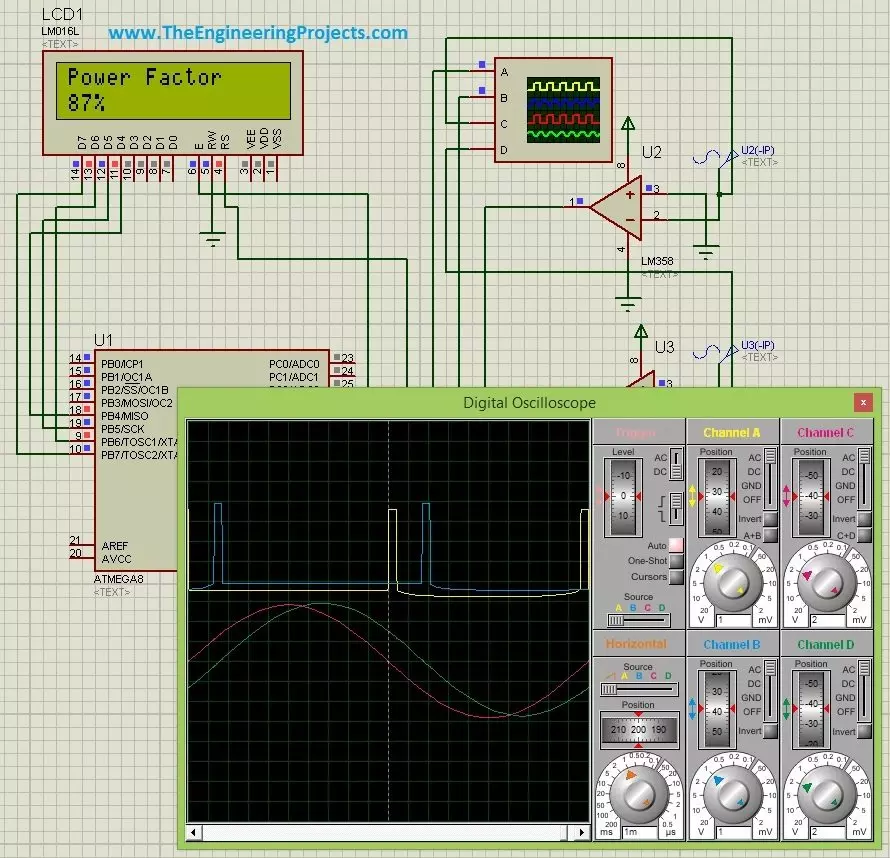
Hello friends, hope you all are fine and having fun. Today's post is about Power Factor Measurement using Microcontroller in Proteus ISIS. As usual, I have this project simulation in which I have to simulate a power factor measuring project using atmega microcontroller. So, I use atmega8 microcontroller and the used Proteus ISIS as the simulating software. Power Factor Measurement isn't that difficult but its a quite tricky and in today's post we are gonna cover it in full detail.

There are many ways for power factor measurement and today's the method we are gonna use is called zero crossing detection. We will first detect the zero crossing of our signal and then we are gonna do the power factor measurement based on the detection of zero crossing of our voltage and current signal. Seems bit difficultdon't worry we are gonna do everything and in quite full detail so stay with me and enjoy the tutorial. But before going into the details of power factor measurement, let's first discuss the basics of power factor measurement because before that you wont understand a bit.

We have designed this simulation after quite a lot of effort so its not for sale but has a quite small cost of $20 so that engineering students can buy it easily. You can buy the simulation along with hex file and code by clicking on the above button and it will lead you to Product page of this product. So, let get started with it.

Basics of Power Factor

  • In AC circuits, there are total three types of loads which are normally bear by an AC current, named as:
    • Resistive Loads.
    • Capacitive Loads.
    • Inductive Loads.

We are all quite well aware of these and if you are not then I must say you wont read further and must first get some basic knowledge about these loads. Among these three loads Resistive loads are known as the most decent loads as they don't mess up with the current and just simply let the current pass through it and that's why there's no such power loss in these types of loads. But when it comes to Capacitive or Inductive loads. they are quite disturbing types of loads and hence they don't let the current easily pass through them and slightly distort the current signals. In case of Capactive loads, the current waveform got ahead of the voltage waveform and hence got a lead angle. In other words, current waveform leads the voltage waveform. While in case of Inductive loads, the scenario is quite the opposite. In Inductive loads, current waveform lags the voltage waveform. The below figure shown the difference between these loads output.

  • In the above figure, Red waveform is showing the current wave, while the green waveform is showing the voltage wave. So its quite obvious from above three figures that in case of resistive load there's no angle difference but in case of capacitive load, current waveform leads the voltage waveform while in Inductive load current waveform lags the voltage waveform and in this case I have used a constant angle of 60 degrees for both capacitive and inductive loads.
  • Now because of this angle difference there's quite an energy loss which is not quite good for any system so the best scenario for any system is that this angle should be 0 which is the case of resistive loads.
  • Now question is why we are reading this stuff while we are actually interested in power factor measurement so yes now I am coming towards it.
  • Power Factor is simply the cosine of this leading or lagging angle. In simple words, if you get this leading or lagging angle between current and voltage waveform, which in the above figure is 60 degrees, and then take the cosine function of that angle, you will get the Power factor for your system.
  • So, if we calculate the power factor for the above waveform, for which the leading or lagging angle (both) are 60 degrees, then we get:

Power Factor = Cos ( 60 degrees )

Power Factor = 0.5

  • So, the power factor of our above system is 0.5 which is quite bad.
  • Now, whats the meaning of this 0.5 power factor, it means that our system's efficiency is 50% and the energy dissipation is also 50% so our system's efficiency is as well 50%.
  • So, if we want to improve our systems' efficiency, then we need to increase the Power Factor of our system.
So, now we have seen the basics of power factor and have got quite an idea about what is it so now let's start with how to measure power factor using Microcontroller in Proteus ISIS.

Power Factor Measurement with Zero Crossing Detection

  • There are many methods available for Power Factor measurement and in this post we are gonna use the zero crossing detection in order to measure it .
  • As we all know, the voltage and current waveform are basically the sine waves so they must cross the zero point at some time.
  • And what we need to do is to detect the zero crossing of both these waves. So, first of all we are gonna do this in Proteus.
  • So, design a circuit in Proteus for Power Factor Measurement as shown in below figure:
 
  • In the above circuit design, I have used two voltage sources which are U2 and U3, I have considered U2 as the voltage transformer while the U3 as the current transformer, when you are designing the actual circuit in hardware then you need to use the current and voltage transformer.
  • The reason why we need to use CT and PT is because the normal voltage is normally of 220V or 110V which we can't directly give to our microcontroller because it will burn our microcontroller.
  • So, we need to lower this voltage level and needs to bring it to such level which is easily operatable by microcontroller, which in normal case is below 5V.
  • So, now I suppose you have used the CT PT and you are getting your current and voltage waveforms in the order of 5V but now again there's another issue that the voltage we are getting is AC while our microcontroller works on DC so we need to find some way to convert this AC into DC.
  • So,in order to do, I have used this 8 pin amplifier LM358 as a comparator.
  • What LM358 is doing ?? Its simply comparing the voltage coming at its inverting pin to the voltage at its non inverting pin and whenever both voltages match it will send a HIGH pulse to the output.
  • You can see clearly that I have placed a GND on the non inverting pin of LM358 so whenever we get zero crossing on the inverting side it will send us a HIGH pulse at output.
  • That's how we are converting our AC signal into DC signal as well as detecting the zero crossing. Let's have a look at these waveform in Oscilloscope.
  • The below two waveform are the current and voltage waveform, red one is current while the green one is voltage and I have placed a lagging angle of 30 degrees that's why current waveform is lagging the voltage waveform.
  • While the above two waveform are the output of LM358 and we can see clearly they are giving the high peaks when the lower waveform cut their zero axis.
  • So that's how we are doing the zero crossing detection.
  • We have got the zero crossing detection and now what we are gonna do in programming is to first detect the zero crossing of current waveform and then we will start counting the time until we get the zero crossing of voltage waveform.
  • So, basically what we are gonna do is we are gonna count the time difference between current wave and voltage wave zero crossing.
  • When we got the time difference between these two waves, we can get the angle quite easily using the below formula.
  • We have got the time difference and we have already know the frequency of our system which is normally 50 HZ or 60Hz.

Power Factor Measurement Using Microcontroller in Proteus

  • Now we have already detected the zero crossing so now next thing is to calculate the time difference which we are gonna do in our microcontroller.
  • So, in order to do the time calculation, first of all we will detect the zero crossing of current wave.
  • Then we will start a timer which will start counting and we will stop this counting when we get the voltage curve.
  • So, in order to do these tasks, I have used the below code:
void pf_func(){
while(1)
{
       if ( PINC.4==1 )
       {
           TCNT1=0;
           TCCR1B = 0x01;
           break;
       }
       else {
               continue;
             }
}
while(1){
     if ( PINC.3 == 1 ){
     TCCR1B = 0x00;
     g=TCNT1;
     break;
}
else {
continue;
}
}
}
  • Now, when we detect the zero crossing of current waveform, we simply start the timer and start counting and when we get the zero crossing of voltage waveform, we simply stop the counter and we get the total time difference between the current waveform and the voltage waveform.
  • Now, next thing we need to do is to calculate the power factor, which is now quite easy because we already got the time difference.
  • So, what I do in order to do that is simply used the below simple code:
int powerfactor(){
k=0;
// To complete number of counts
g=g+1; //Value from the timer
//To convert into seconds
pf=(float)g/1000000;
//To convert into radians
pf=pf*50*360*(3.14/180);
//power facor
pf = cos(pf);
//power factor into percentage
k=abs(ceil(pf*100));
return k;
}
  • So, that's how we are calculating the Power factor.
  • We have done quite a lot of effort to design this simulation and code so its not for free but you can getit easily just for a price of $20.
  • Now when you get the code then make your hex file and upload it in Proteus.
  • Now run your Proteus simulation and you will get something like this:
  • In the above figure, current waveform leads the voltage waveform by 30 degrees and that's why we are getting a power factor of 0.87 which is 87%.
  • Now let me reduce the difference between current and voltage waveform to 0 and we will get a power factor of 1 as shown below:
  • Now, you have seen as we reduced the distance between current and voltage waveform the power factor has increased and as the angle between current and voltage waveform is 0 so its 100%.
That's all for today, I hope you have enjoyed today's post on Power Factor Measurement. You can buy the complete simulation along with hex file and the complete code by clicking on below button.

Buy Power Factor Simulation

So, buy it and test it and hopefully you will get something big out of it. So that's all about Power Factor Measurement using Atmega. I will post it on Arduino as well quite soon and may be on PIC Microcontroller as well. So, till next tutorial take care !!! :)

Syed Zain Nasir

I am Syed Zain Nasir, the founder of <a href=https://www.TheEngineeringProjects.com/>The Engineering Projects</a> (TEP). I am a programmer since 2009 before that I just search things, make small projects and now I am sharing my knowledge through this platform.I also work as a freelancer and did many projects related to programming and electrical circuitry. <a href=https://plus.google.com/+SyedZainNasir/>My Google Profile+</a>

Share
Published by
Syed Zain Nasir