Hello friends! Today, we are going to study serial communication with an 8051 microcontroller in Proteus. We will send characters from a Virtual Terminal to an AT89C52, use those characters to control eight LEDs and send a short acknowledgement back to the terminal. If you have completed our 8051 LED blinking project , you already know how to build the basic circuit and load a HEX file. This tutorial adds a communication channel so the output changes in response to a command instead of a fixed delay. We will keep the original command scheme and project download, while correcting an important clock detail. The revised program uses an 11.0592 MHz oscillator for 9600 baud. The older screenshots show a 16 MHz crystal, so change that value and the processor clock setting when following the prog ...
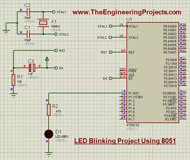
Hello friends! Today, we are going to build an LED blinking project using an 8051 microcontroller in Proteus. This is a useful first exercise because it connects a short C program with something we can immediately observe: an output pin repeatedly switching an LED on and off. We will use the AT89C52, which belongs to the 8051 family, and keep the original project's 16 MHz clock and P1.0 LED connection. I will explain the supporting circuit first, then show how to create the program in Keil, generate a HEX file and load it into the simulation. The original simulation and download remain available below. The updated example uses Timer0 for an understandable delay instead of relying on an empty software loop. That gives us a practical introduction to both digital outputs and the relationship ...
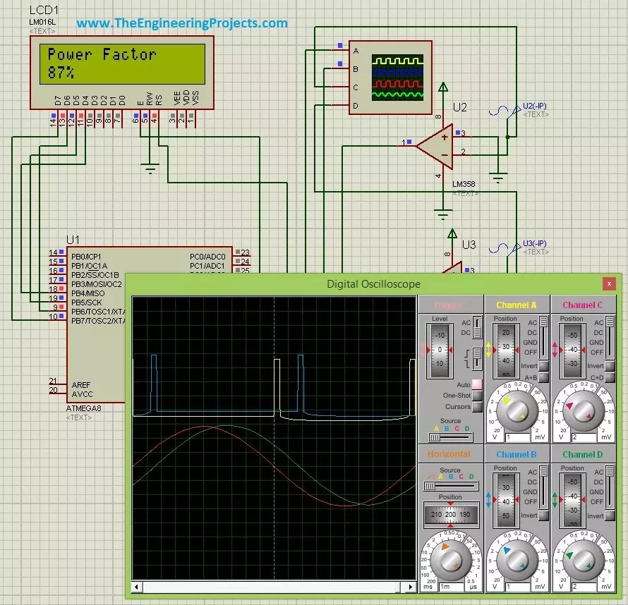
Hello friends! Today, we are going to discuss power factor measurement using a microcontroller in Proteus. We will use the ATmega8 project to understand how the timing difference between voltage and current can be converted into a phase angle, and then into a power factor reading on an LCD. I will start with the electrical meaning of power factor, because a correct calculation is useful only when we understand what it measures. After that, we will examine the zero-crossing stages, choose a timer resolution, work through numerical examples and discuss the changes needed for reliable firmware. The circuit is an educational simulation using separate signals to represent voltage and current. Its timing method is appropriate for sinusoidal waveforms. When a load draws distorted current, we need ...