Now, today we are gonna go a little further and will have a look at Serial Communication with 8051 Microcontroller and we will also design the simulation of this project in Proteus ISIS software. 8051 Microcontroller also supports Serial port similar to Arduino and PIC Microcontroller. And the communication protocol is exactly the same as its a Serial Port. But obviously the syntax is bit different as we are not working in Arduino software or MPLAB. So let's get started with it.
Serial Communication with 8051 Microcontroller in Proteus
- Let's first have a little recall of Serial communication. In serial communication we have two pins which are named as TX and RX.
- TX pin is used for transmitting data while the RX pin is used for receiving data.
- So, our microcontroller has these two pins as it supports Serial Communication and these pins are located at Pin no 10 and 11 in AT89C52 Microcontroller, which I am gonna use today.
- First of all, we will design a Simulation of this project in which there will be 8 LEDs attached to Port 1 and by sending characters through Serial port, we will either turn these LEDs ON or OFF.
- After designing the Simulation, we will then design the programming code for 8051 Microcontroller and will test our result.
- So, let's get started with Proteus Simulation of Serial Communication with 8051 Microcontroller.
Proteus Simulation
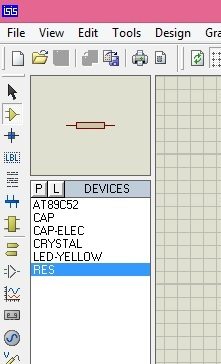
- Open your Proteus software and get these components from your Proteus Component Library:
- Now, design a circuit for Serial Communication with 8051 Microcontroller in Proteus software as shown in below figure:
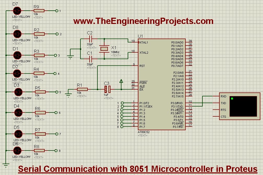
- Now in the above figure, I have used crystal Oscillator of 16MHz as I did in the previous post LED Blinking Project using 8051 Microcontroller and again the reset is pull Down.
- Next I have attached Virtual Terminal with TX and RX of 8051 Microcontroller, if you don't know about Virtual Terminal much then I suggest to read How to use Virtual Terminal in Proteus ISIS.
- Finally, I have attached the 8 LEDs on Port 1 so that we could check whether we are getting correct data or not.
- Now let's design the programming code.
Programming Code
- Now open your Keil micro vision 4 software and paste the below code into it.
#include <reg52.h>

#define Baud_rate 0xFD  // BAUD RATE 9600

void SerialInitialize(void);
void SendByteSerially(unsigned char);
void cct_init(void);

sbit Appliance1 = P1^0;
sbit Appliance2 = P1^1;
sbit Appliance3 = P1^2;
sbit Appliance4 = P1^3;
sbit Appliance5 = P1^4;
sbit Appliance6 = P1^5;
sbit Appliance7 = P1^6;
sbit Appliance8 = P1^7;


void main()
{
    cct_init();
    SerialInitialize();

    EA = 1;
    ES = 1;

    while(1) {;}
}


void cct_init(void)   //initialize cct
{
    P0 = 0x00; //not used
    P1 = 0x00; //Used for Appliances
    P2 = 0x00; //not used
    P3 = 0x03; //used for serial

}

void SerialInitialize(void)                   // INITIALIZE SERIAL PORT
{
    TMOD = 0x20;                           // Timer 1 IN MODE 2 -AUTO RELOAD TO GENERATE BAUD RATE
    SCON = 0x50;                           // SERIAL MODE 1, 8-DATA BIT 1-START BIT, 1-STOP BIT, REN ENABLED
    TH1 = Baud_rate;                       // LOAD BAUDRATE TO TIMER REGISTER
    TR1 = 1;                               // START TIMER
}

void SendByteSerially(unsigned char serialdata)
{
    SBUF = serialdata;                        // LOAD DATA TO SERIAL BUFFER REGISTER
    while(TI == 0);                            // WAIT UNTIL TRANSMISSION TO COMPLETE
    TI = 0;                                    // CLEAR TRANSMISSION INTERRUPT FLAG
}

void serial_ISR (void) interrupt 4
{
    //receive character
    char chr;
    if(RI==1)
    {
        chr = SBUF;
        RI = 0;
    }

    P0 = ~P0;    //Show the data has been updated

    switch(chr)
    {
     case '1':  Appliance1 = 1; SendByteSerially('k');  break;
     case '2':  Appliance2 = 1; SendByteSerially('k');  break;
     case '3':  Appliance3 = 1; SendByteSerially('k');  break;
     case '4':  Appliance4 = 1; SendByteSerially('k');  break;
     case '5':  Appliance5 = 1; SendByteSerially('k');  break;
     case '6':  Appliance6 = 1; SendByteSerially('k');  break;
     case '7':  Appliance7 = 1; SendByteSerially('k');  break;
     case '8':  Appliance8 = 1; SendByteSerially('k');  break;


     case 'a':  Appliance1 = 0; SendByteSerially('k');  break;
     case 'b':  Appliance2 = 0; SendByteSerially('k');  break;
     case 'c':  Appliance3 = 0; SendByteSerially('k');  break;
     case 'd':  Appliance4 = 0; SendByteSerially('k');  break;
     case 'e':  Appliance5 = 0; SendByteSerially('k');  break;
     case 'f':  Appliance6 = 0; SendByteSerially('k');  break;
     case 'g':  Appliance7 = 0; SendByteSerially('k');  break;
     case 'h':  Appliance8 = 0; SendByteSerially('k');  break;


     default: ;    break;     //do nothing
    }

    RI = 0;
}
- You can see in the above code that baud rate we have used is 9600and we have used a switch case method for turning ON or OFF Leds.
- So, now what it will do is when you send 1 on Serial Monitor, it will turn ON the first LED and when you send "a" on Serial Terminal then it will turn OFF the first LED. The same will go on for 8 LEDs.
- Character 1,2,3,4,5,6,7,8 will turn ON the LEDs from 1 to 8 respectively.
- While the character a,b,c,d,e,f,g,h will turn OFF the LEDs from 1 to 8 respectively.
- For each command it will reply us back a single character which is "k". So in this way we are doing the two way communication i.e. sending as well as receiving the serial data.
- So, now after adding the code, get your hex file and then upload it to your Proteus Simulation and click the RUN button on your Proteus software.
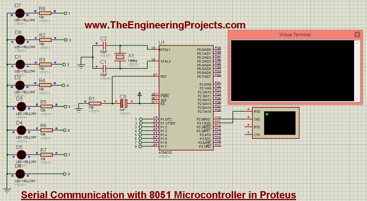
- When you start your Proteus Simulation, all the LEDs will be OFF and the virtual terminal will be open as shown in below figure:
- So, now click in the Virtual Terminal and press 1 and the first LED will get ON and you will get k in response as shown in below figure:
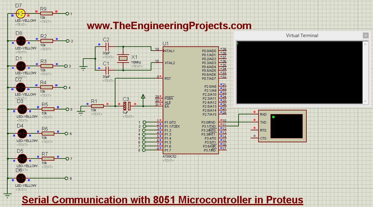
- You can see in the above figure, I have pressed 1 and the first LED goes ON as well as we get a response "k" in the virtual Terminal.
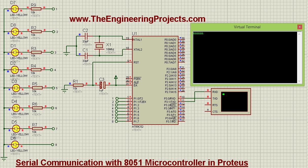
- So, that's how we can turn ON or OFF LEDs so in the below figure, I have turned ON all the 8 LEDs.

- Now you can see in the above figure,all leds are on and the virtual terminal is showing k for 8 times as I have given 8 instructions.
- You can download the Proteus Simulation along with hex file and the programming code by clicking the below button.


 8051 Microcontroller Projects
 syedzainnasir
 5 Comments


 2.3k
2.3k
 953
953
 921
921
 2.1K
2.1K


