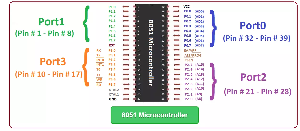
Hello Friends! Hope you are doing great. I am back to give you a daily dose of valuable information so you can excel and grow in your relevant field and keep coming back for what we have to offer. Today, I am going to unlock the details on the Introduction to 8051 Microcontroller. This is an 8-bit Microcontroller developed by Intel in the 1980s. It is considered as a small system on an integrated chip that comes with CPU, I/O ports, timers, counters, RAM and ROM. The Microcontroller is a one step forward to a microprocessor. Both Microcontrollers and microprocessor work in a similar way with some exceptions. Microcottler comes with everything required to run an embedded system like CPU, I/O ports and inbuilt peripherals like timers, counters, and interrupts. While processor comes with the ...
Hello friends! Today, we will generate a PWM signal with an 8051 microcontroller and inspect it in Proteus. We will begin with frequency and duty cycle, then use Timer 0 interrupts to control P2.0 without placing a long delay in the main program. The original project demonstrates software-generated PWM, which is useful for a classic device such as the AT89C51 that does not provide a dedicated PWM peripheral. Other 8051-compatible devices can include hardware PWM, so check the exact processor before deciding that software generation is necessary. We will keep the original circuit, waveforms and download, but make the timing assumptions and endpoint behavior explicit. The revised example uses a fixed timer interval and twenty duty steps, making the relationship between interrupt rate, PWM fr ...
Hello friends! In this project, we will build an interrupt-based digital clock with an 8051 microcontroller and display the time on a character LCD. A hardware timer will provide the timing events, while the main program handles the display. We will start with the timer calculation, then build the seconds, minutes and hours counters. We will also correct two problems that commonly appear in beginner clocks: using the wrong timer reload and reading shared time counters while an interrupt is changing them. The original circuit images and downloadable project remain attached. The revised example assumes a classic twelve-clock 8051 running at 12 MHz. It starts at 00:00:00 after initialization and demonstrates elapsed-time counting; it does not retain the time when power is removed. Figure: Int ...
Hello friends! In this tutorial, we will use timer interrupts in an 8051 microcontroller to generate a regular output without placing a delay in the main loop. We will start with Timer 0, calculate its reload value and observe the resulting signal in Proteus. We will then repeat the example with Timer 1 and discuss how to turn a short hardware interval into a slower application task. The calculations below assume a classic twelve-clock 8051 timer and a 12 MHz oscillator. Check those assumptions whenever you select a different 8051-compatible device. The original simulations and screenshots remain attached. One detail in the earlier example needs correction: loading 5 into an eight-bit timer produces 251 counts before overflow, not 250. The revised code uses 6 for a nominal 250-microsecond ...
Hello friends! This page brings our 8051 microcontroller projects together in a learning sequence. We will begin with an LED and a serial connection, then move through displays, keypads, timers and complete applications. Each linked tutorial provides the details for its own circuit and program. The purpose of this collection is to help you choose a useful next project, rather than download several unrelated simulations without understanding them. A small circuit that you can explain, modify and troubleshoot teaches more than a large circuit that only works with an unchanged HEX file. We will also discuss the practical decisions behind these projects: selecting the exact processor, matching its clock, allocating pins and checking timing. Those details determine whether examples can be combi ...
Hello friends! Today, we will interface a seven-segment display with the 8051 microcontroller and use it to show the digits zero through nine. This is a useful first display project because you can trace every visible segment back to one output bit in your program. We will use the AT89C51 and examine the original Proteus circuit with its 74LS245 buffer. Before writing the code, we will identify the display type, build a digit table and calculate the timing. We will also correct an important issue in the historical schematic: LED segments need individual current-limiting resistors. The original screenshots and project download remain available below. They are useful references for the simulation, but some details need care when moving to hardware. In particular, the displayed circuit and ac ...
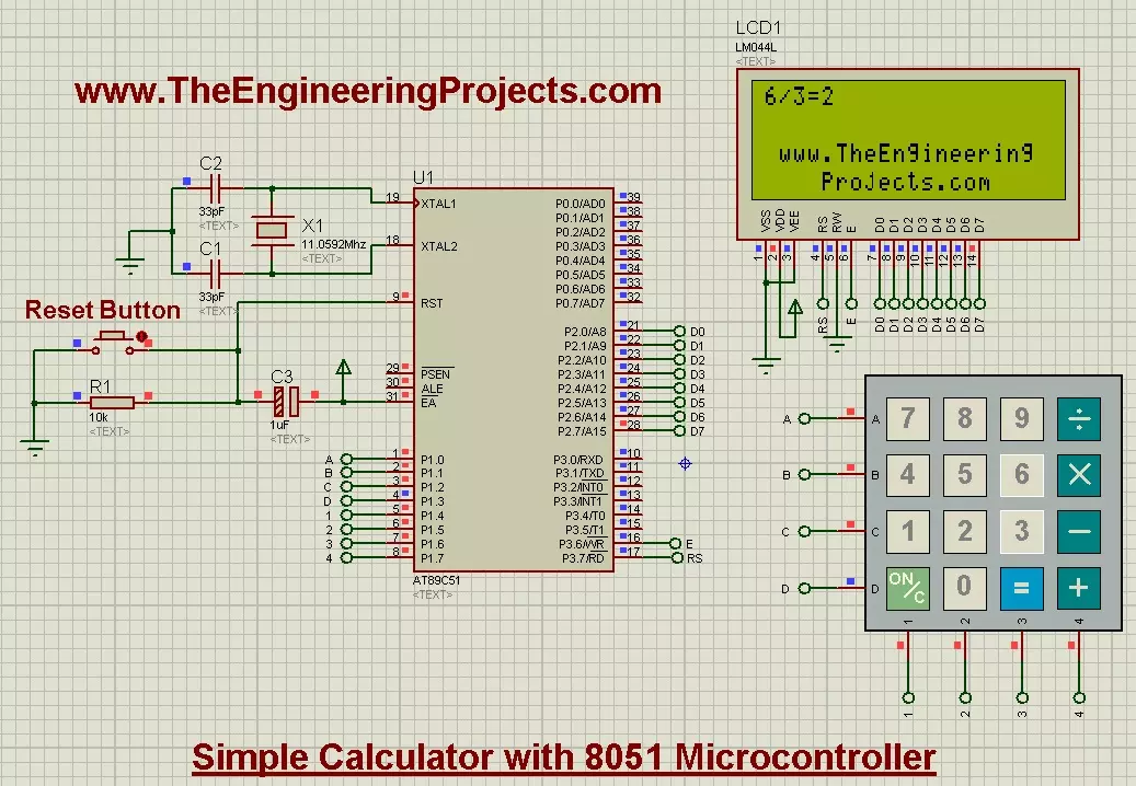
Hello friends! Today, we are going to design a simple calculator with an 8051 microcontroller in Proteus. We will combine a 4×4 keypad, a 20×4 LCD and an AT89C51 so that you can enter an arithmetic operation and see its result on the display. We have already covered LCD interfacing and keypad interfacing with the 8051 . Those lessons provide the input and output functions. Here, we will add the application logic that decides which key is valid and when a calculation should take place. This remains a single-digit calculator, like the original project. It accepts two operands from zero through nine and supports addition, subtraction, multiplication and integer division. We will also handle negative results, invalid input and division by zero explicitly. Figure: Original 8051 calculator showi ...
Hello friends! Today, we are going to interface a 4×4 keypad with an 8051 microcontroller in Proteus. We will read the pressed key through the AT89C51 and display its character on a 20×4 LCD, so we can see exactly what the program receives. This project builds on our LCD interfacing tutorial . The display remains our output device, while the keypad becomes an input device. Together, they form the basic user interface for a calculator, menu, password entry system or small control panel. I will explain the keypad matrix before discussing the program. We will then add debouncing, prevent one held button from producing repeated characters and keep typed text within the upper two LCD rows. The original simulation, images and download are preserved for reference. Figure: Original keypad characte ...
Hello friends! Today, we are going to interface a character LCD with an 8051 microcontroller in Proteus. We will use an AT89C51 to send commands and text to the display, then explain how the LCD decides where each character should appear. This is the next step after our 8051 serial communication tutorial . A serial terminal is useful during development, while an LCD lets a project present information directly to its user. Both are valuable when we need to observe values inside an embedded program. The original project actually uses an LM044L-style 20×4 display, so we will follow that arrangement throughout this lesson. A 20×4 LCD has twenty character positions on each of four rows. The same interface principles apply to many 16×2 modules, but their visible layout and row handling are diffe ...
Hello friends! Today, we are going to study serial communication with an 8051 microcontroller in Proteus. We will send characters from a Virtual Terminal to an AT89C52, use those characters to control eight LEDs and send a short acknowledgement back to the terminal. If you have completed our 8051 LED blinking project , you already know how to build the basic circuit and load a HEX file. This tutorial adds a communication channel so the output changes in response to a command instead of a fixed delay. We will keep the original command scheme and project download, while correcting an important clock detail. The revised program uses an 11.0592 MHz oscillator for 9600 baud. The older screenshots show a 16 MHz crystal, so change that value and the processor clock setting when following the prog ...