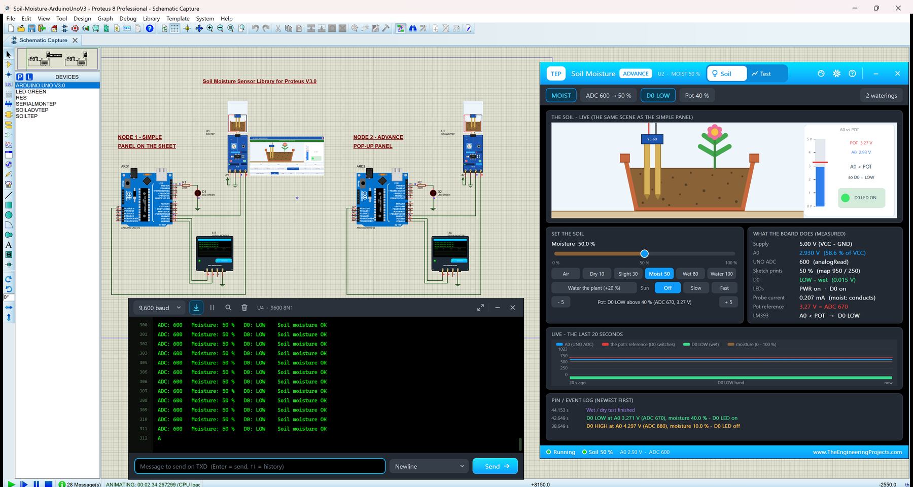
Hello friends, I hope you all are doing great. Today, I am going to share the new Soil Moisture Sensor Library for Proteus V3.0 . The soil moisture sensor is one of the first sensors students use in a garden or agriculture project: a YL-69 fork probe that you push into the soil, and the blue FC-28 board with an LM393 comparator that gives an analog output (A0) and a digital output (D0). With this Soil Moisture Sensor Library for Proteus , you set the soil with a click, water the plant, let the sun dry it, and your Arduino reads A0 with analogRead() and D0 with digitalRead(), just like on a real board. Updates Soil Moisture Sensor Library for Proteus Latest version: V3.0 (October 2026, this tutorial) Earlier versions: V2.0 (2021) · V1.0 (2020) Other water and soil sensors: Capacitive Soil · ...
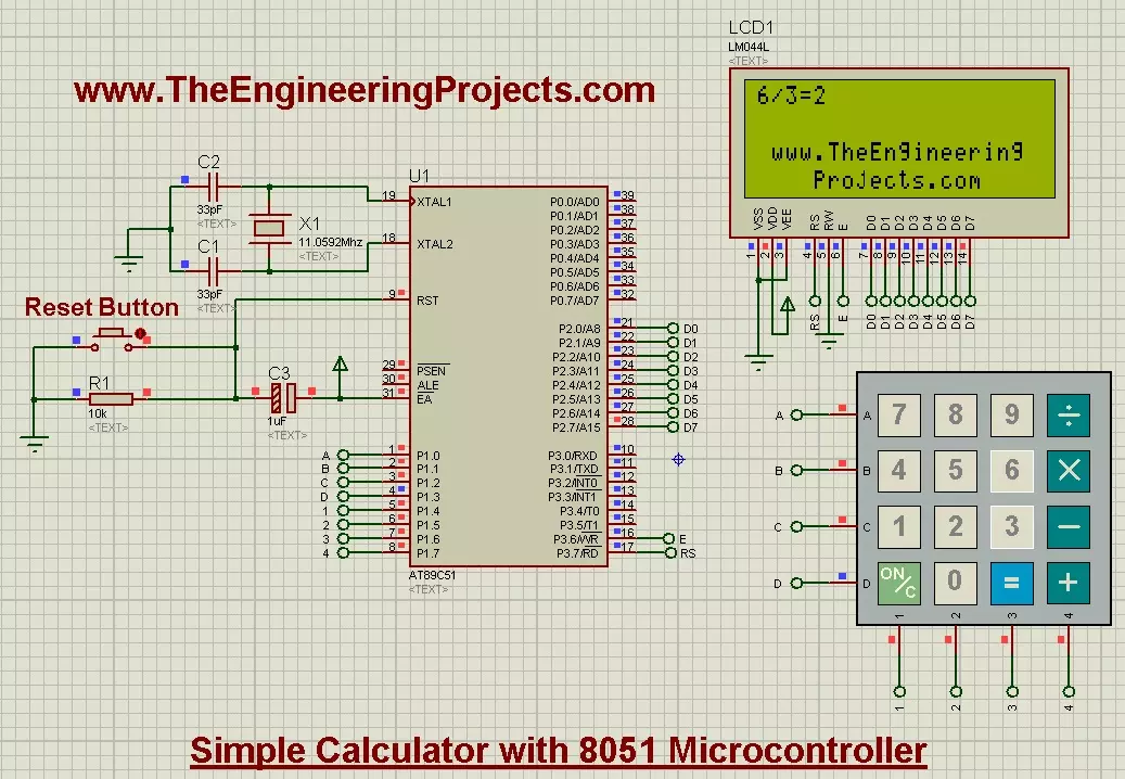
Hello friends! Today, we are going to design a simple calculator with an 8051 microcontroller in Proteus. We will combine a 4×4 keypad, a 20×4 LCD and an AT89C51 so that you can enter an arithmetic operation and see its result on the display. We have already covered LCD interfacing and keypad interfacing with the 8051 . Those lessons provide the input and output functions. Here, we will add the application logic that decides which key is valid and when a calculation should take place. This remains a single-digit calculator, like the original project. It accepts two operands from zero through nine and supports addition, subtraction, multiplication and integer division. We will also handle negative results, invalid input and division by zero explicitly. Figure: Original 8051 calculator showi ...
Hello friends! Today, we are going to interface a 4×4 keypad with an 8051 microcontroller in Proteus. We will read the pressed key through the AT89C51 and display its character on a 20×4 LCD, so we can see exactly what the program receives. This project builds on our LCD interfacing tutorial . The display remains our output device, while the keypad becomes an input device. Together, they form the basic user interface for a calculator, menu, password entry system or small control panel. I will explain the keypad matrix before discussing the program. We will then add debouncing, prevent one held button from producing repeated characters and keep typed text within the upper two LCD rows. The original simulation, images and download are preserved for reference. Figure: Original keypad characte ...
Hello friends! Today, we are going to interface a character LCD with an 8051 microcontroller in Proteus. We will use an AT89C51 to send commands and text to the display, then explain how the LCD decides where each character should appear. This is the next step after our 8051 serial communication tutorial . A serial terminal is useful during development, while an LCD lets a project present information directly to its user. Both are valuable when we need to observe values inside an embedded program. The original project actually uses an LM044L-style 20×4 display, so we will follow that arrangement throughout this lesson. A 20×4 LCD has twenty character positions on each of four rows. The same interface principles apply to many 16×2 modules, but their visible layout and row handling are diffe ...
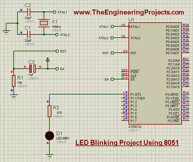
Hello friends! Today, we are going to build an LED blinking project using an 8051 microcontroller in Proteus. This is a useful first exercise because it connects a short C program with something we can immediately observe: an output pin repeatedly switching an LED on and off. We will use the AT89C52, which belongs to the 8051 family, and keep the original project's 16 MHz clock and P1.0 LED connection. I will explain the supporting circuit first, then show how to create the program in Keil, generate a HEX file and load it into the simulation. The original simulation and download remain available below. The updated example uses Timer0 for an understandable delay instead of relying on an empty software loop. That gives us a practical introduction to both digital outputs and the relationship ...
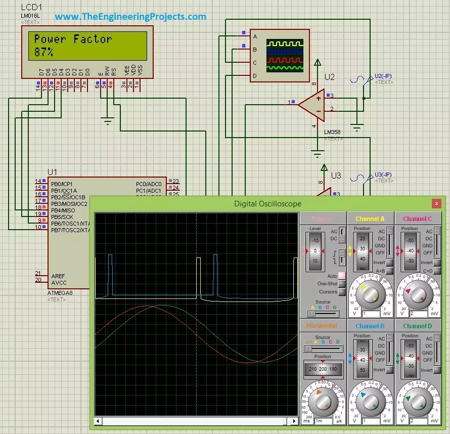
Hello friends! Today, we are going to discuss power factor measurement using a microcontroller in Proteus. We will use the ATmega8 project to understand how the timing difference between voltage and current can be converted into a phase angle, and then into a power factor reading on an LCD. I will start with the electrical meaning of power factor, because a correct calculation is useful only when we understand what it measures. After that, we will examine the zero-crossing stages, choose a timer resolution, work through numerical examples and discuss the changes needed for reliable firmware. The circuit is an educational simulation using separate signals to represent voltage and current. Its timing method is appropriate for sinusoidal waveforms. When a load draws distorted current, we need ...
Hello friends! In this tutorial, we will design an LED blinking project using the PIC16F877A microcontroller. It is a simple project, but it introduces several ideas that appear in almost every embedded system: configuring an I/O port, choosing an oscillator, building a reset circuit, calculating LED resistors, generating a time delay, compiling a program, and loading the resulting HEX file into Proteus. We will connect eight LEDs to PORTB and switch the complete port between logic low and logic high. Once this basic version works, you can change the output patterns and timing to create a running light, binary counter, or status display. The important objective is to understand why every connection and every program statement is present. Figure: The original simulation shows the PORTB LED ...