Introduction to 2n6491

Hello Friends! Hope you are doing great. We always come up with useful information that helps you solve your problems and keeps you updated with the knowledge that resonates with your needs and demands. Today, I am going to unlock the details on the Introduction to 2n6491. It is an NPN power transistor mainly used for general purpose amplification and switching purpose. It exhibits high DC current gain and comes with TO-220 package. I'll break down all information related to this transistor in easy steps, so you can grab the main concept easily. Let's dive in and explore what is this about and its main applications.

Introduction to 2n6491

  • 2n6491 is an NPN (negative-positive-negative) bipolar junction transistor mainly used for general purpose amplification and switching purpose.
  • It has three terminals used for external connection with the electronic circuits called emitter, base, and collector.
  • All these three terminals are different in terms of their doping concentration. An emitter is highly doped as compared to base and collector.
  • The base is lightly doped which is responsible to trigger the electron reaction in the transistor.
  • The collector is moderately doped which is used to collect the electors from base terminals.
  • When a voltage is applied at the base terminals, it gets triggered and starts the electron reaction.
  • The base terminal then draws small current which is used to control large current at the collector and emitter side.
  • This transistor is a current controlled device where small current at the base side is used to control the large current at the other terminals.
  • The number of electrons from emitter side is diffused to the base side where they act as minority carriers. Holes behave as majority carriers at the base side.
  • When electrons come from the emitter side, it will combine with the holes in the base terminal.
  • However, a base cannot control all number collected from the emitter side, resulting to diffuse the remaining electrons to the collector side.
  • Diode plays a vital role in the construction of this transistor. When two diodes are joined back to back, they constitute a transistor.
2n6491 Pinout
  • The following figure shows the pinout of this NPN transistor. It consists of three terminals called emitter, base, collector.
  • Free movement of electrons from a base to collector terminal occurs when a voltage is applied at the base terminal. Actually, movement of electrons is nothing but a bridge between emitter and collector.
Circuit Diagram of 2n6491
  • Following figure shows the circuit diagram of this NPN transistor.
  • The voltage at the base side is positive with respect to the emitter and current flows from the emitter to collector.
  • The amount of current we get at the output side is highly dependent on the small current at the base side which is the result of the voltage applied at the base terminal.
  • The emitter current is equal to the sum of base and collector current because doping concentration of emitter is more than base and collector, resulting in a more current present at the emitter terminal as compared to other terminals.
  • Common emitter current gain is an important factor determining the characteristics of the transistor. It is the ability of current being amplified. It is called beta and denoted by ß which is a ratio between collector current and base current. Beta plays an important role in the amplification purpose and also known as an amplification factor.
  • Similarly, the common-base current gain is another important factor which is obtained when base to collector voltage is constant. It is called alpha and denoted by a. It is a ratio between collector current and emitter current. The alpha value is always less than one and lies between 0.95 and 0.99. However, more often than not, alpha value is taken as unity.
  • This NPN transistor contains electrons as majority charge carriers while PNP transistors contain holes as majority charge carriers.
Absolute Maximum Ratings
  • Following figure shows the absolute maximum ratings of 2n6491.
  • These are the stress ratings which, if exceed from the absolute maximum ratings, can damage the device at large.
  • If these ratings are applied for the maximum period of time, they can affect the device reliability.
  • We can see from the figure, collector-emitter voltage is 80 and collector-base voltage is 90.  And maximum power dissipation is 75 W.
  • It is important to consider these absolute maximum ratings before you pick this transistor for your project. These ratings play a vital role in the execution and performance of the whole project.
  • If ratings of this transistor don't match with your requirements, then you can try other transistors like 2n3903 that comes with different ratings.
Applications
  • This transistor is mainly used for general purpose amplification.
  • Fast switching applications involve this transistor.
That's all for today. You must have a look at MOSFET which is a unipolar voltage controlled device different than this NPN transistor which is a current controlled bipolar device. If you're unsure or have any question, you can ask me in the comment section below. I'd love to guide you according to best of my expertise in any way I can. Keep us updated with your valuable suggestions, they allow us to give you quality work that aligns with your needs and demands. Thanks for reading the article.

How to Create PWM in Raspberry Pi 3

Hello friends, I hope you all are doing great. In today's tutorial, I am going to explain How to Create PWM in Raspberry Pi 3. In our previous tutorial, we have seen How to Create GUI in Raspberry Pi 3, & we have also controlled an LED from the GUI Buttons. So, I am gonna take that project and will add PWM code in it. So, I would recommend you to first have a look at LED Blinking with Raspberry Pi 3 in which we have designed this simple project and then check How to Create GUI in Raspberry Pi 3, where we have controlled that LED digitally with GUI. But today, we are gonna control the intensity of this LED by creating a PWM Pulse in Raspberry Pi 3. Along with that, we are also gonna have a look at How to use Scale in Raspberry Pi 3. I will add a new scale in the same GUI and when we change the value of this scale and the LED intensity will also change. So, let's get started with How to Create PWM in Raspberry Pi 3:

Create PWM in Raspberry Pi 3

  • In our previous post, we have created a simple GUI to control an LED, that GUI is shown in below figure:
  • I hope you have remembered the Grid system which we discussed in last lecture, we are now gonna add a new scale in our GUI and we will place it at row = 1 & column = 2.
  • It's on the right side of 'LED OFF' button. Here's the code for it.
Scale1 = Scale(Gui, from_=0, to=100, orient = HORIZONTAL, resolution = 1, command = ChangePWM)
Scale1.grid(row=1,column=2)
  • We have created a new slider and it's value starts from 0 and it ends at 100.
  • Its orientation is horizontal, by default its vertical.
  • We have assigned it a function named as ChangePWM and this function will execute whenever we change the value of this slider.
  • As, we haven't yet created the function so if you will change its value then it will give error.
  • If you run it, it will look something as shown in below figure:
  • I have given it a value from 0 to 100 because our PWM pulse value also goes from 0% to 100%.
  • If you don't know much about PWM then you should have a look at How to use Arduino PWM Pins, just read the PWM part I have discussed it in detail there.
  • In raspberry Pi 3, we have Pin # 12 and Pin # 32 as PWM Pins but I have tried different I/O Pins and this PWM commands works quite fine on all of them. :P
  • Anyways, I am going to use Pin # 12 of pi 3 so change this value from 11 to 12.
  • So, first of all we are gonna create our PWM frequency, which I have set to 5000.
  • After that I have started my PWM Pulse with a value of 0.
PwmValue = GPIO.PWM(LED, 5000)
PwmValue.start(0)
  • As you can see in above code our PwmValue is 0 so which means our LED will remain OFF.
  • Now, we have to create our slide function ChangePWM.
  • So, add the below code after your Buttons functions:
def ChangePWM(self):
    PwmValue.ChangeDutyCycle(Scale1.get())

  • Just make sure to add this self in functions' name.
  • Slide function works a little different than Button function, so we have to add this self. If you have ever worked on embedded then we add (void). :P
  • ChangeDutyCycle is the command to change duty cycle of our PWM Pulse.
  • So, we are simply getting value of our Scale and then giving this value to our pwm pulse which in turn changes the intensity of our LED.
  • So, if we have 0 on slider then our LED will be at lowest intensity so means OFF and at 100 it will glow at maximum intensity or 5V.
  • Here's our complete code:
# ************************************************************************** #
# ****                                                                  **** #
# *********** Code Designed by www.TheEngineeringProjects.com ************** #
# ****                                                                  **** #
# ****************** How to Create a GUI in Raspberry Pi 3 ***************** #
# ****                                                                  **** #
# ************************************************************************** #

# Importing Libraries

import RPi.GPIO as GPIO
import time
from tkinter import *
import tkinter.font

# Libraries Imported successfully

# Raspberry Pi 3 Pin Settings

LED = 12 # pin12
GPIO.setwarnings(False)
GPIO.setmode(GPIO.BOARD) # We are accessing GPIOs according to their physical location
GPIO.setup(LED, GPIO.OUT) # We have set our LED pin mode to output
GPIO.output(LED, GPIO.LOW) # When it will start then LED will be OFF

PwmValue = GPIO.PWM(LED, 5000)
PwmValue.start(0)

# Raspberry Pi 3 Pin Settings

# tkinter GUI basic settings

Gui = Tk()
Gui.title("GUI in Raspberry Pi 3")
Gui.config(background= "#0080FF")
Gui.minsize(800,300)
Font1 = tkinter.font.Font(family = 'Helvetica', size = 24, weight = 'bold')

# tkinter simple GUI created

def ledON():
    GPIO.output(LED, GPIO.HIGH) # led on
    Text2 = Label(Gui,text=' ON ', font = Font1, bg = '#0080FF', fg='green', padx = 0)
    Text2.grid(row=0,column=1)

def ledOFF():
    GPIO.output(LED, GPIO.LOW) # led off
    Text2 = Label(Gui,text='OFF', font = Font1, bg = '#0080FF', fg='red', padx = 0)
    Text2.grid(row=0,column=1)

def ChangePWM(self):
    PwmValue.ChangeDutyCycle(Scale1.get())

Text1 = Label(Gui,text='LED Status:', font = Font1, fg='#FFFFFF', bg = '#0080FF', padx = 50, pady = 50)
Text1.grid(row=0,column=0)

Text2 = Label(Gui,text='OFF', font = Font1, fg='#FFFFFF', bg = '#0080FF', padx = 0)
Text2.grid(row=0,column=1)

Button1 = Button(Gui, text=' LED ON', font = Font1, command = ledON, bg='bisque2', height = 1, width = 10)
Button1.grid(row=1,column=0)

Button2 = Button(Gui, text=' LED OFF', font = Font1, command = ledOFF, bg='bisque2', height = 1, width = 10)
Button2.grid(row=1,column=1)

Scale1 = Scale(Gui, from_=0, to=100, orient = HORIZONTAL, resolution = 1, command = ChangePWM)
Scale1.grid(row=1,column=2)

Text3 = Label(Gui,text='www.TheEngineeringProjects.com', font = Font1, bg = '#0080FF', fg='#FFFFFF', padx = 50, pady = 50)
Text3.grid(row=2,columnspan=2)

Gui.mainloop()
  • You can download this PWM code by clicking the below button:

[dt_default_button link="https://www.theengineeringprojects.com/RaspberryPi3/How to Create PWM in Raspberry Pi 3.rar" button_alignment="default" animation="fadeIn" size="medium" default_btn_bg_color="" bg_hover_color="" text_color="" text_hover_color="" icon="fa fa-chevron-circle-right" icon_align="left"]Download PWM Pulse Code for Raspberry Pi 3[/dt_default_button]

  • So, now let's run our code and get the results. I have shared the below image in which I have set the value of scale to 15.
So, that was all about How to Create PWM in Raspberry Pi 3. In our coming tutorial, we are gonna have a look at How to Control Direction & Speed of Dc Motor with Raspberry Pi 3. So, will meet you guys in next tutorial. Till then take care and have fun !!! :)

How to Create a GUI in Raspberry Pi 3

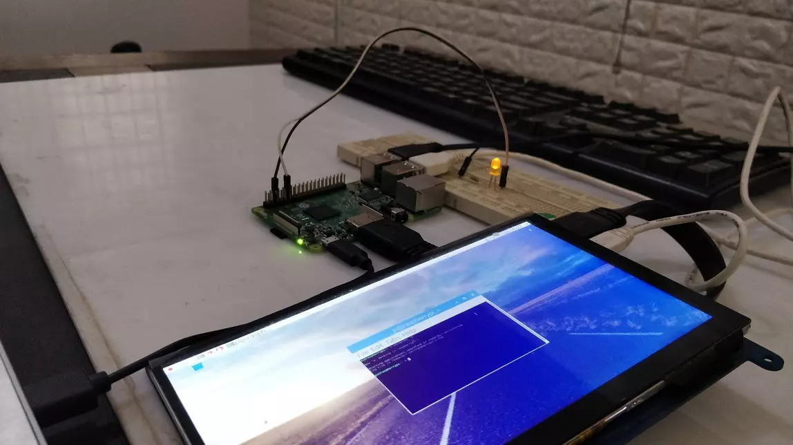
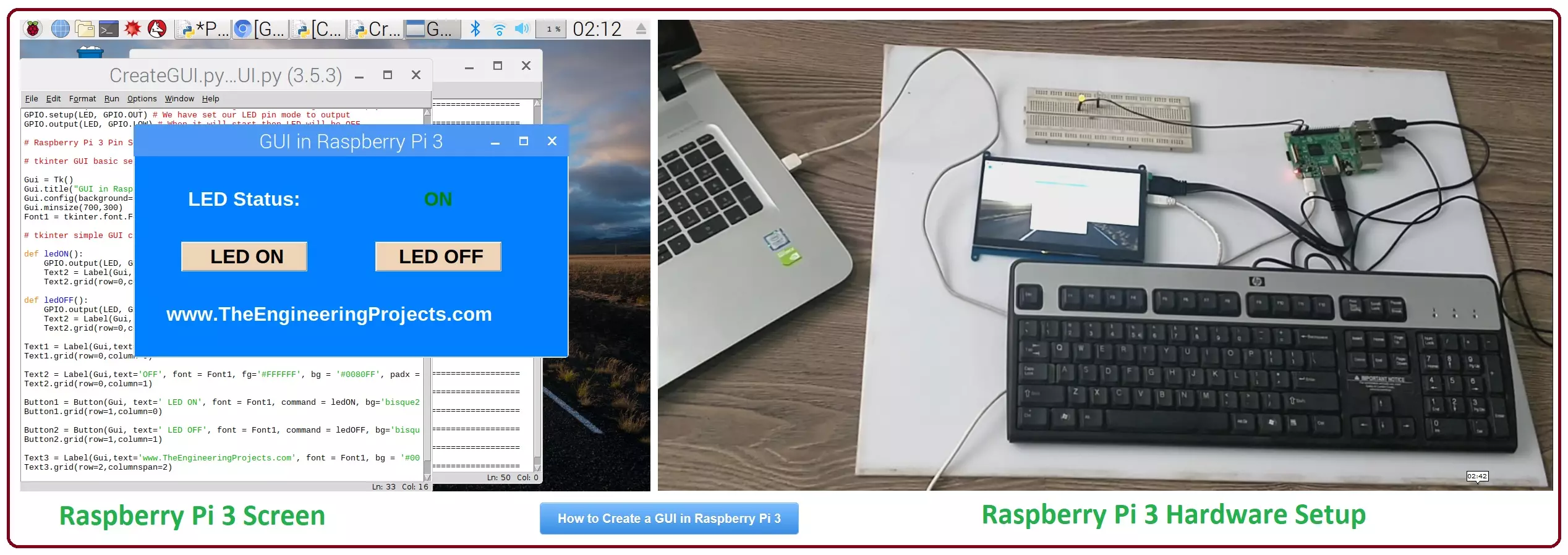
Hello friends, I hope you all are doing great. In today's tutorial, I am going to show you How to Create a GUI in Raspberry Pi 3. There are many different third party libraries available and the one I am going to use is tkinter. I have tried these libraries and I liked it the most so that's why I'm gonna use it in my future Raspberry Pi 3 Projects. In our previous tutorial on Raspberry Pi 3, we have had a look at LED Blinking using Raspberry Pi 3. So, today I am gonna work on the same project and we will add a GUI in it. GUI is an abbreviation of Graphical User Interface and it is used to give a presentable form to your project. We will add some buttons on our GUI and we will turn ON or OFF our LED using buttons. It's quite a basic tutorial but its essential to cover before working on bigger projects. So, let's get started with How to Create a GUI in Raspberry Pi 3:

How to Create a GUI in Raspberry Pi 3

  • I hope you have already Setup your HDMI LCD with Raspberry Pi 3, as we have done in our previous tutorials.
  • Here's an image of our final setup:
  • So open a new File in your Python IDLE and save it, I have given it a name CreateGUI.py
  • First of all we are gonna import our libraries in python, so here's the code:
# ************************************************************************** #
# ****                                                                  **** #
# *********** Code Designed by www.TheEngineeringProjects.com ************** #
# ****                                                                  **** #
# ****************** How to Create a GUI in Raspberry Pi 3 ***************** #
# ****                                                                  **** #
# ************************************************************************** #

# Importing Libraries

import RPi.GPIO as GPIO
import time
from tkinter import *
import tkinter.font

# Libraries Imported successfully
  • In the above code you can see, we have imported a new library which is tkinter library and we have also imported font from it.
  • Now we are gonna do some initial settings of our Raspberry Pi 3 LED Pin, as we have have done in LED Blinking using Raspberry Pi 3.
  • Here's the code for that:
# Raspberry Pi 3 Pin Settings

LED = 11 # pin11
GPIO.setwarnings(False)
GPIO.setmode(GPIO.BOARD) # We are accessing GPIOs according to their physical location
GPIO.setup(LED, GPIO.OUT) # We have set our LED pin mode to output
GPIO.output(LED, GPIO.LOW) # When it will start then LED will be OFF

# Raspberry Pi 3 Pin Settings

  • In the above code I have set all warnings to False as I think warnings are just annoying. :P
  • After that I have set our GPIO mode to Board because its lot easier to remember Pin Number as their number on board.
  • You can set this mode to BCM as well.
  • Next we have made our LED Pin output and have made it Low as I wanna keep my LED in OFF state when project starts up.
  • Now let's place some code for GUI initialization and basic settings,here's the code:
# tkinter GUI basic settings

Gui = Tk()
Gui.title("GUI in Raspberry Pi 3")
Gui.config(background= "#0080FF")
Gui.minsize(700,300)
Font1 = tkinter.font.Font(family = 'Helvetica', size = 24, weight = 'bold')

# tkinter simple GUI created

  • First of all, I have create an object named Gui, which is actually my GUI Board.
  • Then I have given it a title, which will appear as name of this GUI or software.
  • I have made the background light blue, it will look good.
  • the minimum size, I have set is 700 x 300, its in pixels (x, y).
  • Finally we have set our Font, which we are not using yet but will use in next section.
  • Now if you run your code then you will get something as shown in below figure:
  • You can see in above figure that we a got a simple board and the title is also there.
  • So, now let's add some Labels first on our GUI in pi 3:
Text1 = Label(Gui,text='LED Status:', font = Font1, fg='#FFFFFF', bg = '#0080FF', padx = 50, pady = 50)
Text1.grid(row=0,column=0)

Text2 = Label(Gui,text='OFF', font = Font1, fg='#FFFFFF', bg = '#0080FF', padx = 0)
Text2.grid(row=0,column=1)
  • I think these codes are self explanatory, I have added two texts "LED Status: " and "OFF".
  • I have given them the Font1 which we created in last section and then the background is again white, and I have also added some padding in x and y direction so that it won't touch the borders.
  • In this GUI tkinter coding we have grid system. The below image will clear the idea:
  • We have added both our Labels in first row, so here's the output of above code:
  • Now let's add two buttons below these Labels, which will control our LED and will turn it ON and OFF.
  • Here's the code for adding Buttons in GUI using tkinter:
Button1 = Button(Gui, text=' LED ON', font = Font1, command = ledON, bg='bisque2', height = 1, width = 10)
Button1.grid(row=1,column=0)

Button2 = Button(Gui, text=' LED OFF', font = Font1, command = ledOFF, bg='bisque2', height = 1, width = 10)
Button2.grid(row=1,column=1)
  • You have seen in above code that now these two buttons are in second row so they will come below these Labels.
  • The only thing worth mentioning here is the Command, its actually a function which will execute on pressing that button.
  • So, now we need to add these functions above Label codes.
  • Just try to understand the code rite now, I have shared the complete file below, which you can easily download.
  • So, here's these two functions' codes:
# Function for Buttons started here

def ledON():
    GPIO.output(LED, GPIO.HIGH) # led on
    Text2 = Label(Gui,text=' ON ', font = Font1, bg = '#0080FF', fg='green', padx = 0)
    Text2.grid(row=0,column=1)

def ledOFF():
    GPIO.output(LED, GPIO.LOW) # led off
    Text2 = Label(Gui,text='OFF', font = Font1, bg = '#0080FF', fg='red', padx = 0)
    Text2.grid(row=0,column=1)

# Function for Buttons ended here
  • In some cases you need to merge your columns or rows, for that you can use below code.
  • In below code, I have merged the columns of last row by using 'columnspan=2' and added our site's link.
  • It has merged the first two columns of last row and here's the code:
Text3 = Label(Gui,text='www.TheEngineeringProjects.com', font = Font1, bg = '#0080FF', fg='#FFFFFF', padx = 50, pady = 50)
Text3.grid(row=2,columnspan=2)
  • And finally we need to add our main loop code, which is like while(1) in python, it is given below:
Gui.mainloop()
  • Now run your code and you will get something as shown in below figure:
  • I have combined all the above codes and here's it's final form, it's now easy to understand:
# ************************************************************************** #
# ****                                                                  **** #
# *********** Code Designed by www.TheEngineeringProjects.com ************** #
# ****                                                                  **** #
# ****************** How to Create a GUI in Raspberry Pi 3 ***************** #
# ****                                                                  **** #
# ************************************************************************** #

# Importing Libraries

import RPi.GPIO as GPIO
import time
from tkinter import *
import tkinter.font

# Libraries Imported successfully

# Raspberry Pi 3 Pin Settings

LED = 11 # pin11
GPIO.setwarnings(False)
GPIO.setmode(GPIO.BOARD) # We are accessing GPIOs according to their physical location
GPIO.setup(LED, GPIO.OUT) # We have set our LED pin mode to output
GPIO.output(LED, GPIO.LOW) # When it will start then LED will be OFF

# Raspberry Pi 3 Pin Settings

# tkinter GUI basic settings

Gui = Tk()
Gui.title("GUI in Raspberry Pi 3")
Gui.config(background= "#0080FF")
Gui.minsize(700,300)
Font1 = tkinter.font.Font(family = 'Helvetica', size = 24, weight = 'bold')

# tkinter simple GUI created

# Funtion for Buttons started here

def ledON():
    GPIO.output(LED, GPIO.HIGH) # led on
    Text2 = Label(Gui,text=' ON ', font = Font1, bg = '#0080FF', fg='green', padx = 0)
    Text2.grid(row=0,column=1)

def ledOFF():
    GPIO.output(LED, GPIO.LOW) # led off
    Text2 = Label(Gui,text='OFF', font = Font1, bg = '#0080FF', fg='red', padx = 0)
    Text2.grid(row=0,column=1)

# Funtion for Buttons ended here

Text1 = Label(Gui,text='LED Status:', font = Font1, fg='#FFFFFF', bg = '#0080FF', padx = 50, pady = 50)
Text1.grid(row=0,column=0)

Text2 = Label(Gui,text='OFF', font = Font1, fg='#FFFFFF', bg = '#0080FF', padx = 0)
Text2.grid(row=0,column=1)

Button1 = Button(Gui, text=' LED ON', font = Font1, command = ledON, bg='bisque2', height = 1, width = 10)
Button1.grid(row=1,column=0)

Button2 = Button(Gui, text=' LED OFF', font = Font1, command = ledOFF, bg='bisque2', height = 1, width = 10)
Button2.grid(row=1,column=1)

Text3 = Label(Gui,text='www.TheEngineeringProjects.com', font = Font1, bg = '#0080FF', fg='#FFFFFF', padx = 50, pady = 50)
Text3.grid(row=2,columnspan=2)

Gui.mainloop()
  • If you got into any trouble then ask in comments.
  • Now when you click on the "LED ON" Button then your LED will turn ON and when you click on the "LED OFF" button, then your LED will go OFF.
  • LED status text on GUI will change from OFF to ON.
  • Both Raspberry Pi 3 Screen and its hardware setup are shown in below figure: (click & zoom)
  • Now when you click the LED OFF button then LED status will change from ON to OFF as shown in below figure:
  • I hope you have got the main idea of How to create GUI in Raspberry Pi 3.
  • In my coming tutorial, I will share many tutorials on raspberry Pi 3 in which we will create such simple GUIs and will display different sensors' values and will also control them.
  • You can download this CreateGUI.py file by clicking the below button:

[dt_default_button link="https://www.theengineeringprojects.com/RaspberryPi3/CreateGUI.rar" button_alignment="default" animation="fadeIn" size="medium" default_btn_bg_color="" bg_hover_color="" text_color="" text_hover_color="" icon="fa fa-chevron-circle-right" icon_align="left"]Download CreateGUI.py File[/dt_default_button]

So, that was all about How to Create GUI in Raspberry Pi 3. I hope you have got the detailed idea of GUI creation. In my coming tutorial, we will have a look at How to Control DC Motor with Raspberry Pi 3. Thanks for reading, have fun !!! :)
Syed Zain Nasir

I am Syed Zain Nasir, the founder of <a href=https://www.TheEngineeringProjects.com/>The Engineering Projects</a> (TEP). I am a programmer since 2009 before that I just search things, make small projects and now I am sharing my knowledge through this platform.I also work as a freelancer and did many projects related to programming and electrical circuitry. <a href=https://plus.google.com/+SyedZainNasir/>My Google Profile+</a>

Share
Published by
Syed Zain Nasir