


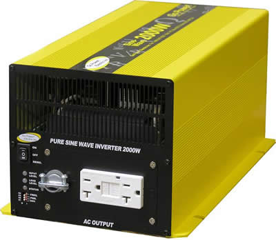
Basics of Inverters With Topology


| No. | Inverter tutorial series |
|---|---|
| 1 | Basics of Inverters with Topology |
| 2 | Major Components of Inverters |
| 3 | Pure Sine Wave Inverter Design with Code |
| 4 | Modified Sine Wave Inverter Design with Code |
Hello friends, I hope you are doing well. This is the first tutorial in our inverter series. We will begin with the purpose of an inverter, study the common output waveforms and then compare the power-stage topologies used to produce AC from a DC source.
An inverter looks simple in a block diagram, but a useful design must control voltage, frequency, waveform quality, current, temperature and fault energy at the same time. A circuit that produces an alternating voltage on an oscilloscope is not automatically a safe or well-regulated AC power source. Our goal here is to understand the engineering decisions before selecting components or writing control code.
What Is an Inverter?
An inverter is a power electronic converter that changes direct-current electrical power into alternating-current electrical power. The DC source may be a battery, photovoltaic array, fuel cell, rectified mains bus or another converter. The AC output may supply a stand-alone load, drive a motor or exchange power with an electrical grid through the required control and protection system.
The word inverter describes the conversion function, not one fixed circuit. A 12 V battery inverter that supplies 230 V, 50 Hz is one example. A variable-frequency motor drive that converts a DC link into three-phase AC is another. A solar string inverter may begin with hundreds of DC volts and feed a synchronized grid current without using a 50 Hz step-up transformer.
Basic Energy Flow
A practical stand-alone inverter normally contains several functional blocks:
- DC source and protection: battery or other source, fuse, reverse-polarity protection and disconnect.
- DC-link stage: direct battery bus, boost converter or isolated high-frequency DC-DC converter.
- Switching bridge: semiconductor switches arrange the DC-link voltage into positive, negative and sometimes zero output states.
- Output filter or transformer: reduces switching components, changes voltage and may provide isolation.
- Controller and gate drivers: generate timed switching commands and enforce dead time.
- Sensing and protection: measure voltage, current and temperature so faults can stop the converter safely.
No stage creates energy. If the load receives 500 W and the inverter is 90% efficient, the DC source must provide:
Pin = Pout / efficiency = 500 W / 0.90 = 555.6 W
From a nominal 12 V battery, the idealized input current is:
Iin = Pin / Vbattery = 555.6 W / 12 V = 46.3 A
The current rises further as battery voltage falls and may be much higher during a surge. This calculation explains why low-voltage inverters need short, thick conductors, low-resistance switches, secure terminals and a correctly placed DC fuse.
AC Voltage, Frequency and Power
For a sinusoidal voltage, the RMS value relates to its peak value as:
Vrms = Vpeak / √2
A 230 V RMS sine wave therefore has:
Vpeak = 230 V × √2 = 325.3 V
The inverter must also control output frequency, commonly 50 Hz or 60 Hz. Frequency and RMS voltage alone do not describe waveform quality. Harmonic content, short-term regulation, DC offset, crest factor and transient response all influence how a load behaves.
Loads are often rated in watts and volt-amperes:
Apparent power S = Vrms × Irms
Real power P = Vrms × Irms × power factor
A 230 V load drawing 2 A has 460 VA of apparent power. At a power factor of 0.7, it consumes about 322 W of real power. The inverter's semiconductors and conductors still carry the 2 A RMS current, so a watt rating alone may be insufficient for sizing.
Inverter Output Waveforms
Square-Wave Inverter
A bipolar square-wave inverter applies a positive DC level for one half-cycle and an equal negative level for the other. It is easy to generate and gives the full DC-link voltage to the load, but it contains strong odd harmonics.
For an ideal square wave with amplitude Vdc, the RMS value is Vdc. Its Fourier series contains the fundamental plus third, fifth, seventh and higher odd harmonics. The fundamental peak is:
V1,peak = 4Vdc / π
A meter may show the expected RMS value while a transformer, motor or audio device still runs hotter or noisier because RMS alone does not describe the harmonic spectrum.
Modified Sine-Wave Inverter
A modified sine wave, also called a modified square or quasi-square wave, inserts a zero-voltage interval between its positive and negative plateaus. Changing the plateau duration adjusts RMS voltage and some harmonic components.
If the waveform has magnitude Vpk for a total fraction D of each complete cycle and is zero for the remaining fraction, its ideal RMS value is:
Vrms = Vpk × √D
The waveform remains stepped and harmonic-rich. Simple heaters and some switch-mode supplies may accept it, while motors, transformers, timing circuits, audio equipment and appliances with waveform-sensitive controls may buzz, heat or malfunction. Compatibility must come from the equipment manufacturer rather than a blanket claim that nearly every load will work.
Pure Sine-Wave Inverter
A pure sine-wave inverter regulates its output to approximate a sinusoid with low total harmonic distortion. Modern designs commonly use sinusoidal pulse-width modulation, or SPWM, at a switching frequency well above the 50 Hz or 60 Hz fundamental. An LC filter attenuates the switching carrier and leaves the required low-frequency voltage.
The result is normally the best choice for general AC equipment, but the word pure is a marketing description rather than a complete test result. Check the specified THD, voltage regulation, surge capability, frequency tolerance and load conditions.
Multilevel and Resonant Inverters
A multilevel inverter synthesizes an output from more than two voltage levels. Neutral-point-clamped, flying-capacitor and cascaded H-bridge families can reduce device voltage stress, filter size or harmonic content at medium and high power, at the cost of more switches and more complex control.
A resonant inverter uses an inductive-capacitive network so switching occurs under favorable voltage or current conditions. It is common in induction heating, lighting and wireless-power applications. Its design centers on the resonant tank and load behavior rather than simply creating utility-frequency AC.
Waveform Comparison
| Waveform | Advantages | Limitations | Typical use |
|---|---|---|---|
| Square wave | Simple control and low switch count | High harmonic content and poor compatibility | Specialized simple loads |
| Modified sine wave | Simple and lower cost than filtered SPWM | Stepped output, audible noise and load restrictions | Cost-sensitive legacy systems |
| Filtered sine wave | Low distortion and broad load compatibility | Requires PWM, filter, feedback and careful layout | UPS, renewable energy and general AC loads |
| Multilevel | Lower step size and attractive high-voltage performance | More devices, sensing and control complexity | Solar, drives and medium-voltage conversion |
| Resonant | Can reduce switching loss in its design region | Behavior depends strongly on tank and load | Heating, lighting and specialized converters |
Half-Bridge and Full-Bridge Topologies
Half-Bridge
A single-phase half-bridge uses two controlled switches in series across a split DC link. The load connects between the switching midpoint and the DC-link midpoint. The topology uses fewer switches than a full bridge, but it requires a stable midpoint and produces half the full-bridge differential voltage for the same total bus.
Full H-Bridge
A full bridge uses four switches arranged in two legs, with the load between the leg midpoints. Turning on one diagonal pair applies positive bus voltage to the load; turning on the other diagonal pair reverses the voltage. Appropriate zero states support PWM and current freewheeling.
| Bridge state | Conducting commanded switches | Ideal load voltage |
|---|---|---|
| Positive | Upper switch of leg A and lower switch of leg B | +Vdc |
| Negative | Lower switch of leg A and upper switch of leg B | -Vdc |
| Zero | Both upper or both lower switches, when valid for the modulation and current path | 0 V |
The high-side and low-side switch in the same leg must never conduct together. That condition directly shorts the DC link and is called shoot-through. Gate-drive logic inserts dead time after one device turns off before its complement turns on. Too little dead time risks destructive cross-conduction; excessive dead time distorts the output and increases loss.
Texas Instruments describes the two-level H-bridge and its unipolar and bipolar switching options in its power topology report. A practical bridge also needs gate-driver undervoltage lockout, controlled turn-on and turn-off, current sensing and a hardware fault path that does not depend only on normal software execution.
Sinusoidal PWM and the Output Filter
In SPWM, the controller compares a sinusoidal reference with a high-frequency carrier or calculates equivalent timer duty cycles. The bridge produces voltage pulses whose average over each switching interval follows the sine reference. A feedback loop adjusts the modulation to regulate the output as the battery and load change.
For an ideal bipolar full bridge operating in the linear SPWM region, the fundamental output peak is approximately:
V1,peak ≈ ma × Vdc
Here ma is the amplitude modulation index. Exact usable range and gain depend on the modulation scheme, dead time, bus ripple and implementation.
An LC low-pass filter reduces the switching carrier. Its undamped resonant frequency is:
fc = 1 / (2π√(LC))
The filter cutoff must be comfortably above the 50 Hz or 60 Hz output and well below the PWM frequency, while still meeting load-transient and stability requirements. Selecting L and C from the equation alone is insufficient; inductor ripple current, saturation, capacitor RMS current, damping and the closed-loop response all matter.
TI's high-frequency inverter application report presents an isolated DC-DC stage followed by an SPWM full-bridge DC-AC stage, which illustrates how these blocks work together.
Low-Frequency Transformer Topology
The traditional low-voltage inverter switches the battery across the low-voltage winding of a 50 Hz or 60 Hz transformer. A center-tapped push-pull circuit may use two primary-side switches, while a full bridge can apply both polarities across a single winding.
The transformer steps the alternating primary voltage up to the required output and can provide galvanic isolation. The switching devices remain on the low-voltage side, but they carry high battery current. The transformer is large and heavy because its magnetic core operates at line frequency.
A transformer does not simply “step up the harmonic content.” It transfers frequency components according to its bandwidth, leakage inductance, magnetizing inductance and losses. The inverter switching waveform already contains harmonics. Flux imbalance or DC offset can saturate the core and cause very high current, so symmetrical volt-seconds and fast overcurrent protection are essential.
High-Frequency Two-Stage Topology
A high-frequency inverter commonly performs two conversions:
- An isolated push-pull or full-bridge DC-DC converter raises the battery voltage to a high-voltage DC bus.
- A high-voltage H-bridge uses SPWM to create the line-frequency AC output, followed by filtering.
Because the isolation transformer works at tens or hundreds of kilohertz rather than 50 Hz, it can be much smaller. The tradeoff is a more complex design with high-frequency magnetics, rectification, DC-link capacitors, isolated gate drive, electromagnetic-interference control and high-voltage switching.
For a 230 V RMS sine output, the peak is about 325 V. A non-isolated full bridge therefore needs a DC bus above the required peak after allowing for regulation and losses. That bus stores hazardous energy even when the original battery is only 12 V.
Other Important Topology Classifications
Voltage-Source and Current-Source Inverters
A voltage-source inverter is fed by a DC link that behaves mainly as a voltage source, normally supported by a large capacitor. A current-source inverter is fed by a DC link shaped as a current source, normally using substantial inductance. Their switching constraints and commutation paths differ, so a control rule suitable for one cannot automatically be applied to the other.
Single-Phase and Three-Phase Inverters
A single H-bridge creates a single-phase output. A standard three-phase voltage-source inverter uses three bridge legs. The controller produces phase references separated by 120 electrical degrees, often using sinusoidal PWM or space-vector modulation.
Stand-Alone and Grid-Connected Inverters
A stand-alone voltage-source inverter establishes output voltage and frequency for its local load. A grid-connected inverter synchronizes with an existing grid and regulates injected current. Grid connection requires certified anti-islanding, protection, filtering and compliance with local interconnection standards. It is not safe to connect a homemade stand-alone inverter to utility wiring.
Efficiency and Losses
Inverter efficiency is:
Efficiency = Pout / Pin × 100%
The main losses include:
- Switch conduction loss, approximately related to
I²RDS(on)for MOSFETs. - Switching loss while voltage and current overlap during transitions.
- Gate-drive and control-circuit power.
- Transformer copper and core loss.
- Inductor copper and core loss.
- Capacitor ESR loss and rectifier loss.
- Idle consumption when little or no load power is delivered.
Efficiency varies with load, battery voltage, temperature and operating mode. A single peak-efficiency number does not describe light-load behavior or thermal performance at rated power.
Protection Required in a Practical Inverter
| Protection | Purpose |
|---|---|
| Input fuse and disconnect | Limits energy during a wiring or semiconductor fault |
| Reverse-polarity protection | Protects against incorrect battery connection |
| Undervoltage cutoff | Prevents excessive battery discharge and unstable control |
| Overvoltage protection | Protects the DC link and load during regulation faults |
| Cycle-by-cycle current limit | Stops damaging switch current quickly |
| Short-circuit shutdown | Handles sustained output faults |
| Overtemperature shutdown | Protects switches, magnetics and enclosure |
| Gate-driver undervoltage lockout | Prevents partially enhanced power switches |
| Output residual-current and earth protection | Supports shock protection where required by system design and standards |
Protection must respond at the timescale of the fault. A microcontroller may regulate normal voltage, while a comparator and gate-driver shutdown path handle a switch current that can become destructive within microseconds.
How to Choose an Inverter Topology
- Define DC input range, AC voltage, frequency, continuous VA, real power and surge duration.
- Describe load power factor, starting current, nonlinear current and allowable waveform distortion.
- Decide whether galvanic isolation is required and identify the governing safety standard.
- Choose line-frequency transformation, high-frequency isolation or a non-isolated high-voltage bus.
- Select bridge devices and switching frequency from voltage, current, loss and thermal calculations.
- Design modulation, dead time, sensing, feedback and the output filter as one control system.
- Add fault protection, safe discharge, fusing, creepage, clearance, earthing and enclosure provisions.
- Verify with current-limited low-voltage tests before increasing energy or voltage.
Safety Note
An inverter capable of producing 120 V or 230 V AC can cause fatal electric shock and fire. Its DC bus capacitors may remain charged after the battery is removed. High battery current can also melt conductors or start a fire without producing a hazardous AC voltage. Work on high-power hardware requires appropriate training, isolation, protective equipment, enclosed test methods and properly rated instruments.
Do not connect an experimental inverter to household wiring or the utility grid. Grid-connected equipment requires certified protection and approval under the rules of the installation location.
Practical Review
An inverter controls semiconductor switches so a DC source produces an alternating output. A square or modified waveform can be generated with simple line-frequency switching, while a low-distortion sine output normally uses PWM, feedback and filtering. The H-bridge is the central single-phase power stage, but it may operate directly from a low-voltage transformer winding or from a boosted high-voltage DC link.
The topology follows the requirements. Input voltage, isolation, output waveform, power, surge, efficiency, weight, cost and safety determine whether a low-frequency transformer, high-frequency two-stage converter, multilevel structure or another approach is appropriate.
Frequently Asked Questions
Does every 12 V to 230 V inverter first produce 12 V AC?
No. A low-frequency transformer design may switch 12 V across a transformer primary. A high-frequency design first produces a high-voltage DC bus and then creates 230 V AC with a high-voltage bridge.
Why is a 500 W inverter input current so high at 12 V?
Power is voltage multiplied by current. Delivering hundreds of watts from a low voltage requires tens of amperes, and conversion loss increases the required battery power further.
Is modified sine wave safe for every appliance?
No. Compatibility depends on the appliance input circuit and the inverter waveform. Motors, transformers, audio equipment and timing or control circuits may run hotter, noisier or incorrectly. Follow the equipment manufacturer's power-source requirements.
What is shoot-through?
Shoot-through occurs when the high-side and low-side switches in one bridge leg conduct together, shorting the DC link. Correct gate-drive interlocking, dead time and fault handling are essential.
What does total harmonic distortion measure?
Voltage THD compares the RMS contribution of harmonic components with the RMS fundamental component. Lower THD generally means a waveform closer to a sine wave, but regulation, transient behavior and load compatibility still need separate evaluation.
Does a transformer remove all inverter harmonics?
No. A transformer transfers components within its frequency response and introduces its own leakage, magnetizing and loss behavior. Filtering and modulation determine waveform quality; the transformer is not a universal harmonic remover.
Why use a high-frequency topology?
Operating the isolation transformer at high frequency can reduce its size and weight. The design becomes more complex and must control additional switching loss, electromagnetic interference and a hazardous high-voltage DC link.
Can I connect a home-built inverter to the grid?
No. Grid connection requires synchronized current control, anti-islanding, protection, certified hardware and authorization under local interconnection rules. A stand-alone inverter is not a grid-tie inverter.
In the next article, we will use this foundation to study the major components of an inverter and the role each one plays in the complete power-conversion system.

Hi syed,
Can you tell me any other IC to produce the square wave, because CD4047 has a constant 50% duty cycle, want a variable duty cycle..
@avitronics Bro there are many ICs which are used for square wave generation like LM339 . You can also generate it using 555 a little assembly is required along with it ....
do you know about single phase cascaded multilevel inverter with reduced number of power switches. what is that?
1 reply
Hi,
Yeah its also an inverter topology, I once designed it in MATLAB. Search it on Google, I think you will find a lot of stuff on it.
Thanks.
how to build an inverter device
would u suggest me steps in building inverter using the "second method" that you have mentioned above?
1 reply
Yeah sure add me on skype and we can discuss it in detail. Thanks.
Sir I am going to make a 12v DC to 220v Ac invertor.Can u please send me steps along with circuit?
how to implement codes for 11 level multi Inverter in MATLAB??
1 reply
Hi,
Add me on Skype and we will discuss it in full detail. My Skype id is theenggprojects.
Thanks.
sir plz upload pure sine wave inverters using pic microcontrollers
hello there,
can you help with determination of ratings of components to be used in the design and how the net output power can be determined.
Comments
13