Today, I'll unlock the details on How to Create a Jet Fighter Model In AutoCAD. The drawings were published on the Internet * and represent several types...
Hey Guys! Hope you are doing well. Today, I'll unlock the details on How to Create a Jet Fighter Model In AutoCAD.
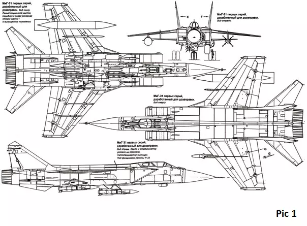
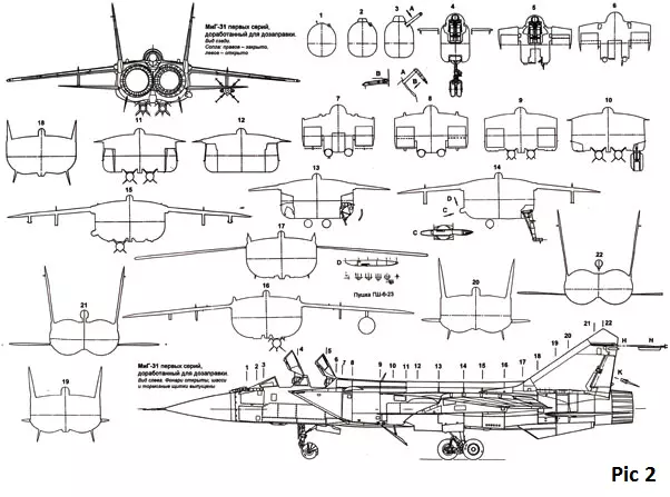
The drawings were published on the Internet * and represent several types, 22 cross sections (fuselage forming elements) perpendicular to the longitudinal axis of the fuselage, and a number of additional sections (Figures 1 and 2).
The accuracy of the drawings, of course, is not high, because these are just data for the modelers. We will have to believe this data, take them for truth in the first instance and start creating a digital prototype.
How to Create a Jet Fighter Model in AutoCAD
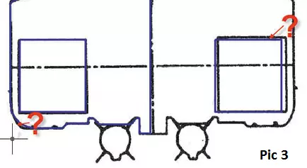
Where to begin? From converting JPEG to DWG (to increase their self-esteem, this tedious process can be called manual vectorization of vector graphics). One of the stages of work is shown in the pic. 3. Question marks indicate that the decision to choose the accuracy remains for the author of the model creation. Pic. 4 shows how the orthogonal sections and the top view look, the visual style of the 2D framework.
Some sections are not shown, so as not to frighten the unsophisticated reader with the apparent complexity of the proposed construction. Nevertheless, this part of the work should be done very carefully, repeatedly checking all the dimensions, because what will be laid now, we get at the output.
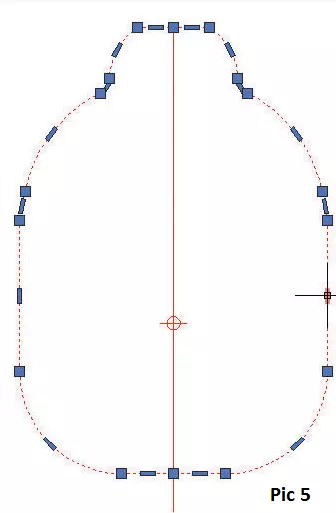
Each of the sections is a closed polyline (pic 5). The pic shows that the new version of AutoCAD 2011 has new handles for editing the polyline. I want to say many thanks to the developers for this tool. When solving such problems, using pens and a convenient context menu saves a lot of time.
Creating 3D geometry
Of course, it is tempting to apply the method of lofting to all sections - from the tail to the cut of the nozzle. The most important thing is that the system will helpfully do it.
The 3D body created as a result of this procedure will be very complex and beautiful, it can be used to create alien ships in fantastic cartoons, but to our task, this, alas, will not work.
Therefore, it is necessary to break the fuselage into several structural parts: the nose, the bow with the cockpit, the middle part, the tail part, the nozzles. Wings, horizontal plumage, and keels were modeled separately. Pic. 6 shows the results of one of the stages of work.
It is worth paying attention to the following innovation of AutoCAD 2011 - when creating a body or surface by the method of lofting, you can change the law of lofting after creating a body (surface).
In previous versions of this possibility was not, and to predict the result with a complex geometry of the cross sections is often quite difficult. Pic. 7 shows the highlighted 3D created by the method of lofting, and a drop-down menu, the points of which allow us to choose the law of changing the loft for an already constructed body.
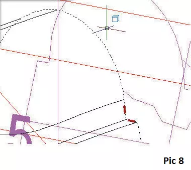
Another new feature of AutoCAD 2011 is the improved choice of sub-objects. To create the next section of the fuselage, the first section is the last section of the previous section. You can select this section by holding down the Ctrl key while selecting the subobject selection (pic 8).
We transform the primitives from which the section is made into a polyline or region (depending on the task), and we continue to create the next section of the fuselage. In previous versions of the system, you had to use the Extract Ribs command, and then long to clean the drawing from the heap of fragments formed - arcs, segments, splines.
The Quick Selection command had to be applied repeatedly, so this procedure was by no means fast. However, even more, effective work to create complex geometry is provided for the first time in AutoCAD 2011 new objects - NURBS surfaces. What do NURBS surfaces "know"? Here is not the most complete list:
create a very complex geometry of objects, while they obey the laws of Boolean algebra (union, intersection, subtraction);
create transitions between surfaces;
Create transitions between 3D objects using surfaces;
close the surface and create a 3D body;
cut one surface of the other;
edit control vertices;
assign materials to surfaces;
convert surfaces to 3D and vice versa (with the geometric possibility of this operation).
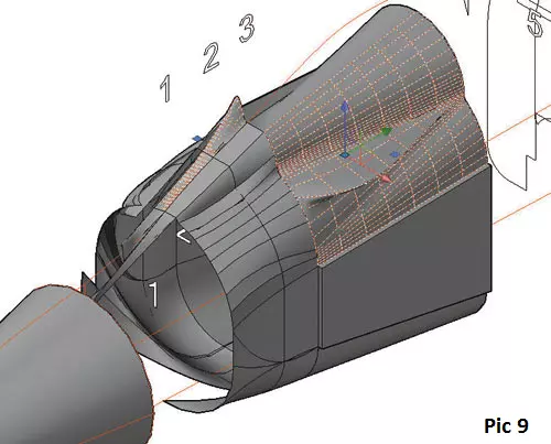
Pic. 9 illustrates the work with surfaces when creating the nose of the fuselage.
A quite legitimate question may arise: where are the surfaces, because until now we modeled the aircraft with 3D bodies? The answer is simple: this site was too complicated for solid modeling and we turned it into a surface.
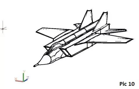
Wings, horizontal tail, and keels were modeled again by the method of lofting. The exact wing profiles in the initial data did not appear, so in all cases, a conditional, so-called chest-shaped profile, characteristic of supersonic flow was created. Nasal endings of profiles, arcs of small diameter. The nozzles are simple enough to model with surfaces. Pic 10 and 11 are almost complete work - together with the result they demonstrate another new feature of AutoCAD 2011 - visual styles. Pic. 10 shows the Sketch style, Pic. 11 - Tinted with edges.
The multicolor in Pic. 11 are temporary layers created in order to better distinguish the desired objects. By the way, about the layers. Finally, the seemingly eternal system error, the problem of the letter "b" in the name of the layer, was eliminated. Now, this is a story, with which I congratulate all users of AutoCAD!
Creating a cockpit
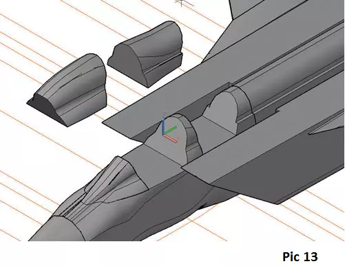
This is one of the most difficult stages in modeling. Its complexity lies in the fact that it is necessary to cut the model created by planes tilted at very intricate angles, then use logical operations to recreate the rest of the model. Pic. 13 shows the result of this procedure.
It remains to convert the necessary parts to the surface and assign a transparent material, but this is the next stage of the work - visualization.
Visualization
In AutoCAD 2011 there are quite a lot of new features, including a material browser containing thousands of professionally produced materials.
This browser is unified, that is, it is exactly the same as in programs 3ds max, AutoCAD Inventor, and AutoCAD Revit. Of course, there was the opportunity to create your own materials from the template and from scratch. In order not to do this, we assign the material to the fuselage aluminum, the lantern to the glass, and the LDPE tube to the chrome steel.
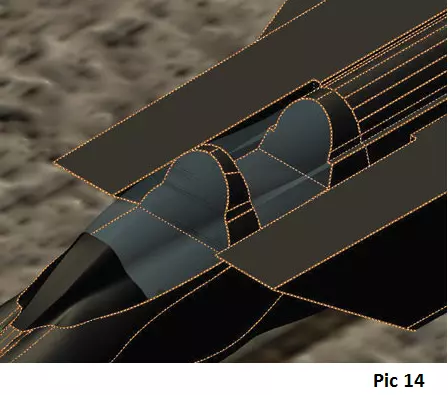
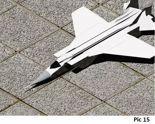
Pic. 14 shows the assignment of materials to the lantern, Pic. 15 - the resulting picture as a whole. Pic. 16 - one of the options for visualization (render) in sunlight.
Conclusion
This article demonstrates the possibility of creating a model aircraft in AutoCAD 2011. Why do it? What to do about it?
Calculation of distributed characteristics by the finite element method (FEM)
Get rid of the materials. Using the Unification command, we create a single 3D object, which we immediately turn into a surface.
With the help of the available tools, we change the number of partitioning panels, we match the boundaries and send them to the corresponding calculation program.
Calculation of dynamic characteristics, a creation of the model for wind tunnel
Get rid of the materials. Using the Unify command, we create a single 3D object.
We extract the data. Insert the average density, calculate the integral dynamic coefficients.
To make a model for purging in a wind tunnel using standard tools AutoCAD we will create project documentation and transfer it to production.
That's all for today. I hope you have got a clear idea about creating jet fighter model in AutoCAD. If you are unsure or have any question, you can approach in the comment section below. I'd love to help you in any way I can. Thanks for reading the article.
syedzainnasir
I am Syed Zain Nasir, the founder of The Engineering Projects (TEP). I am a
programmer since 2009 before that I just search things, make small projects and now I am sharing my
knowledge through this platform. I also work as a freelancer and did many projects related to
programming and electrical circuitry. My Google Profile+Follow
Get Connected
Comments on ‘’ How to Create a Jet Fighter Model in AutoCAD ‘’ ( 1 )
0
Says:
I really liked how you explained how to create a jet fighter model in Autocad with help of pics.
thanks for sharing such a enlightening info.
Reply