


Introduction to ACS712


Introduction to ACS712
- ACS712 is a current sensor, which can detect AC or DC current easily. The maximum values of AC or DC which can be detected is 30A. Its operating voltage is 5v.
- ACS712 is available in small surface mount SOIC8 package. Its lead-frame is plated with 100% matte tin, which is compatible with standard lead-free printed circuit board assembly process.
- Its package allows easy implementation by the customer, its typical applications are motor control, load detection and overcurrent fault protection.
- It consists of a precise linear hall circuit with a copper conduction path located near the surface of the die. When applied current passes through this copper conduction path generates a magnetic field which is sensed by Hall integrated circuit (IC) and converted into a proportional voltage.
- An output of ACS712 has a positive slope (>VIOUT (Q)) when increasing current passes through a primary copper conduction path (from pin 1 and 2, or pin 3 and 4), which is the path used for current sensing. The internal resistance of this conductive path is 1.2 mO. The thickness of the conductor provides survival for a device during the over-current condition.

ACS712 Pinout & Description
- There is three main pinout of ACS712, which are described below with detail description.
| Pin# | Type | Parameters |
| Pin#1 | Vcc | This is an input supply pin. 5v is given on this pin. |
| Pin#2 | Output | This is output analog voltage proportional to current. |
| Pin#3 | Ground | This is used for ground. |
- For better understanding let's see ACS712 pinout diagram.

- Now, we discuss ACS712 features.
Features of ACS712
-
- These are the main features of ACS712.
- It measures both DC and AC current.
- Its operating voltage is 5v.
- It is available in 5A, 20A and 30A module.
- It provides isolation from the load.
- It is easily integrated with MCU.
- It provides a low noise analog signal path.
- Its bandwidth is 50 kHz.
- It is available in low profile SOIC8 package.
- Its total error is 1.5% at TA = 25°C and 4% at –40°C to 85°C.
- Its output sensitivity is 66 to 185 mV/A.
- Its output voltage are proportional to AC or DC currents.
- It has an extremely stable output offset voltage.
- Its magnetic hysteresis is nearly zero.
- These are the main features of ACS712.
ACS712 Arduino Interfacing
- It is very easy to interface ACS712 with a microcontroller, you should also have a look at ACS712 Arduino Interfacing for better understanding.
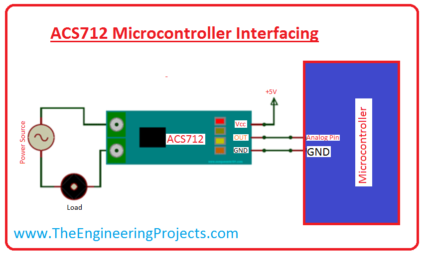
- In the given circuit diagram, the ACS712 module has two Phoenix terminal connectors with mounting screws as shown in the circuit diagram in green color. At these terminals, wires are connected.
- In our circuit diagram we are measuring current drawn by the motor, so the wires which are connected with motor is passed through the ACS712 module. Make sure ACS712 module is connected in series with the motor.
- On the other side of the module, we have three pins, Vcc is connected with +5V power supply and ground is connected to the ground of MCU.
- Analog voltage given by the ACS712 module can be read using an analog pin of Microcontroller.
- You can interface ACS712 with almost every microcontroller i.e. Arduino, PIC Microcontroller, 8051 etc.
- For a better understanding of this module, let's see the circuit diagram.

Applications of ACS712
- These are some applications of ACS712.
- It is used for motor speed control.
- It is used for load detection and management.
- It is used as switched-mode power supplies.
- It is used for over current fault protection.
×
![]()


