Introduction to TIP125


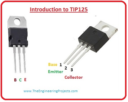
Introduction to TIP125
- It is a bipolar PNP transistor, which is created for swapping and intensification submissions. It is the corresponding of transistor TIP121.
- These transistors are produced in planar expertise with base isle design and monolithic Darlington pair formation.
- This transistor can work for the load of sixty volts having a maximum current of eight amperes incessant current of five amperes.
- Which makes it appropriate for intermediates and higher power electronics circuitries such as motor control or larger power consuming power light-emitting diodes.
- It is ordinarily used for such loading devices which consume high current and for such application where higher intensification is needed.
- As it has less value of VBE which is five volts so it can be easily regulated by a microcontroller.
- If you are searching for such components which can effortlessly be monitored by logical instruments like microcontrollers and can be used for higher loading devices or for higher intensification then it will be the right component for you.
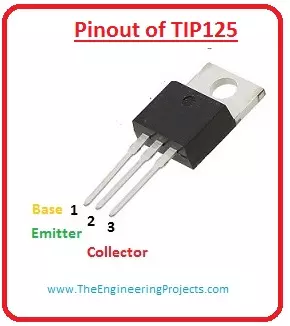
Pinout of TIP125
- These are the main pinout of TIP125.
Let's see a diagram of the pinout.Pin# Type Parameters Pin#1 Emitter It is typically related to the ground terminal. Pin#2 Base It used to turn on or off the transistor. We can say it mechanism like a switch. Pin#3 Collector This terminal of the transistor is linked with the load. 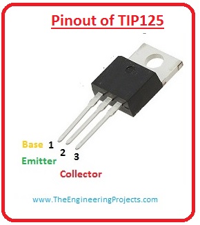
Features of TIP125
- It is an intermediate power using a Darlington pair transistor.
- It provides a higher value of direct current gain of nearly a thousand.
- Its collector current is five amperes.
- The voltage at its collector and emitter terminal Vce sixty volts.
- The voltage at its collector and base is sixty volts.
- Its voltage at emitter and base terminals is five volts.
- Its base takes a current of 120 milliamperes.
- Its maximum loading current is eight ampers.
- It offered in To-220 casing.
Ratings of TIP125
| Symbols | Ratings | Parameters |
| VCEO | 60 V | These are the voltage across collector and emitter. |
| VCBO | 60 V | These are the voltage around the collector and base. |
| VEBO | 5 V | These are the voltage around emitter and base. |
| IC | 5 A | It is the current at collector which is dc. |
| IB | 120 mA | It is the current at the base. |
| PD | 65 A | It is the total power dissipated by the transistor. |
| Tstg | -65 C to 150 C | It is the Junction Temperature. |
| TJ | -65 C to 150 C | It is the Junction Temperature. |
Electrical Charestrastic of TIP125
| Symbols | Ratings | Parameters |
| VCEO | 60 V | These are the collector and emitter sustaining voltage. |
| ICEO | 0.5 mA | It is the collector cut-off current. |
| ICBO | 0.2 mA | It is the value of collector cut off the current. |
| IEBO | 2 A | This is the emitter cut off the current. |
| hFE | 1000 | This is the value of gain. |
| VCE | 2 V | These are the collector and emitter saturation voltages. |
| VBE | 2.5 V | It is the base-emitter operating voltage. |
| Cbo | 300 pF | It is the output capacitance. |
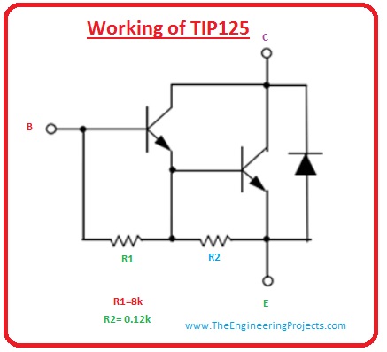
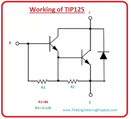
Working of TIP125
- We have discussed earlier that TIP125 is Darlington pair transistor. Its functioning is similar to a PNP transistor.
- As this transistor has Darlington paint in it due to this it has good collector current rating near five amperes.
- The Darlington circuitry of this transistor is given in the figure. In this circuit, we can see that in this casing there are a two-transistor.
- The emitter (E) of one transistor is linked with the base terminal of 2nd and collector of both are linked with each other to create Darlington pair.
- This assembly enhances the gain and current rating of the transistor.
Applications of TIP125
- These are some applications of tip125.
- It can be used for switching of higher current consuming up to the 5 ampers loading devices.
- It works as an intermediate power-consuming switching.
- it is used for such circuits where higher amplification is required.
- It used to control motors speed.
- It used for rectification process.
×
![]()