


Resistors in Series Combination


Resistors in Series Combination
- The circuitry that has a connection of the resistances in a single line is called a series resistance circuit.
- In this method of the resistance connections, the value of current remains the same across every resistance.
- You can see in the given diagram, the current across each resistance will be the same.
IR1= IR2 =IR3 = 1mA
- In this given circuitry there are 3 resistances are connected in series, that is R1, R2, R3.
- As the circuitry has a series combination of the resistance so, to get total resistance of the circuitry we will add all these 3 resistances.
Rt = R1 +R2 +R3
- If we put values of these resistances in the above-given equation we will get the equivalent resistance of the circuitry.
Req = 2O + 3O + 5O =10O
- So the equivalent resistance of the circuitry will be ten ohms, it can also be defined as the resistor that can be added in place of all resistances in circuitry is known as the equivalent resistance of the circuitry.
- The final expression to find the net resistance of the circuitry is given as.
Rt = Rx + Ry + Rz + ….. Rn
The voltage of the Series Resistors
- In above-given circuitry, we can see that the value of the voltage across every resistance is different from others. It is because the voltage drop across each resistor is different due to the difference value of the resistances.
- We can find the total voltage at the terminals A and of the circuitry by the given formula.
Vt = VR1 + VR2 + VR3 = 10V
- If we apply Ohm's Law to every resistance we can find the value of the voltage across each resistance.
VR1= I x R1= 1A x 2O = 2V
VR2 =I x R2 = 1A x 3O = 3V
VR3= I x R3 = 1A x 5O = 5V
- If we add thses voltage we get the ten volts that are equals to the applied voltage to the circuitry.
- So, we can conclude that the total voltage of the series circuitry is equal to the sum of the voltages across every circuitry.
Vt= VRx + VRy +VRz+........+ VRn
The Voltage Divider Circuit
- In the given diagram, you can see the circuitry that has 2 resistance Rx and Ry, connected in a series.
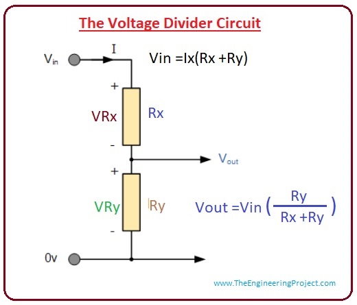
- The input voltage is provided at the resistance Rx and the output is taken from the resistance Ry.
- The value of the output voltage can be found by the voltage divider formula that is given below.

Vout = Vin (Ry)/(Rx+Ry)
- Now solve such circuitry that has the more than 2 resistances, in given circuitry you can see there is 4 resistor and their values are also mentioned.
- We now apply the voltage divider formula to find the value of voltage across every resistance.
Vab = VR3= Vs x (R3/R1+R2 +R3+R4)
= 10 x (30)/ (10+20+30+40)
Vab = 3V

Applications of Resistors in Series
- To see the practical application of the series resistaces we construct an circuitry and solve it.
- You can see the circuitry in the figure that is similar to the circuitry that we discussed in the voltage divider circuit, but in this circuity, there is a light-dependent resistance, it will convert any physical quantity into the electrical signal.
- Let's suppose that the value of the LDR is ten-kilo ohm and resistor RX value is a thousand ohms if we apply the voltage divider rule than we have.
Vout = Rx/(Rx +Ry) x Vin
=1000/(10000 +1000) x 12
Vout =1.09

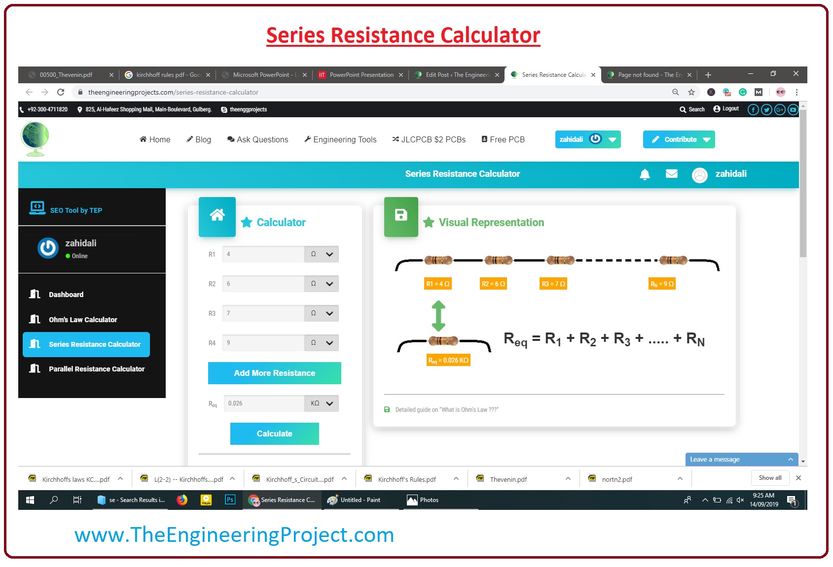
Series Resistance Calculator
- As we discussed earlier our online Series Resistance Calculator now we explain how it works practically.
- In the given figure, you can see the practical representation of the calculator.
- There are two portions of this calculator first is value box where you put values of your circuitry resistance these value can be in ohm, kilo-ohm, mega-ohm, according to your requirements.
- In other portion, there is circuitry that will show the practical implementation of your circuitries.
- In given figure I added four different values of the resistances in the value box, you can add any no of resistances by Add More Resistance Button, and the equivalent resistance of the 4 resistance is shown in Req box.
- The circuitry of the four resistances is shown on the right side in the figure.

×
![]()


