Introduction to TIP42


Introduction to TIP42
-
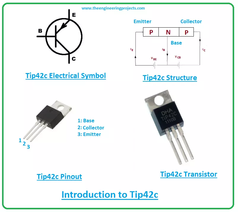
- Tip42 is an epitaxial medium power silicon transistor mainly used for switching and amplification purpose. It falls under the category of PNP transistor and comes with current gain ranging from 15 to 75.
- This current gain demonstrates the capacity of transistor it can amplify the current. It’s a ratio between the output current and input current.
- Tip42 is a bipolar transistor which means two charge carriers are used in the conductivity process inside the transistor.
- Both electrons and holes take part in the conductivity process. And in this case of PNP transistor, holes are majority carriers. And electrons are minority carriers in the case of NPN transistors.
- This PNP transistor contains three terminals called the emitter, base, and collector. All these terminals carry different functionality and different doping concentration.
- This different doping concentration is the main reason this bipolar transistor is not symmetrical. The external circuit is connected with the transistor through these terminals.
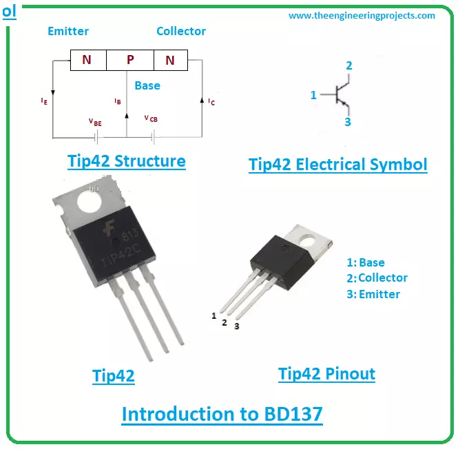
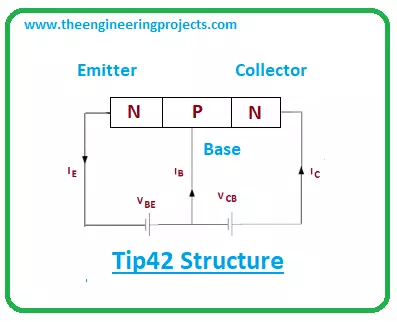
- Tip42 is composed of two p-doped layers and one n-doped layer. The n-doped layer is sandwiched between the two p-doped layers. The two p-layers represent the collector and emitter terminals and the n-layer represents the base terminal. The N sign shows, a negative voltage is applied on the base terminal to trigger and start the transistor action.
- This bipolar transistor controls the small input current and produces the large output current, the reason these devices are called current-controlled devices because two charge carriers are used for conductivity in contrast to FETs(field effect transistor) which is unipolar voltage-controlled devices. Where conductivity is carried out with only one charge carrier.
TIP42 Features
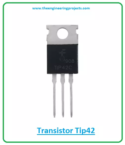
The following are the main features of transistor BC538.- Package: TO-220
- Material: Silicon
- Type – PNP
- Emitter-Base Voltage: 5 V
- Collector-Base Voltage: 40 V
- Collector-Emitter Voltage: 40 V
- Collector Dissipation: 65 W
- Collector Current: 6 A
- Transition Frequency: 3 MHz
- Current Gain (hfe): 15 to 75
- Storage Junction Temperature: -65 to +150 °C
- Plus, make sure your ratings don’t exceed these absolute maximum ratings while you’re working with the device, otherwise they will badly damage the device and thus the entire project.
- Both collector-emitter and collector-base voltages are 40V while the emitter-base voltage is 5V which projects you need to apply 5V to initiate the transistor action.
- The Collector current is 6V which indicates this transistor can support load under 6A. The transition frequency is 3MHz and power dissipation is 65W which is the amount of energy released during the working of this transistor.
- DC common-emitter current gain ranges from 15 to 75. It is a ratio between collector current and base current. This describes the capacity of transistors it can amplify the current. This is a relation between output amplified current to input small current.
- Another important current gain is the common-base current gain which is a ratio between collector current and emitter current and its value is always less than one. Normally ranges from 0.5 to 0.95.
- The small current at one pair of terminals is used to produce large current across other pairs of terminals of the transistor and this process is used for amplification purposes.
- It is important to note that the PNP transistors are less likely to employ for amplification purposes than NPN transistors. Because the mobility of electrons in the NPN transistor is far better and quicker than the mobility of holes in PNP transistors.
TIP42 Pinout
The Tip42 consists of three main terminals called: 1: Base 2: Collector 3: Emitter The following figure shows the pinout diagram of Tip42.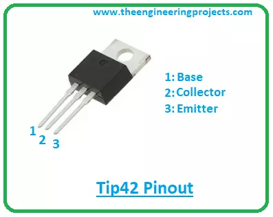
- The collector terminal is lightly doped and the emitter terminal is highly doped in contrast to the other two terminals.
- The collector terminal is 10-times lightly doped than the base terminal. And this transistor is manufactured in such a way, the collector side covers the entire emitter terminal area.
- The base terminal is responsible for the entire transistor action.
- This base terminal acts like a control valve that controls the number of holes in the case of the PNP transistor and the number of electrons in the case of NPN transistor.
- When 5V is applied at the base terminal, it gets biased and starts the transistor action where current moves from emitter to collector terminal which is the opposite in the case of NPN transistors where current moves from collector to emitter terminal. And in both cases base terminal controls the amount of current passing through it.
TIP42 Datasheet
Before you apply this device into your project, scan through the datasheet of the component that helps you get a hold of the main characteristics of the device. You can download the datasheet of Tip42 by clicking the link below.TIP42 Applications
Tip42 is used in the following applications.- Used for switching and amplification purpose.
- Used to drive load under 6A.
- Incorporated in the motor control circuit
- Employed in H-bridge circuit
- Incorporated in the voltage regulator circuit
×
![]()