1n4734 Zener Diode Datasheet, Pinout, Features & Applications


Hi Folks! I hope you’re well today. I welcome you on board. In this post today, I’ll walk you through the Introduction to 1n4734.
The 1n4734 is a silicon planner power Zener diode that is employed as a low current voltage regulator. It is incorporated as a shunt regulator in many applications. This Zener diode conducts the current in both directions in contrast to the regular diode that conducts in one direction only i.e. regular diode conducts in forward biased condition only. This Zener diode conducts in both conditions forward biased condition and reverse biased condition. Power dissipation in this Zener diode is 1W and standard Zener voltage tolerance is ±10%.
I suggest you read this entire post till the end, as I’ll detail the complete Introduction to 1n4734 covering datasheet, pinout, main features, and applications. Let’s dive in.
Introduction to 1N4734
- The 1n4734 is a Zener diode employed as a low-current voltage regulator. It is also employed in clipping circuits with high power ratings. This Zener diode is made of semiconductors and is used in voltage protection circuits.
- The current flows from the anode side to the cathode side in the regular diode in a forward-biased condition. On the other hand, in the case of the Zener diode, current conducts in both conditions i.e. forward biased condition and reverse biased condition. Forcing regular diodes to conduct in both conditions will damage the device.
- The Zener diode is normally used in modern electronics and is constructed by plenty of different voltages.
- While picking the Zener diode there are two parameters that you should consider… one is the power dissipation and the other is the power Zener voltage. When a higher reverse voltage is applied to the Zener device it creates the Zener voltage.
- Some Zener diodes experience sharp and highly doped p-n junction when they undergo a Zener effect or Clarence Zener.
- The power dissipation inside the Zener diode is used to identify the amount of current flow. More power dissipation results in more current flow. Power dissipation in this Zener diode is 1W.
- Zener diodes are utilized to generate low-power supply rails using higher voltages. Reference voltages in the electrical circuits are also produced by these Zener diodes.
- In some electrical circuits, there is a limit to the applied voltage. The voltage applied above this limit can damage the device. These Zener diodes are used in those circuits to prevent circuits from overvoltage.
1N4734 Datasheet
Before you apply this component to your project, it’s wise to have a look at the datasheet of the component that contains the main characteristics of the device. Click the link below if you want to download the datasheet of 1n4734.1N4734 Pinout
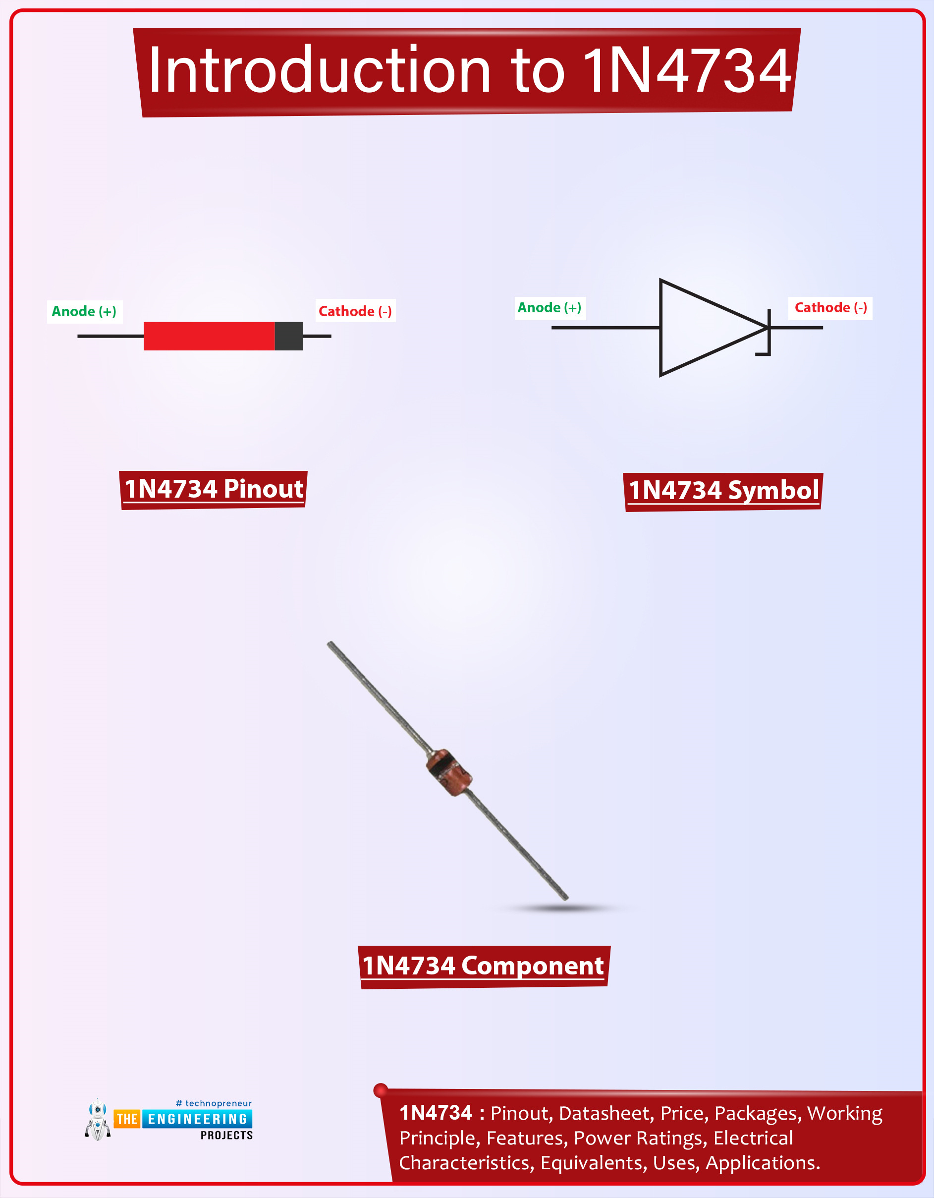
The following figure shows the pinout diagram of 1n4734.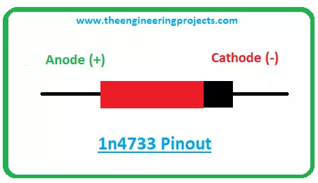
- The 1n4734 comes with two terminals named anode and cathode. The anode terminal is positive while the cathode terminal is negative.
- The current enters the diode through the positive anode terminal while the current leaves the diode through the negative cathode terminal.
- The current flows in both conditions in 1n4734 i.e. forward biased condition and reverse biased condition.
1N4734 Features
The following are the main features of the 1n4734 Zener diode.- Package = DO-41
- Zener Voltage (VZ) = 5.1V
- Used as shunt regulators.
- Power dissipation (PZ) = 1W
- Zener regulator current (Izt) = 49mA
1n4734 Applications
- Used in voltage protection circuits.
- Used as voltage protection for Microcontrollers.
- Used as a low current voltage regulator.
- Used for clipping circuits with high power ratings.
- Used in voltage stabilizing circuits.
That’s all for today. I hope you’ve enjoyed reading this article. If you’re unsure or have any questions, you can ask me in the section below, I’d love to help you the best way I can. Feel free to share your thoughts and feedback around the content we share, so we keep sharing quality content customized to your needs and requirements. Thank you for reading the article.