IRF1010E MOSFET Datasheet, Pinout, Features & Applications


Hi Guys! I welcome you on board. Happy to see you around. In this post today, I’ll walk you through the Introduction to IRF1010E.
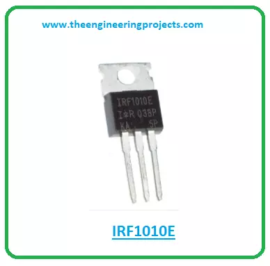
The IRF1010E is an N-channel power MOSFET that comes with low turn-on resistance and is mainly used in fast-switching applications. The maximum power dissipation of this device is 170W and the pulsed drain current is quite high i.e. 330A.
I suggest you buckle up as I’ll detail the complete Introduction to IRF1010E covering datasheet, pinout, features, and applications. Let’s get started.
Introduction to IRF1010E
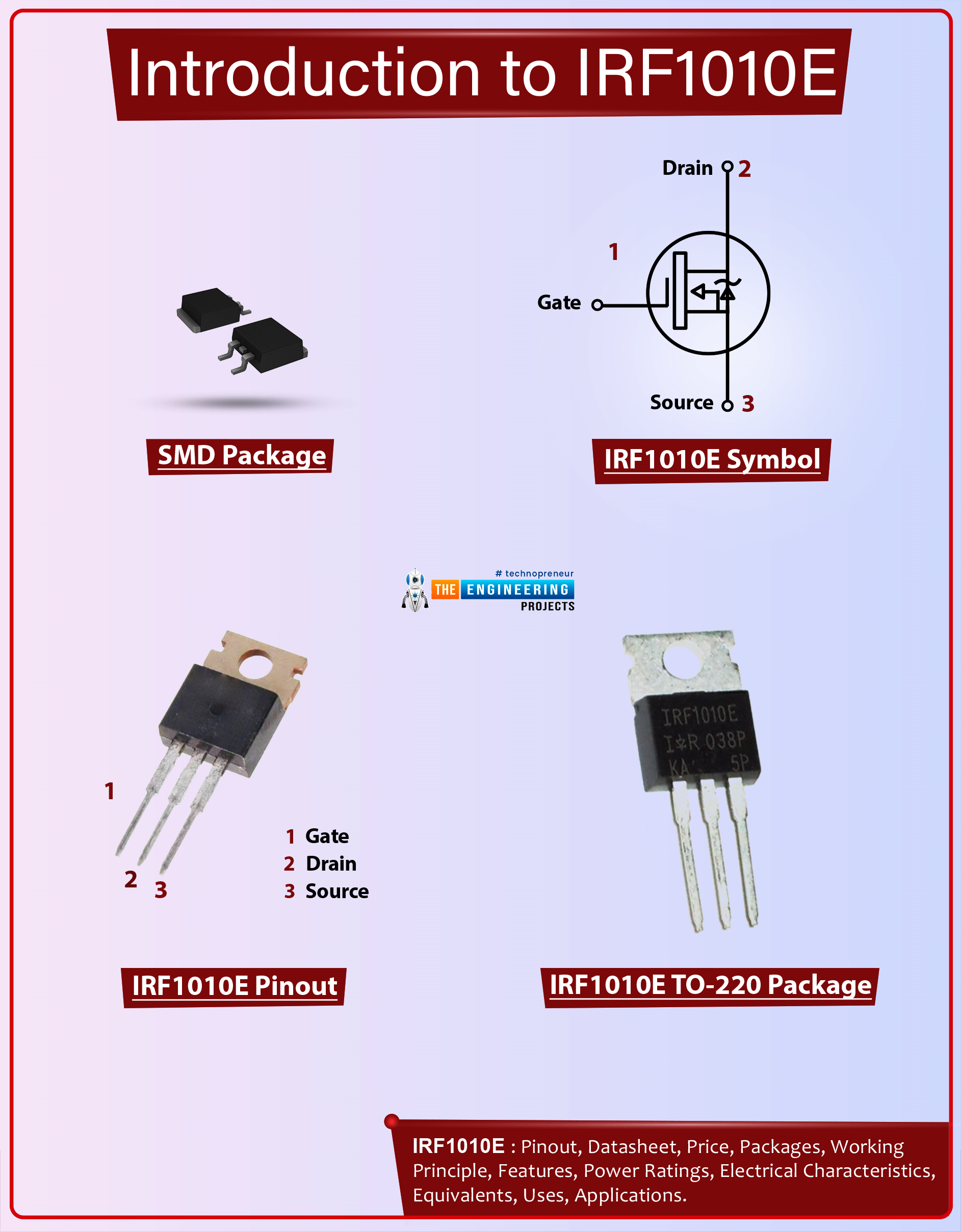
- The IRF1010E is an N-channel power MOSFET mainly employed for fast-switching applications.
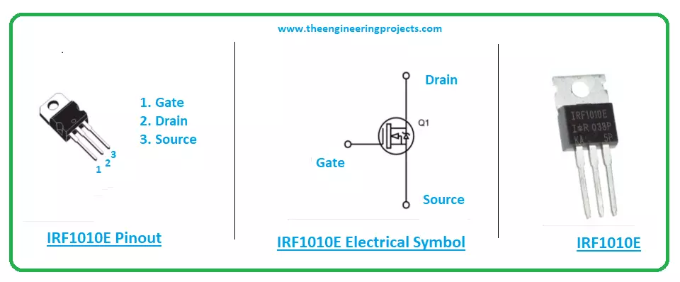
- This chip is a three-terminal device with terminals drain, source, and gate. It is a voltage-controlled device as opposed to a bipolar junction transistor that is a current-controlled device and comes with terminals: base, collector, and emitter.
- The gate terminal in IRF1010E is used for the biasing of the device while the source terminal is the area from where electrons enter the channel while the drain terminal is the area from where electrons leave the channel.
- The gate terminal stands between the source and drain terminals. And the channel width is handled by the voltage on the gate terminal.
- The main principle of this device is based on controlling the voltage and current between drain and source terminals. The MOS capacitor is the key component that plays a crucial role in the functionality of the device.
- The MOSFET works in two ways i.e. in depletion mode and enhancement mode. During depletion mode, when no voltage is applied across the gate terminal, there is maximum conductance across the channel. However, when the voltage is applied across the gate terminal, it results in decreasing the channel conductivity.
- While, on the other hand, the enhancement mode works exactly opposite to the depletion region. Here when there is no voltage, there is no conductance across the channel. While when voltage is applied, it results in increasing the conductance.
- There are two types of MOSFET available in the market i.e. P-channel MOSFET and N-channel MOSFET. This device IRF1010E falls under the category of N-channel MOSFET where electrons flow as the charge carriers in contrast to P-channel MOSFETs where holes are the major charge carriers.
- This IRF1010E MOSFET comes with low turn-ON resistance, making it a right fit for low-drop switching applications. The low drop results in low power loss, hence ensuring greater efficiency. This device is also used for high-efficiency applications.
IRF1010E Datasheet
It is wise to go through the datasheet before incorporating this device into your project. This datasheet features the main characteristics of the component. Click the link below to download the datasheet of IRF1010E.IRF1010E Pinout
The following figure represents the pinout diagram of IRF1010E.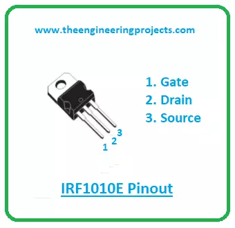
IRF1010E Features
The following are the main features of IRF1010E.- Developed with advanced process technology
- Used in Fast switching
- Fully avalanche rated
- Operating Temperature Max. = 175ºC
- The voltage across GATE and SOURCE Max. = 20 V
- Continuous current allowed through DRAIN Max. = 81A
- The voltage across DRAIN and SOURCE Max. = 60V
- It’s a Fifth generation HEXFET
- Pulsed DRAIN current Max. = 330A
- Power dissipation Max. = 170Watt
IRF1010E Alternatives
The following are the alternatives to IRF1010E.- IRFB4110
- IRFB4310Z
- IRFB4115
- IRFB4410
- IRF1407
- IRFB4110G
- IRFB4310ZG
Double-check the pinout of the alternatives before incorporating them into your project as the pinout of the alternatives might differ from the pinout of IRF1010E.
IRF1010E Applications
This device is used in the following applications.- Employed in speed control units
- Incorporated in PWM applications
- Used in Relay drivers
- Employed in Switch mode power supply
- Used in Lighting systems
- Used in any switching applications
That’s all for today. I hope you find this article helpful. If you have any questions, you can approach me in the section below. I’ll try to help you the best way I can. You’re most welcome to share your valuable feedback and suggestions around the content we share so we keep producing quality content customized to your exact needs and requirements. Thank you for reading the article.