


Advance Timer Functions in PLC Ladder Logic Programming


Believing in the essence of timers in ladder logic programming, we come today with a new tutorial in which we are going to show you all about timers, the types of timers, what’s inside timers’ block of parameters, variables, and bits. In addition, techniques for using timers will be explored, and for sure, we are going to practice what we learn using the simulator. So let’s get started with our tutorial.
Timers in ladder logic programming
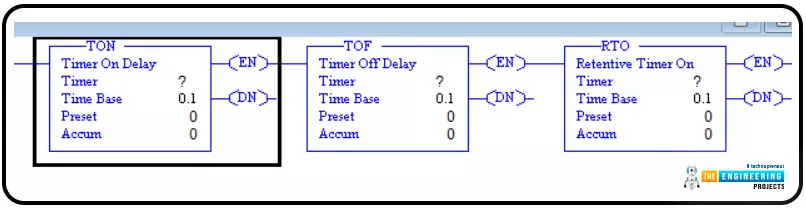
Guys, this is not the first time we’ve talked about timers. However, this time we are going to look into timers deeply and use the glasses of practical approach. So figure 1 shows the most important types of timers in ladder logic from left to right: the on-delay, off-delay, and retentive timers. There are differences in functionality. However, they all have the same parameters, variables, and bits. For example, the on-delay timer (TON) works by starting counting by getting the high logic state of its input. And bit goes ON when and only when the counter reaches the preset value. While the off-delay timer (OFF-DELAY) employs starting with the high logic of its Done bit once it has a high logic of its input. And when its high input stat is gone and turns to low. It starts counting until reaching the preset value, and then the done bit goes off. On the other hand, the retentive timer keeps accumulating the time while the input is energized until it reaches the preset value, at then the Done bit goes on. You can see, my friends, how are different in functionality to help you get a way for every problem related to timers. Despite that variety in behavior, they have the same data, as you can see in each timer block. So now, what are these data, and how can we utilize them in ladder logic programming? that is what we are going to learn together in this tutorial.
Timer data in PLC
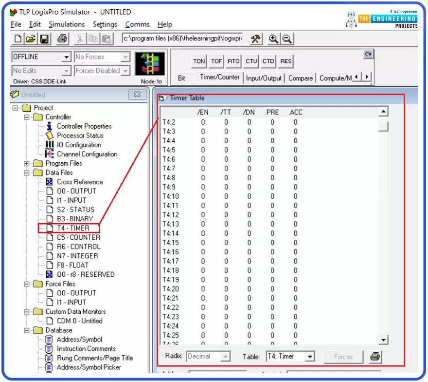
Well! Timer data can be demonstrated in figure 2. You can see guys in the tree view windows below; the data section shows the timers data in which there are dozens of timers you can use through long your program. But what does the data include? Well! The data has timer bits and variables, as shown on the right side of the window. The most important variables are the preset variable (PRE), in which we set the value of the time at which we require the timer to act ON. The other variable is the accumulator variable ACC that we use to know what the counted time is so far. The logic says the timer keeps increments accumulator until reaching the preset value. Okay, then what happens when the accumulator reaches the preset value? Exactly, the timer needs to indicate that he reaches the target. There are so-called timer bits like the timing bit TT that reports the timer is timing, and the DONE bit that tells the accumulator has reached the preset value. And also the EN bit that shows the completion of execution of the timing instruction.
Most Common PLC Timer Types
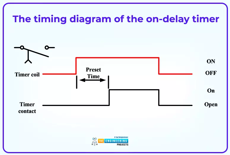
Well, timers can be categorized based on their functionality and the way they work. For instance, the ON-DELAY timer starts timing when it gets a trigger signal which is the high state of its input. By reaching the preset value, the output will have been energized as long as the input is high. Please, guys, see the timing diagram in Figure 3 which depicts the timing diagram of the input and output of the ON-DELAY timer. It shows the timer contact goes on after counting the preset time value since it receives a high logic on its input coil.
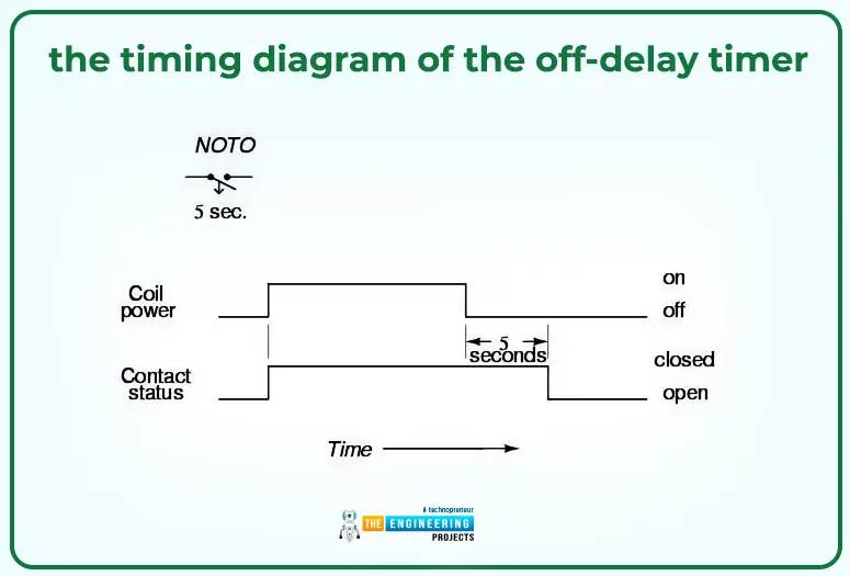
The second but same important kind of timer is the OFF-DELAY timer. This timer starts energizing its contact or output from the moment it receives high logic input. Then after that input goes low, the output remains high in the logic state for as long as the preset value has been specified. Please, my friends, find the operation cleared in figure 4 below, which demonstrates the operation by the language of the time. In this example, the timer coil has been energized, and its contact goes high. And when the coil de-energized, the contact remained high for 5 seconds which is the preset amount of time of the timer.
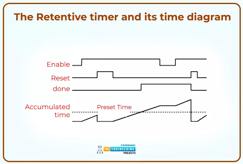
The third timer we are going to show today is the retentive timer. So what does that timer do? Well, that timer accumulates the time whenever its coil is ON. The timing diagram is shown below in figure 5. More details about the timing diagram of retentive timers, what figure 5 demonstrates. You can notice, my friends, as long as the input is high, the timer accumulator keeps accumulating the time until one reset signal appears, then it resets the time. But it returns back, accumulating the time whenever the input is true.
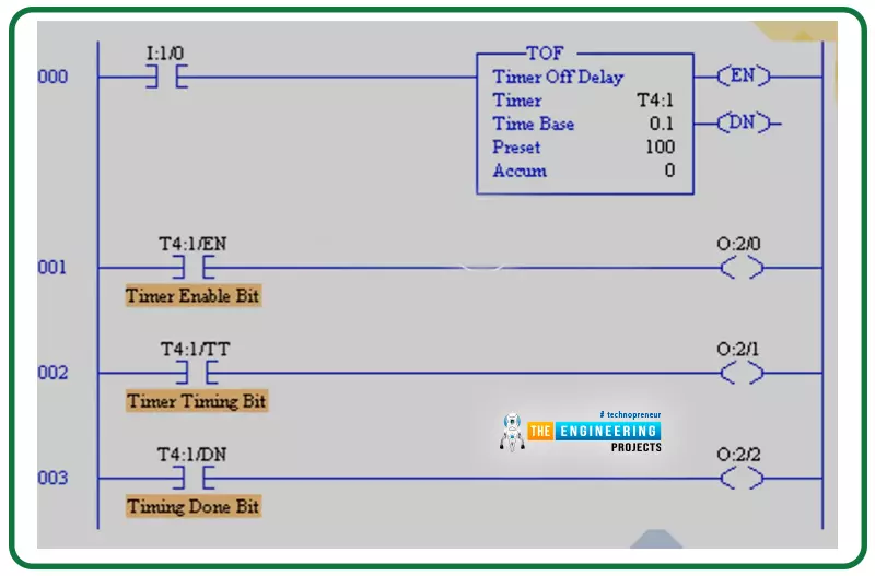
Now we will show some examples to let you understand how to employ the timer variables and bits as well. Figure 6 shows the timer block of an OFF-DELAY timer. You can see, guys, the timer’s name is T4:1, the time base is set to 00.1, and the preset value is set to 100, meaning it is designed to time for 10 seconds that can be determined by multiplying the time base to the preset value. Also, you can see that the first rung used input I:1/0 to enable the timer by energizing its coil. Rungs 1 to 3 show how you guys might use the timer bits. For example, in rung number 1, the enable bit of the timer is used to energize output O:2/0. Similarly, the timing bit TT of the timer is utilized to turn on output O:2/1 in rung 002. While the done bit DN energizes output O:2/2 as in rung 003.
Simulating one example
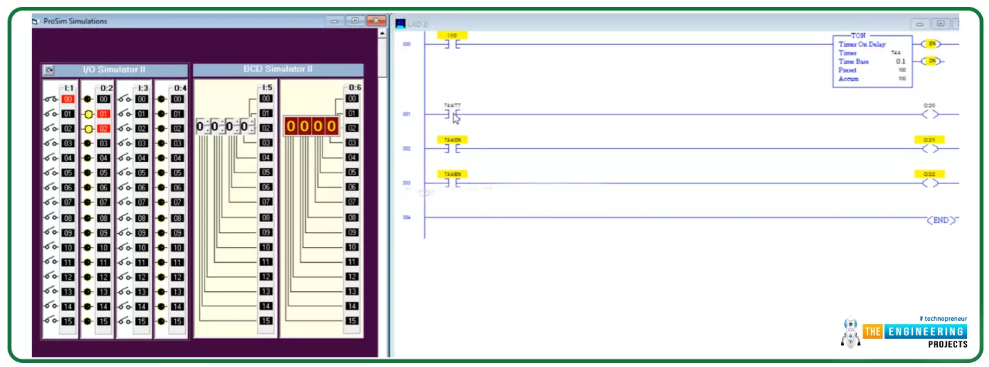
Here it is the simulation of one example to show how the timers bits and variables can set and used. In figure 7, the timer of type on-delay T4:4 is used and set to time for 10 seconds by setting the preset to 100 and the time base to one-tenth 0.1. the timer’s bits are used as you can see my friends to activate different outputs.
Example showing timers types
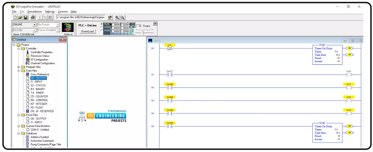
Another example demonstrated in figure 8 to show the on-delay and off-delay timers working together to fulfill the requested logic.
Retentive Timer example in Ladder Logic
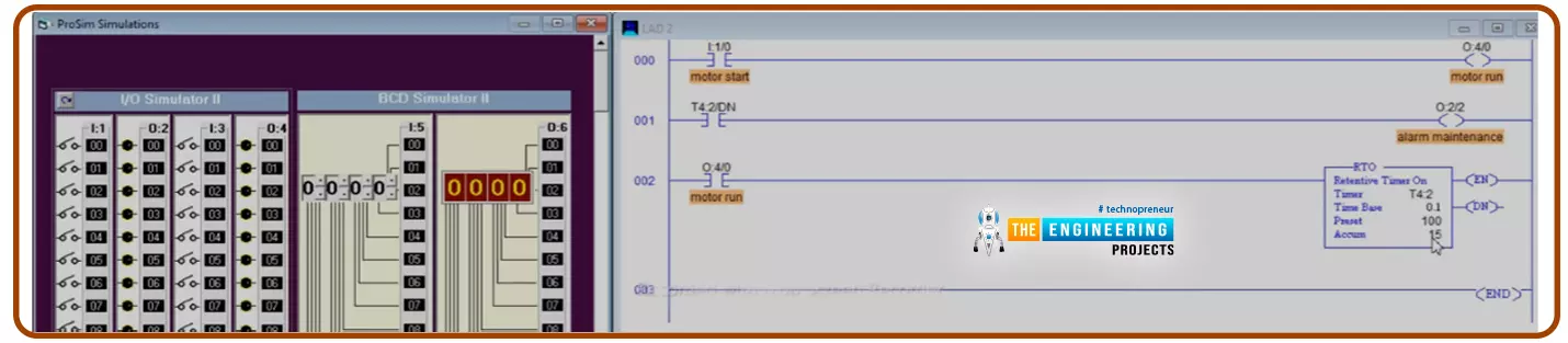
Figure 10 shows an example to demonstrate the utilization of a retentive timer type. You can see the timer block of the retentive timer RTO and how it is accumulating the time whenever the input is high without resetting when the input is turned off.
Timers programming techniques
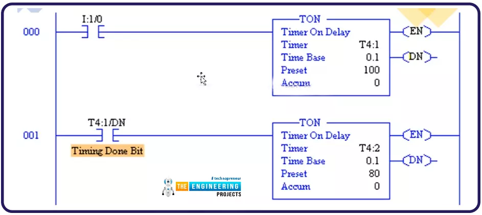
Going to one of the most important parts of our tutorial is how professionally you guys can use the timers to solve whatever problem you have. The techniques to use timers that come with experience. For example, figure 11 shows the cascading timing technique in which you can use multiple timers based on each other in a cascading way. You see, guys, how timer T4:2 depends on the Done bit of timer T4:1 in cascading approach. Why do we need to use two timers in such a way when we can use only one with a preset value equal to the sum of the two timers? That’s smart to be asked. But the answer also is intelligent, which tells us we might need to do some action in between. For example, when timer number one has done timing, we might energize one output, and after the second, we perform another action depending on the first timer.
Reset the timers in Ladder Logic
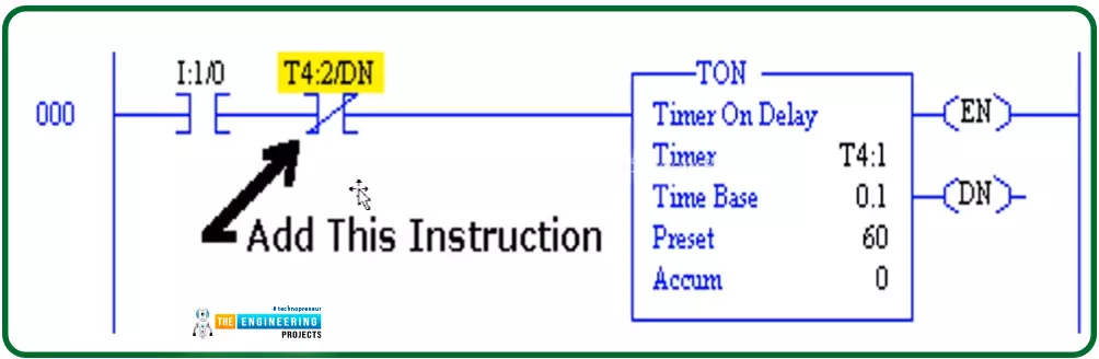
Figure 12 shows the technique to reset the timer by having one normal close contact in the way of its input to control energizing the timer coil. In that very example demonstrated by figure 12, the timer Done bit itself is used to reset the timer, meaning that when the time contact acted ON, it is the time to reset the timer and like that, we can guarantee the timer keeps repeating the process forever.
And at that point, I would like to thank all my friends for following me till the end of that tutorial, and I hope you have learnt some knowledge and enjoyed practicing one of the most important topics in ladder logic programming, Timers. For recapping have nailed the timers by demonstrating the variables and bits of the timers and the types and techniques of using the timers to flexibly and professionally can deal with different situations and solve any problems related to using the time.


