Advance Counter Functions in PLC Ladder Logic


Hi, my friends. Welcome to share a new tutorial in our ladder logic programming series. Today we will discuss counters in ladder logic programming using an expert’s view. So let’s wear the glasses of an expert in ladder logic programming and look deeply into counters, the types of counters, their variables and bits. In addition, techniques of using counters to solve a different kinds of problems that need counting. And without questions like every time, we will enjoy practicing programming and simulating all about counters. So with no further delay, let’s jump into our tutorial and nail that counters.
Counters in real life
Tell me, guys, if you can imagine an industrial project or machine that does not need to count parts, products, or processing cycles. Actually, in most cases in industry and practical operations, you will find counters everywhere you visit production lines or operating machines. So now, what are the types of counters and what is inside or belongs to counters, their variables and bits? Also, what are the techniques for utilizing counters in ladder logic programming?
Counter Types
As regards functionality, counters can be divided into count up and count down, as shown in figure 1. Counter-up and down instruction blocks are shown in CTU and CTD. One is to count up, and the other is used to count down. They are different in functionality. However, they have the same variables, parameters, and data bits. So let’s discuss all this data belonging to counters.

Counter data bits
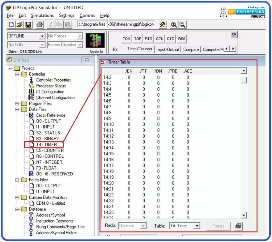
Figure 2 images the data of counters. On the left tree, you guys notice the counters in the data files and on the right, see many counters that you can use in your ladder logic program. Also, the main variables are the preset value and the accumulator value by which you tell the program the counter will count up or down to what value. Also, you should know the left side of the rung is the input to the counter to activate it and let it counts when the input is high. While the right side is the output data bit of the counter which is the enable EN bit that tells the counter block has run okay. And the done bit DN that informs the counter reached the desired preset value by turning into high when the accumulator variable ACCUM goes equal to the PRESET value.

How to use counters in PLC?
Figure 3 shows the best practice for utilizing counters and handling their logic. In the first rung, we used input I:1/0 to control the CTU counter set to count up to 10. So every time the input to the counter turns from low to high, the counter will count up by incrementing the ACCUM. Also, we have used the RES instruction to reset the counter at any time by having the input I:1/1. So by having the input I:1/1 turned to high, the counter’s accum will reset to zero. Now moving to the important part that provides the clue to process and handle counters. Starting from rung 3, the comparison instructions are used to check the ACCUM and control the outputs according to the logic we designed for. For example, in rung number 3, the EQU instruction compares the accumulator C5:1.ACC to zero to check if they are equal and if so, it energizes output O:20/0. In contrast, the NEQ compares instructions to check the inequality of the source C5:1.ACC and zero to decide the next state of output O:2/0. Furthermore, Runge 004 combines greater than GTR and less than instructions to check if the accumulator value is between two values and decide the state of the output on the right. Continuing further, the greater than or equal GTE and less than or equal LTE are used to check the accumulator as well but considering the boundary values.

Counter example with simulation
Figure 4 demonstrates an example of the counter in which input I:1/1 has been used to control the counter input, and input I:1/2 is used to reset the counter. Also, in the third runge, the done bit of the counter controls the state of output O:4/0.

Simulating counter example
Figure 5 shows the simulation of the counter’s example. It shows the counter counts up every transition from low to high of the input I:1/1. Also, it shows that the output’s state of O:4/0 has come to high when the counter’s accumulator has reached the value of the preset value.

Also, as you see, friends, when input I:1/2 has clicked, the counter accumulator has been reset to zero thanks to utilizing the reset instruction RES.

Example of using comparison instruction with counters
Figure 7 demonstrates how using the comparison instructions to handle counters by comparing the accumulator of the counters, checking its value and controlling outputs accordingly. For example, in rung 002, output O:4/0 will go high when the counter’s done bit goes high or when it counts to 10. Also, output O: 4/4 will be turned to high in rung 004 when the accumulator of the counter is something between 3 and 7 but not 3 and 7 themselves. To include boundaries 3 and 7, the comparison instruction less than or equal LTE and greater than or equal GTE are used as rung 005 to control O:4/7. Also in rung 005. The compare instruction EQ is used to decide the state of output Q:4/6. In the simulated running example, when the counter’s accumulator was equal to 3, outputs O:4/7 and O:4/6 turned to true based on the results of the comparison instructions.

Tracking the data table
Exploring the data files on the left part of the view, you can also see the values and states of the counter’s variables and data bits. The value PRE is 10; the accumulator variable ACC is 10. So, the done bit DN is true or 1. Also, the function of the counter with cunting up is shown as 1.

Small PLC project using counters
After showing how to use the comparison instructions and introducing the counter variables and data bits, it is time to do something with counters. And here it is in figure 9; you can see a funny example of singers. In that example, we use two counters, CTU and CTD, to count up and down. The program utilizes flag B3:0/1 to manage which counter will be activated. As you see in rung number 1, when b3:0/1 is false, the counter CTU will be active to count up. By the time the counter reaches 10, its done bit turns high to activate flag B3:0/1. Then, the counter CTD is active to count back down to zero. And finally, when the CTD counts down until reaching zero, the flag B3:0/1 has turned off using unlatch (U) instruction to repeat the process again and again. So let’s see some tests for the implemented code to check if it is correct or if something needs to be amended.

Figure 10 shows the counter CTU is counting up every chance the input I:0/1 turns from OFF to ON.

Figure 11 shows how the logic turns to activate CTD after counter CTU reaches its preset value by flipping flag B3:0/1.

Figure 12 shows that the process has returned to count up after the accumulator has reached zero.

Now, guys, we have nailed counters showing the variables and related data bits and techniques of utilizing the comparison instructions to handle the counters logically. Thanks, guys, for following me up here . I hope you have enjoyed learning and practicing the counters in ladder logic programming. I hope to meet again with an interesting tutorial of our series of ladder logic programming.