4-Floor Elevator Project with PLC Ladder Logic (Part 2)


Hi, my friends and welcome back. I am happy to meet you again with a new tutorial of our PLC ladder logic programming series tutorials. Today we will complete what we started the last tutorial on the Elevator control project. We have a bunch of duties to complete together today. So let’s save time and jump into work immediately.
Project description:
Figure one shows the details that might help me describe the project between our hands. We have an elevator car that travels up and down and can stop on one of four floors based on the passengers’ requests. We have 6 push buttons on the wall next to the elevator door that can send requests to call the elevator. In addition, there is a control panel inside the elevator cabinet in which there are push buttons to request stations to reach floors 1, 2, 3, or 4. So now we are requested to manage all the scenarios and all requests received from inside and outside the elevator considering the priority of these requests to save energy and time management for the elevator traveling route. In the next section, the detailed requirements are listed.

The project requirements
The elevator should save all requests from the time they are requested until they are processed and cleared from the to-do list.
The elevator should prioritize the requests in their direction of movement. For example, while he goes down, the requests for places located below his position will be given priority to do first. Similarly, when he goes up, the requests above the position where he is will be given priority. In that we, the waiting time will be reduced, and the energy and overall travelling distance will also be minimized. Because we have a lot to present in this significant project, let’s move on directly to the design and the ladder logic program that handles these requirements.
The design and logic of Elevator System
As usual, we are going to apply the divide-and-conquer rule. So the project will be divided into subtasks, and each task will be managed by one subroutine all subroutines are called in the main routine in sequence. Figure 2 shows the program structure which is composed of 5 subroutines. In the first routine, all initializations are called to be executed. So what’s in these subroutines? That is what we are going to show you below. So please follow up, my friends.

Figure 1 shows the ladder logic code of the first subroutine that initializes the work to start with the first floor as the initial position and going up as the initial moving direction and activate the action of performing the subsequent request or waiting for an incoming one.

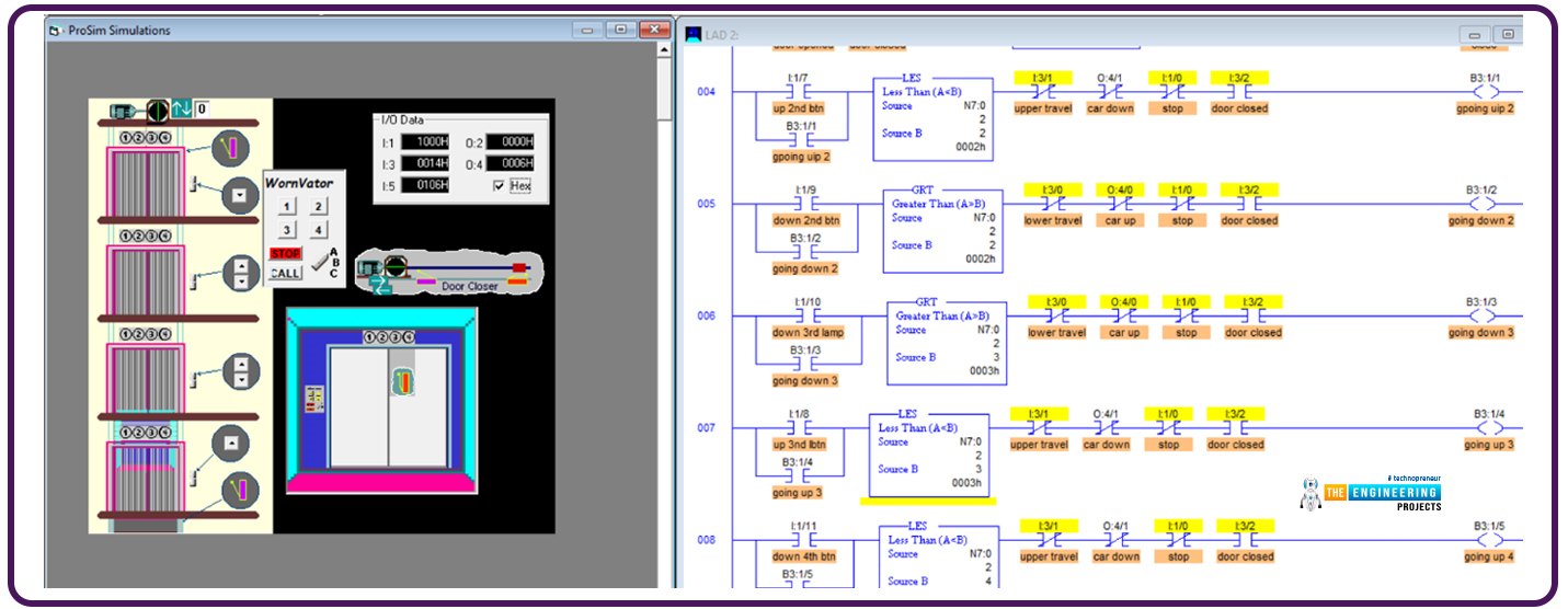
The next subroutine is the heart of the logic, as it saves the requests and energizes the light indicators of the requested doors. Figure 3 shows a portion of the routine’s ladder logic code. As you notice, my friends, the first line is to tell the compiler that this is the start of the subroutine. The rung number 1 check if the request push button of the first floor inside the elevator’s car has been pressed and the elevator is not on the first floor; it will light the button lamp to show there is one request in the queue until the time comes to perform that request then the light will be turned off as we will demonstrate to you, guys. The next rungs, rungs number 2, 3, and 4, do the same for the corresponding keys inside the elevator’s car. If a push button is pressed, and its requested floor is not the current floor where the elevator is, then the corresponding lamp indicator is lighted, showing the request is saved in the queue, and when it is processed, the lamp indicator will be turned off. Now, moving on in the code, rung number 5 handles the outdoor request from pressing the first floor up push button. It simply checks the floor location. If it is not on the first floor, it lights; the lamp indicator of that push button shows that the request is in progress and will be turned off once it is processed. The following rungs do similarly the same function. But notice we have one push button for floors 1 and 4 while there are 2 push buttons for floors 2 and 3. So there are two rungs for handling the up and down direction requests.

One remaining thing for this subroutine is that the last rung confirms that when no requests are there so, the light on the first floor is turned on, showing that the elevator is on the first floor. Now my friends, let’s move to the next subroutine.

The next subroutine is called “track the vertical travel.” As you see, guys, the code checks in rung number 1 if the elevator is on the first floor, then it lit the first-floor light indicator and unlatched or de-energized the previous floor light, which is on the second floor and stops and opens the door. Now, when it reaches the second floor, indicated by the I:5 encoder, it lit the second floor and de-energized the lights of the next floors up and down, which are the first and third floors. Also, it checks if the second floor is being requested or in the queue list, then it stops the elevator and opens the door for getting or charging people who requested the second floor.

Figure 7 shows the ladder logic code of the second and last part of this routine; rung number 3, for example, checks if the elevator has reached the third floor; in this case, it lit the third-floor lamp indicator and turned off the next floors’ lamp indicators, i.e. floor 2 when it moves up from floor 2 to floor 3, or floor 4 when it goes down from floor 4 to floor 3. Also, if it goes down and the GO-Down request of the third floor is pressed, meaning there is a request in the queue, then it stops the elevator and opens the door for charging or discharging people who target the third floor. But, if it is going down and the Go-down, it stops the elevator and opens the door for charging or discharging the people. And the last rung, number 4, handles the 4th-floor requests. If it is on the 4th floor, it just lights the light indicator on the 4th floor and turns the light on the 3rd floor.

Now, my friends, the next routine is called “stop and open,” that handles opening the door at each destination. Figure 8 shows the logic; in rung number 1, if the door is not open for 2 seconds, then it is open the door, gives some time and then performs the subsequent request. When the door is opened, the request for the first floor is cleared. When it reaches floor number 2, and the door opens, if it goes up, clear the floor lightly and push the button to request the second floor, similarly, for the third and fourth floors.

Figure 9 shows the ladder logic code of the routine that decides which door will be bypassed and closing the door and go. It is called “ Do next or wait.” You can see, guys, it easily compares the moving direction and the requests in the queue based on the light status of the push buttons of all floors. Then bypass and resume with the door closed or wait and open the door for charging or discharging people.

Figure 10 shows the routine for closing the door at destinations. The routine is called “close door and move.” It simply checks if the door is closed and going up is requested, then lunch the move up the direction. But, if it is requested to move down, then latch the motor moving down. If no requests are moving up or down, enable the between-floors status. Now, my friends, we have explored all subroutines, and the time to test our logic and ladder logic program and subroutines has come. So let’s see if it is correct or needs some amendments.

Testing the ladder logic code
Figure 11 shows the initial state of the program while the elevator stops at the first floor, and the light indicators show the light of the first floor is lit, as you can see, my friends. Now let us command the push buttons requesting many requests to test.

From the initial position where the elevator is on the first floor, figure 12 shows the elevator has been requested as follows: on the second floor, it is requested to move up. On the third floor, it is requested to move down. On the fourth floor, it is requested to move down.
According to the requests and the sequences, it starts the journey from the first floor and stops at the second floor, as shown in figure 12.

Continuing his journey, he bypasses the third floor because it needs to go down. Show it gives priority to the request on the 4th floor, which is in his moving direction, as shown in figure 13.

Now, after reaching the most up, it changes direction and goes down to reach the third floor, which is the last request, as shown in figure 14. Notice, my friends, every time it reaches one requested place, it clears the light of the belonging request.

What’s next???
Clearly, the test successfully showed one scenario with all the test cases of moving, stopping, and bypassing. Thank you, friends, for following up on these points, and I hope you have enjoyed the project we have done together in this tutorial. Also, I promise the next tutorial will come with a new project from real life and learn more and enjoy practicing ladder logic programing together. So stay safe and be ready for our next tutorial.