


Four floors Elevator using ladder logic programming


Hello, my friends and welcome back with one new tutorial of our ladder logic programming series. Today I am bringing one exciting project which you can see everywhere, in your home, work, and public places, which is an elevator. We will design a solution using plc ladder logic programming, which drives the elevator. Our elevator is composed of 4 floors and has all capabilities of large-scale elevators. So let’s get started and save time and jump into our tutorial.
Elevator Project
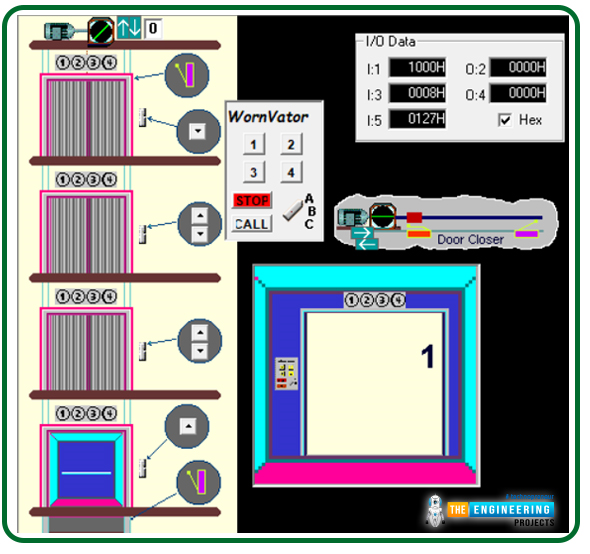
As you can see, Everyone figure 1 depicts the complete scene of the project and tells that the elevator we will manage has four floors to visit. On the first floor, there is only one outer request to call the car from any floor above, i.e. from floor 2, floor 3, or floor 4. While on the second floor, there are two request buttons to get the car from up or down floors and the same for floor 3. But floor 4, the last floor, has one request button to bring the elevator from the below floors, i.e. floors 1, 2, or 3. Also, the figure shows the request buttons inside the elevator car. There are request buttons for each floor, one-stop button, and one call button for emergencies. Now let’s move on to the inputs and outputs we will use in our logic:
Project inputs and outputs (IOs)
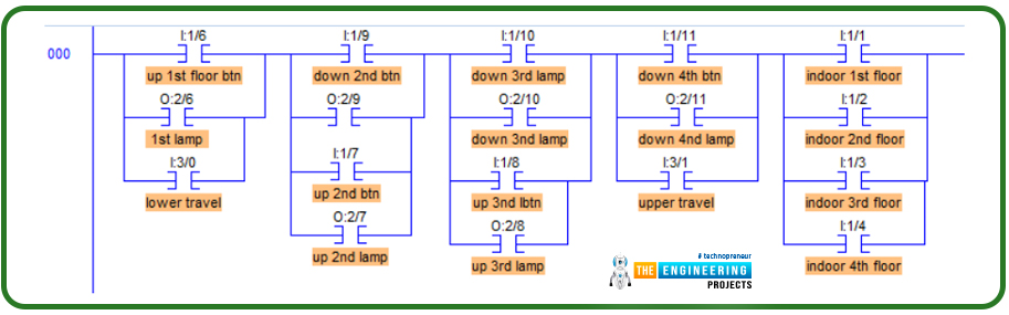
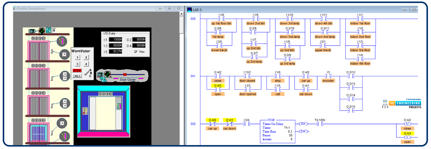
Smartly, we wrote one rung ladder logic as shown in figure 2, which does nothing but show the IOs the project has and names each IO with the descriptive name. We typically do such a rung for listing all IOs in one place to see the status of all IOs with one look. So what IOs do we have in this project? Well! You can see the request push button on the first floor from right to left and connected to input I:1/6. Also, the lamp indicator shows that the request is in progress. That indicator is connected to output O:2/6. In the second column, you can notice my friend’s two request push buttons connected to digital inputs I:1/9 and I:1/7. Also, for each request push button, there is an indicator lamp. The indicators of up and down requests for the second floor are connected to digital outputs O:2/9 and O:2/7.Similarly, in the next column, two push buttons request the elevator car to come from up or down; the request push buttons of the third floor are connected to digital inputs I:1/10 and I:1/8. Also, indicator lamps of the demands of the third floor are connected to digital outputs O:2/10 and O:2/8. And floor four has only one request push button and one indicator lamp associated with I:1/11 and O:2/11, respectively. It is essential to let you know that there are two safety limit switches to govern the travel limit in up and down directions. Digital input I:3/0, the one represents the lower limit travel while I:1/4 holds the upper limit travel signal. Also, there are inputs for the indoor control panel, as shown in the figure below. For example, indoor floor requests are connected to digital input I:1/1, I:1/2, I:1/3, and I:1/4 for requesting the first, second, third, and fourth floors. In addition, there is one push button to stop and another to call.
Design of elevator
Once more, let me remind you, my friends, that the best way to make it easy is to divide and conquer, meaning we break down the whole mission into sub-tasks and complete them to integrate at the end of the day for having the entire task achieved. Now, what are the requirements? Good, you ask such a question. Well! Our clients provided us with the image shown in figure 1 that gave us some details, but we still need to list the requirements and validate them with the customer before going further. That is crucial, my friends, because going further without confirmation of the conditions might yield some conflict later at a point in time. We will have made many efforts to cost many working hours that we want to retain. So again, what are the requirements? We need to recognize the position where the elevator is at any moment. Also, we need to command the elevator to go up or down based on where it is and the requested position. So now let’s divide the project into two main tasks. Determining the elevator position is our first one, and performing the requests will be the second task. So now, let’s move forward to the logic and coding of our ladder logic program.
Elevator ladder logic task 1
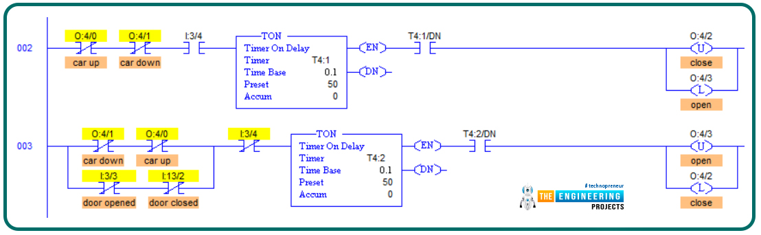
As we have mentioned earlier, in task 1, we want to determine the position of the elevator to decide where to direct the elevator up or down when one request comes. For example, you assume the elevator is on the 3rd floor, and a request comes from the second floor to call the elevator car. So, in this case, the logic of the program should command the elevator to go down. But if it was located on the 1st floor, in that case, it should direct in the up direction. Before going further in the position determination, we will show you how to manage the elevator door. Because we can not command the elevator to move while the door is open, figure 3 shows the door control lines of code in ladder logic programming. In rung number 2, we design the logic so that if the car is not moving up or down for a while, the door will be commanded to open by using the latch and unlatch command. In rung number 4, the door will be closed when the elevator does not move up or down, and the door is not opened or closed.
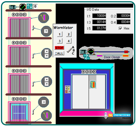
For testing the opening and closing management of the elevator door, Figures 4 and 5 show the door while opening and closing actions.
Ladder logic of elevator position
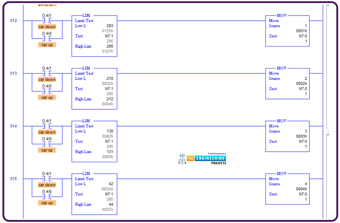
Figure 5.1 shows the ladder logic code for determining the elevator position; it utilizes the encoder’s feedback or reading and compares it using the limit instruction given the limit of each floor. For example, if the value reported by the encoder is between 293 to 295, which is the limit position of the first floor so, save one into the variable N7:0 that holds the current floor where the elevator dwells. And similarly, decide on the second, third, and fourth floors based on each floor's limit and the encoder's reading.
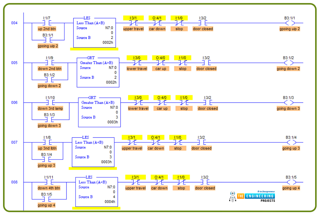
Now my friends, let’s move on to describing the code of the program step by step. Figure 6 depicts the ladder logic of the request handling logic. As you can see, my friends, in rung number 4, the requests from the second floor are being handled. When a request to move upward comes from the second floor, we test the elevator’s current position. If it is less than the requested position, which is floor 2, then it would go up. But if the position of the elevator is the upper floor, i.e. the 3rd or the 4th floor, then it should go down as instructed thanks to rung number 5. So let’s test this logic and see if it fulfills the requirements.
In the next step, after knowing the direction in which the elevator should move, we code the commands to drive the motor to move up or down, as in figure 6.1, using rungs 10 and 11.
Testing the second-floor requests
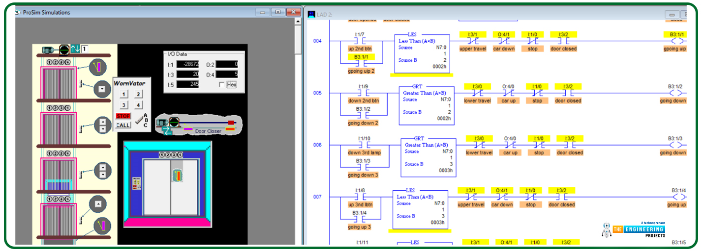
Figure 7 shows the first scenario when the elevator was stopped on the first floor and was requested from the second floor. It shows the elevator goes up to its new requested target.
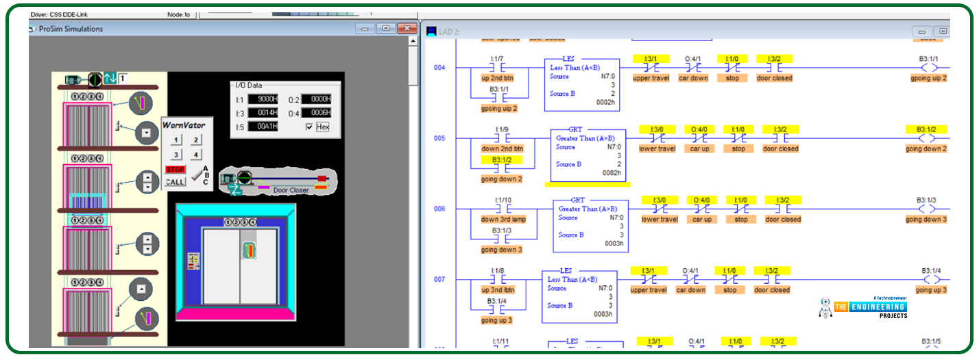
Figure 8 shows the second scenario when the elevator was stopped on the 3rd floor and was requested from the second floor. It shows the elevator goes down to its new requested target.
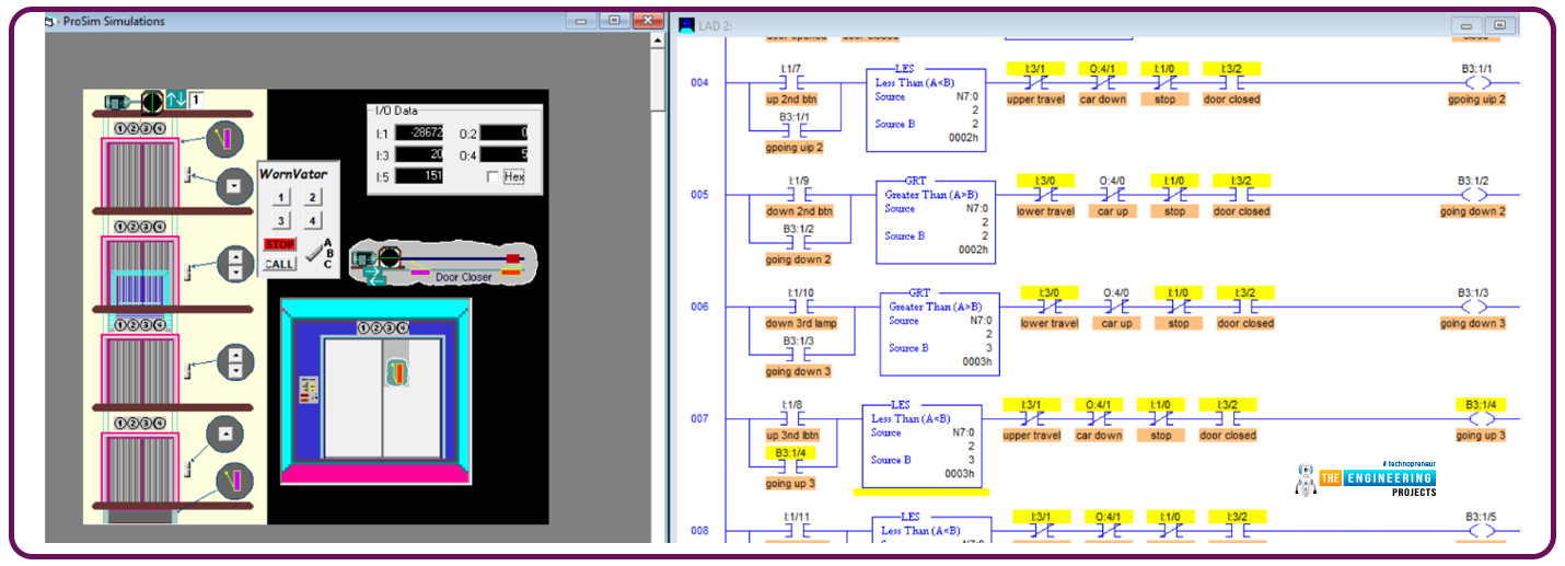
Figure 9 shows another test scenario when the elevator is requested to move from the second to the third floor. Success is the result shown in figure 9 as it shows the elevator is moving up from the source place to the destination, the third floor,
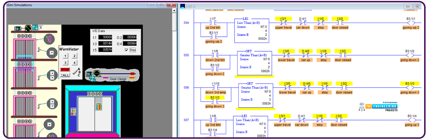
Figure 10 depicts another test scenario of a request initiated from the third floor when the elevator is requested to move from the fourth to the third floor. Success is the result shown in figure 10 as it shows the elevator is moving down from the source place, the fourth floor, to the destination, the third floor,
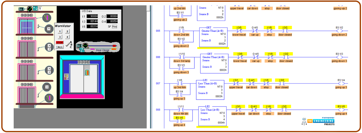
Figure 11 demonstrates another test scenario of a request initiated from the 4th floor when the elevator is requested to move from the third floor. The elevator moves up from the source place, the 3rd floor, to the destination, the fourth floor,
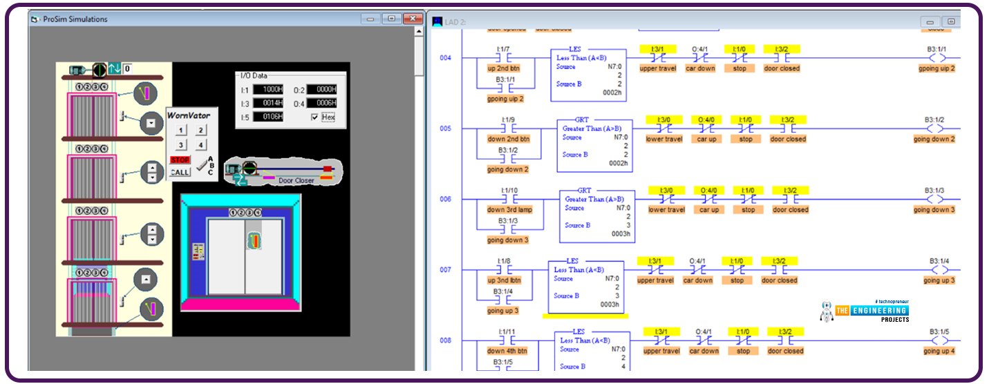
Figure 12 shows another test scenario of a request initiated from the first floor when the elevator is requested to move from the third floor. The elevator moves down from the source place, the 3rd floor, to the destination, the 1st floor.
What’s next???
First of all, I hope you have enjoyed the elevator project; please go through the tutorial and try to code the ladder logic and test it yourself for the best gain you can get from the tutorial. We have presented in this tutorial only some of it; we have done much great work, but we still have much work to do to complete the elevator project. So next time, the remaining project logic will be demonstrated, and you will enjoy learning and practicing ladder logic programming. So please stay safe and be ready for our following tutorial.


