Hi readers! I hope you are doing well and learning new things daily. Today, we have a detailed overview of the MAP(Manifold Absolute Pressure) Sensor, its working principle, types, structure, and features. The Manifold Absolute Pressure (MAP) sensor is a crucial element in a vehicle's engine to control pressure. The MAP sensor measures the pressure inside the intake manifold and transmits this data to the ECU so that fuel injection, ignition timing, and air-fuel mixture can be optimized. The MAP sensor is used to ensure engine efficiency, performance, and fuel economy.
The MAP sensor functions by the transformation of manifold pressure variations into an electrical signal, which is then interpreted by the ECU to calculate engine load. It is complemented by other sensors, including the Mass Air Flow (MAF) sensor and the Throttle Position Sensor (TPS), to increase fuel delivery precision.
MAP sensors are available in analog and digital forms, with different types depending on absolute and gauge pressure measurements. A faulty MAP sensor may cause poor fuel efficiency, engine misfire, or stalling, which necessitates maintaining smooth engine performance.
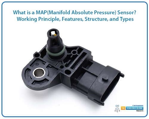
This article discusses the datasheet, working operation, characteristics, design, and MAP sensor types and their comparison in exhaustive detail.
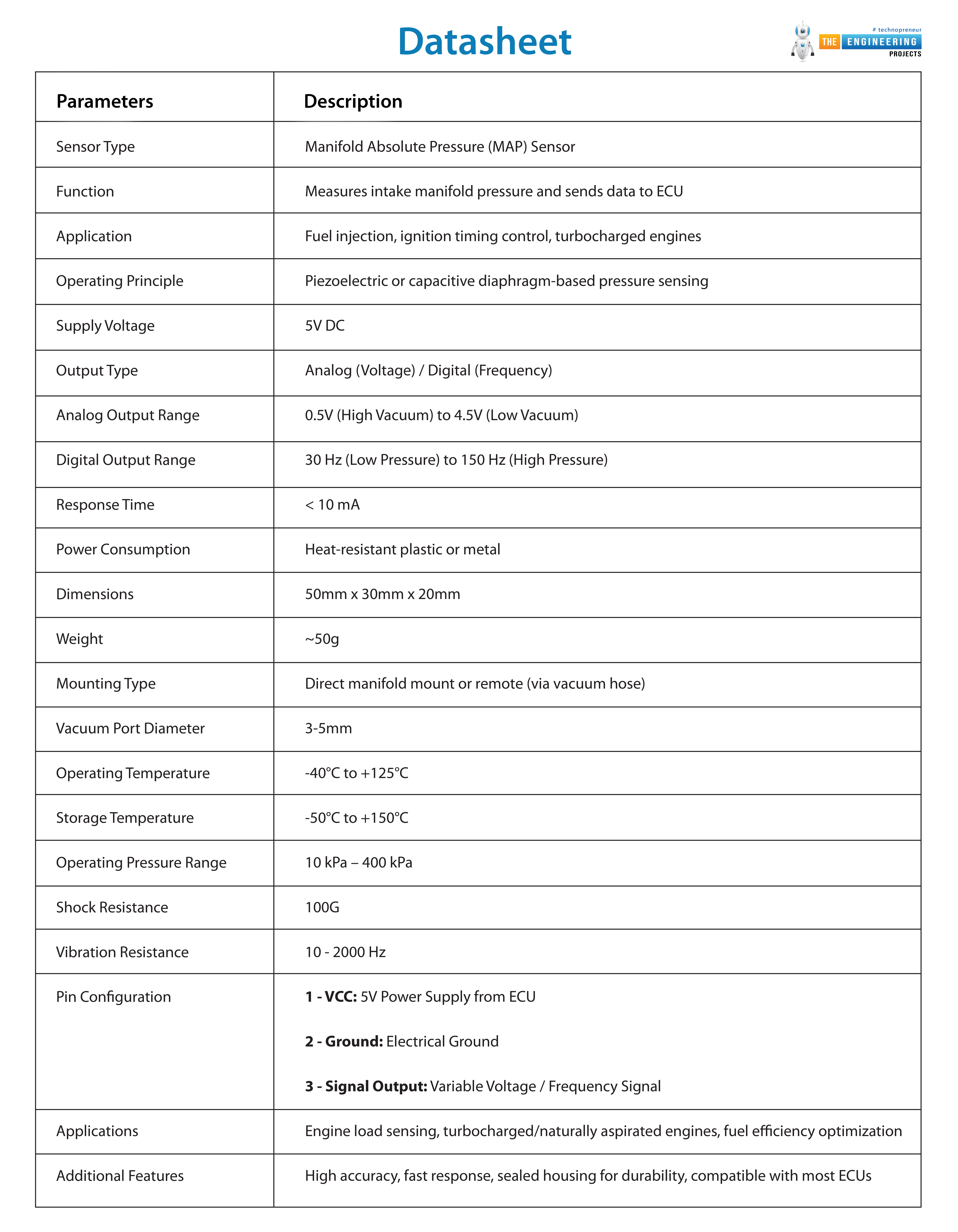
Datasheet:
Parameters |
Description |
Sensor Type |
Manifold Absolute Pressure (MAP) Sensor |
Function |
Measures intake manifold pressure and sends data to ECU |
Application |
Fuel injection, ignition timing control, turbocharged engines |
Operating Principle |
Piezoelectric or capacitive diaphragm-based pressure sensing |
Supply Voltage |
5V DC |
Output Type |
Analog (Voltage) / Digital (Frequency) |
Analog Output Range |
0.5V (High Vacuum) to 4.5V (Low Vacuum) |
Digital Output Range |
30 Hz (Low Pressure) to 150 Hz (High Pressure) |
Response Time |
< 10 mA |
Power Consumption |
Heat-resistant plastic or metal |
Dimensions |
50mm x 30mm x 20mm |
Weight |
~50g |
Mounting Type |
Direct manifold mount or remote (via vacuum hose) |
Vacuum Port Diameter |
3-5mm |
Operating Temperature |
-40°C to +125°C |
Storage Temperature |
-50°C to +150°C |
Operating Pressure Range |
10 kPa – 400 kPa |
Shock Resistance |
100G |
Vibration Resistance |
10 - 2000 Hz |
Pin Configuration |
1 - VCC: 5V Power Supply from ECU 2 - Ground: Electrical Ground 3 - Signal Output: Variable Voltage / Frequency Signal |
Applications |
Engine load sensing, turbocharged/naturally aspirated engines, fuel efficiency optimization |
Additional Features |
High accuracy, fast response, sealed housing for durability, compatible with most ECUs |
Working Principle of a MAP Sensor:
The internal combustion engine depends on a Manifold Absolute Pressure (MAP) sensor to operate because this device serves as an integral electronic control component. The sensor acts by identifying absolute intake manifold pressure before it produces electrical data for transfer to the Engine Control Unit (ECU). Through the sensor data, the ECU determines engine load which leads to adjustments of air-fuel mixture and ignition timing for efficient combustion as well as peak engine performance and lowest emissions possible.
1. Measuring Intake Manifold Pressure:
The operating engine attracts air into the intake manifold through which pressure changes correspond to throttle positioning, combined with engine speed and loading conditions. Live pressure readings from the MAP sensor are automatically sent to the ECU as constant feedback.
During wide-open throttle (WOT) conditions, the intake manifold pressure rises because the air intake becomes stronger. The MAP sensor notices this high pressure and provides a higher voltage signal to the ECU. The ECU raises the fuel injection to maintain a correct air-fuel ratio.
The amount of pressure in the manifold stays at an intermediate level while the throttle remains partially closed. The ECU receives a moderate voltage signal from the MAP sensor when the sensor detects intermediate pressure within the system.
The throttle remains mostly closed at idle and deceleration periods thus creating a high vacuum in the intake manifold that results in low absolute pressure. A weak signal spanning from the MAP sensor reaches the ECU while detecting these minimal pressure conditions. The ECU decreases fuel injection to avoid fuel wastage and emissions.
2. Conversion of Pressure into an Electrical Signal:
The MAP sensor works with a piezoelectric or capacitive sensing element that responds to manifold pressure changes. The element alters its electrical resistance or capacitance when exposed to varying pressure levels. The changes are processed in an electrical voltage signal, which is transmitted to the ECU.
Increased manifold pressure (low vacuum) gives a higher voltage output (~4.5V at WOT).
Lower manifold pressure (high vacuum) produces a lower voltage output (~0.5V under idle).
The ECU constantly checks this signal to make the proper fuel injection amount and ignition timing decisions for optimal engine performance.
3. ECU Interpretation and Adjustments:
After receiving the MAP sensor's pressure values, the ECU makes adjustments in real-time to various engine parameters:
Fuel Injection Control:
The amount of fuel injected is decided by the ECU using manifold pressure. A greater pressure indicates more air entering, hence more fuel to be injected. A lower pressure indicates less air entering, hence a reduction in the fuel to be injected.
Ignition Timing Adjustment:
The MAP sensor also assists the ECU in adjusting the ignition timing. At high load (greater pressure), the ECU retards the ignition timing for peak power. At low load (lesser pressure), the ECU can retard the ignition timing to increase fuel economy and lower emissions.
Turbocharger Boost Control:
In turbocharged engines, the ECU controls boost pressure using MAP sensor information. It keeps the turbocharger from overpressurizing to a dangerous level, causing engine damage.
4. Role of the MAP Sensor in Engine Efficiency:
The MAP sensor ensures the following:
Effective fuel burning is achieved by maintaining the correct air-fuel mixture.
Optimized engine operation by tuning ignition timing and fuel injection.
Lower emissions by avoiding too much fuel flow.
The engine achieves smooth acceleration from an idle state due to its stable operating condition in varying driving conditions.
The MAP sensor operates continuously to monitor intake manifold pressure enabling modern powertrains to reach better fuel efficiency and reduce pollutants while delivering an improved driving experience.
Features of MAP:
1. Real-time Pressure Monitoring:
Absolute pressure inside the intake manifold is permanently evaluated by the MAP sensor. The ECU receives a continuous flow of live information from the sensors which lets it change fuel delivery and ignition timing while factoring engine load and atmospheric pressure changes. Under all driving circumstances from idle to maximum acceleration, the system delivers optimal run performance.
2. High Sensitivity and Accuracy:
MAP sensors are engineered to sense even minor pressure changes. By achieving such accuracy the air-fuel ratio remains perfect which leads to reduced emissions and higher fuel efficiency. Today's MAP sensors incorporate either piezoelectric or capacitive sensing components allowing high-precision measurements together with rapid reactions.
3. Fast Response Time:
Because engine conditions fluctuate quickly, the MAP sensor needs to respond quickly to pressure changes. Quick response time guarantees that the ECU can adjust in real time, avoiding engine knock, misfires, and acceleration hesitation.
4. Compatible with Naturally Aspirated and Turbocharged Engines:
MAP sensors are employed in naturally aspirated and forced induction (turbocharged or supercharged) engines. In turbocharged engines, the MAP sensor serves to monitor boost pressure, avoiding excessive pressure build-up that would harm the engine.
5. Compact and Durable Design:
A MAP sensor has a compact size and light weight, which makes it adaptable across different engine structures. High temperatures and severe vibrations along with fuel vapor exposure do not affect its performance due to a design that ensures reliable operation in rugged engine applications. The encapsulating housing functions as a protection against water damage along with dust and corrosion interference.
6. Facilitates Better Fuel Economy:
The MAP sensor provides exact pressure data to the ECU. It enables maximum fuel injection control while reducing useless fuel consumption. The optimized pressure readings from the MAP sensor boost engine efficiency and improve mileage, which results in cleaner vehicle performance and diminished environmental impact.
7. Critical for Emission Control:
The MAP sensor enables the ECU to maintain proper air-fuel mixture which decreases dangerous emissions including carbon monoxide (CO) and hydrocarbons (HC) alongside nitrogen oxides (NOx). The proper functioning of a catalytic converter along with environmental compliance depends on this matter.
8. Facilitates Speed-Density Fuel Injection Systems:
A combination of speed-density equipment uses the MAP sensor together with the engine speed sensor (RPM) to determine engine intake airflow amount. The accelerated system functions without needing a Mass Airflow (MAF) sensor therefore simplifying its fuel injection process.
Structure of a MAP (Manifold Absolute Pressure) Sensor:
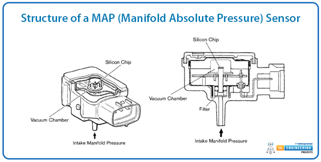
The Manifold Absolute Pressure sensor works as a vital microelectronic system to monitor engine intake manifold pressure. A signal processed by the Engine Control Unit (ECU) adjusts fuel injection and ignition timing using the information gained from manifold pressure assessment. Every part inside the MAP sensor plays a specific role in transforming intake manifold pressure readings into precise electronic signals while maintaining reliable operation.
1. Sensing Element:
The sensing element is at the heart of the MAP sensor, which is responsible for sensing pressure variations within the intake manifold. The element is usually constructed from either:
Piezoelectric material generates a minor electrical charge in response to pressure variations.
A capacitive diaphragm consists of a flexible material that applies transformable capacitance depending on pressure level changes.
The signal output from the sensing element corresponds directly to the pressure changes in the intake manifold using the expansion or contraction of the sensor element.
2. Electronic Circuit Board:
The electronic circuit board takes the raw signal from the sensing element and converts it into a readable form for the ECU. It consists of:
Signal amplifier: Amplifies the weak electrical signal from the sensing element.
Analog-to-digital converter (ADC): Translates the signal to voltage or frequency output.
Temperature compensation circuits: Provide accurate readings irrespective of engine temperature fluctuations.
This circuit board makes sure that the pressure information is accurate and trustworthy under various operating conditions.
3. Vacuum Port:
The vacuum port is the point of connection between the MAP sensor and the intake manifold. The sensor can be mounted:
Directly on the manifold, where it reads pressure directly.
By a vacuum hose, where it is read remotely for pressure.
The vacuum port enables the sensor to sense manifold pressure changes in real time, allowing the ECU to make instant adjustments.
4. Electrical Connector:
The electrical connector connects the MAP sensor to the ECU. Most MAP sensors come with a three-wire setup:
Power supply (5V from ECU): Supplies voltage for the sensor to work.
Ground: Grounds the electrical circuit.
Signal output: Outputs the processed pressure a voltage or frequency signal from ECU.
This link provides reliable communication between the MAP sensor and the ECU.
5. Protective Housing:
The MAP sensor is housed in a robust plastic or metal housing to safeguard it from:
Heat and hot temperatures within the engine compartment.
Vibration and mechanical shock when the vehicle is in use.
Moisture, vapors of fuel, and dust can compromise sensor performance.
This rugged enclosure will safeguard sensor ruggedness and reliability.
Types of MAP:
MAP sensors are of different types based on their output signal, pressure measurement method, and application. The vehicle's engine configuration, fuel injection system, and naturally aspirated or turbocharged status decide the type of MAP sensor used in a vehicle. The following are the main types of MAP sensors.
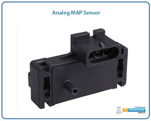
1. Analog MAP Sensor:
An analog MAP sensor produces a changing voltage signal as a function of manifold pressure. The output voltage is typically between 0.5V (high vacuum, low pressure) and 4.5V (low vacuum, high pressure).
How It Works:
During idling or deceleration, the vacuum is high, and the sensor produces a low voltage.
During acceleration or heavy load, the vacuum is low, and the sensor produces a higher voltage.
The ECU converts these voltage variations to modify the fuel injection and ignition timing.
Typical Applications:
Utilized in naturally aspirated engines.
Typical of older fuel-injected cars.
2. Digital MAP Sensor:
A digital MAP sensor gives an output based on frequency rather than voltage. The frequency of the signal varies with manifold pressure, normally between 30 Hz and 150 Hz.
How It Works:
Under low pressure (high vacuum), the sensor generates a low-frequency signal.
At high pressure (low vacuum), the sensor outputs a high-frequency signal.
The ECU interprets these frequency variations to modify fuel injection.
Common Applications:
Applied in contemporary electronic fuel injection (EFI) systems.
Installed in newer cars with sophisticated engine control systems.
3. Absolute MAP Sensor:
An absolute MAP sensor reads pressure about a perfect vacuum (0 psi) rather than atmospheric pressure. This is helpful in engines where pressure fluctuates at extremes, like turbocharged or supercharged engines.
How It Works:
Reads manifold pressure in absolute terms (psi or kPa).
Gives precise readings at high altitudes, where atmospheric pressure varies.
Common Applications:
Employed in turbocharged and supercharged engines.
Installed in vehicles working in high-altitude regions.
4. Speed-Density MAP Sensor:
A speed-density MAP sensor combines with the engine speed (RPM) sensor to determine air density and fuel delivery. It doesn't depend on a Mass Airflow (MAF) sensor and thus is perfect for vehicles with none.
How It Works:
Employ MAP sensor inputs and RPM readings to approximate air intake.
Assists the ECU in figuring out the appropriate fuel mix without the requirement for an MAF sensor.
Popular Applications:
Used in speed-density fuel injection engines.
Installed in racing and high-performance engines where it is not easy to measure airflow.
Comparison Table of MAP Sensor Types:
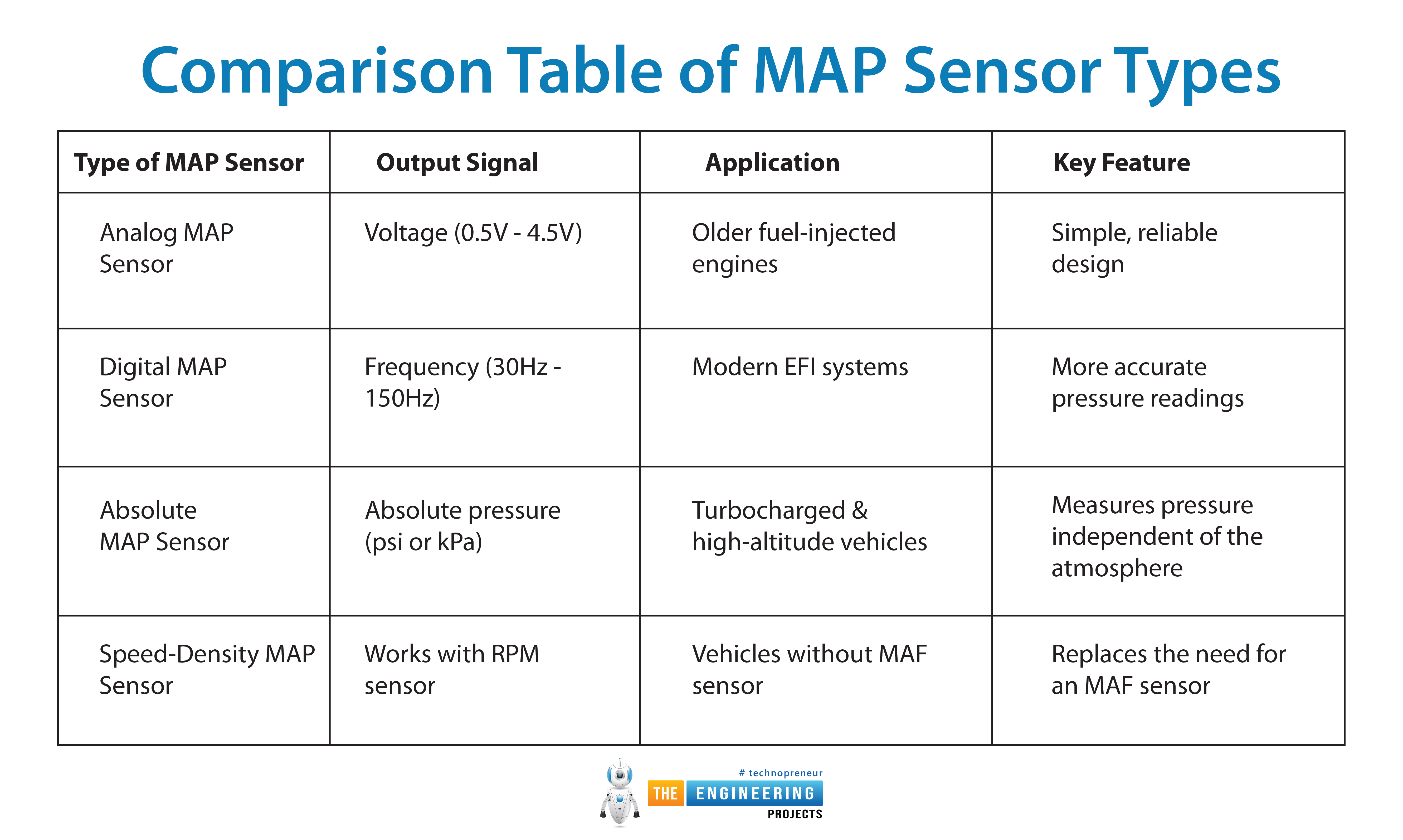
Type of MAP Sensor |
Output Signal |
Application |
Key Feature |
Analog MAP Sensor |
Voltage (0.5V - 4.5V) |
Older fuel-injected engines |
Simple, reliable design |
Digital MAP Sensor |
Frequency (30Hz - 150Hz) |
Modern EFI systems |
More accurate pressure readings |
Absolute MAP Sensor |
Absolute pressure (psi or kPa) |
Turbocharged & high-altitude vehicles |
Measures pressure independent of the atmosphere |
Speed-Density MAP Sensor |
Works with the RPM sensor |
Vehicles without an MAF sensor |
Replaces the need for an MAF sensor |
Conclusion:
The Manifold Absolute Pressure (MAP) sensor is one of the vital parts of the contemporary engine management system. The sensor assists the Engine Control Unit (ECU) to modify fuel injection and ignition timing by making available precise manifold pressure measurements. Various MAP sensors, such as analog, digital, absolute, and speed-density sensors are utilized depending on the design and performance requirements of the engine.
Analog MAP sensors are used in older models, while digital MAP sensors provide greater accuracy for newer engines. Absolute MAP sensors are used by turbocharged and high-altitude vehicles, and speed-density MAP sensors substitute the Mass Airflow (MAF) sensor requirement.
Selecting the proper MAP sensor guarantees optimum fuel combustion, improved engine performance, and lower emissions. With growing automotive technology, the MAP sensor is also evolving in accordance, contributing significantly to improved fuel efficiency and vehicle reliability. The role of MAP sensors in both traditional and high-performance engines cannot be underestimated.


 Embedded Sensors
 xeohacker
 0 Comments


