Hello friends, I hope you all are doing great. Today, I am going to share the new A4988 / DRV8825 Stepper Driver Library for Proteus V1.0. These two tiny boards, the green A4988 and the purple DRV8825, drive the stepper motors of almost every 3D printer, laser engraver and hobby CNC machine. Two Arduino pins, STEP and DIR, are all they need, and they split every step of the motor into as many as 32 microsteps for a smooth, quiet motion. Now they are ready for your Proteus simulations, together with a NEMA 17 stepper motor that carries a dial on its shaft, so you can watch every step.
Behind the boards sits our own model of the A4988 and the DRV8825: the translator with its microstep tables, EN, SLEEP and RESET, the current limit set by VREF, and a chopper that pushes the coil currents only as fast as the motor supply allows. The motor is a model too, with the coils, the torque, the detent, the inertia and the back-EMF of a real NEMA 17, so it follows the microsteps, slows down when the supply is too low and loses steps when you load it too much. You get five devices: each board as a Simple device with a live STATUS panel and as an Advance device with a pop-up window and three test tools, plus the NEMA 17. The demo runs on our Arduino UNO V4.0 with the AccelStepper library.
NOTICE: a stepper is only interesting in a simulator if it can go wrong the way a real one does. So we did not draw a dial that simply follows the step count: the rotor is pulled by the coil currents, it rings a little after each full step, it needs a higher voltage to go faster, and under a heavy load it slips and the Arduino never knows. It took our team a lot of hard work. Your feedback is the fuel that keeps us going, so please tell us what you think in the comments below or in the Motor Driver board of our forum. And if our free libraries help you, you can buy us a coffee. So, let's get started with the A4988 / DRV8825 Stepper Driver Library for Proteus V1.0:
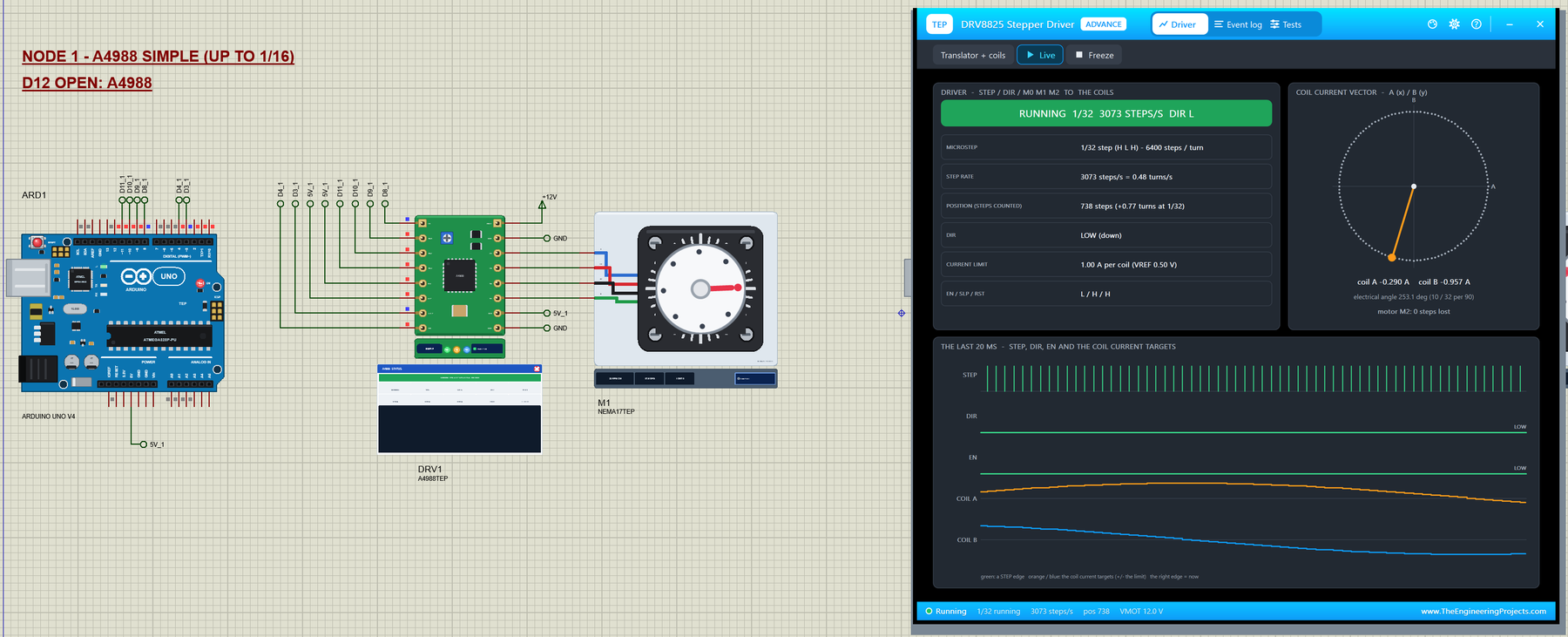
What is a Stepper Motor Driver?
A stepper motor turns in fixed steps instead of spinning freely. The common hybrid stepper has two coils, A and B, and a toothed rotor with 50 teeth. When a current flows in a coil, the rotor teeth line up with the stator teeth that the current magnetizes. Switch the currents in the right order, A, then B, then A reversed, then B reversed, and the rotor moves one tooth for every four steps: 50 teeth times 4 gives the famous 200 steps per turn, 1.8 degrees each. Stop switching and the rotor stays where it is, held by the current.
Driving those coils directly takes two H-bridges, a current limit and a table of what to switch when. A stepper driver chip does all of that. Your microcontroller only gives it two signals: STEP, where every rising edge moves the motor one step, and DIR, which chooses the direction. The chip keeps the position in its translator and regulates the coil currents itself. That is why one Arduino can run several steppers with two pins each.
| A4988 (green board) | DRV8825 (purple board) | |
|---|---|---|
| Maker | Allegro MicroSystems | Texas Instruments |
| Motor supply VMOT | 8 - 35 V | 8.2 - 45 V |
| Current per coil | about 1 A without a heatsink, 2 A with one | about 1.5 A without a heatsink, 2.2 A with one |
| Microsteps | full, 1/2, 1/4, 1/8, 1/16 | full, 1/2, 1/4, 1/8, 1/16, 1/32 |
| Logic supply | VDD, 3 - 5.5 V | its own 3.3 V regulator (no VDD pin) |
| Shortest STEP pulse | 1 us HIGH and LOW | 1.9 us HIGH and LOW |
| Current limit | VREF / 0.544 (0.068 ohm sense resistors) | VREF x 2 (0.1 ohm sense resistors) |
| Extra pin | VDD | FAULT (FLT) |
| Devices in this library | A4988TEP (Simple), A4988ADVTEP (Advance) | DRV8825TEP (Simple), DRV8825ADVTEP (Advance) |
Both boards have the same size, 0.6 x 0.8 inch, and the same 16 pins in two rows, so they plug into the same sockets of a 3D printer board. On the left side are the control pins EN, MS1 (M0), MS2 (M1), MS3 (M2), RST, SLP, STEP and DIR; on the right side VMOT, GND, the four coil pins and VDD (on the DRV8825: FLT) and GND.
Microstepping
A full step moves the current from one coil to the next in one jump, so the rotor jumps 1.8 degrees and rings. Microstepping shares the current between the two coils along a sine and a cosine curve, so the magnetic field, and the rotor with it, moves in many small steps instead. Three pins choose the step size:
| MS1 / M0 | MS2 / M1 | MS3 / M2 | A4988 | DRV8825 | Steps per turn |
|---|---|---|---|---|---|
| L | L | L | Full step | Full step | 200 |
| H | L | L | 1/2 | 1/2 | 400 |
| L | H | L | 1/4 | 1/4 | 800 |
| H | H | L | 1/8 | 1/8 | 1600 |
| H | H | H | 1/16 | 1/32 | 3200 / 6400 |
| L | L | H | not in the table | 1/16 | 3200 |
| H | L | H | not in the table | 1/32 | 6400 |
All the microstep pins have pull-down resistors on the boards, so pins left open mean full step. Note that the same pin pattern HHH gives 1/16 on the A4988 but 1/32 on the DRV8825: a sketch written for one board turns the motor half as far on the other. Our demo reads which board it drives from one pin and sets the pins for it.
EN, SLEEP and RESET
EN (ENABLE) is active LOW: LOW switches the outputs on, HIGH switches them off and the shaft turns freely. Here is a detail that catches many people: with EN HIGH the translator still counts the STEP pulses, so the motor misses them and is out of place when EN goes LOW again. SLP (SLEEP) LOW puts the chip to sleep and ignores the inputs, and RST (RESET) LOW sends the translator back home. On the A4988 board RST is floating, so the usual trick is a wire from RST to SLP; on the DRV8825 board both have pull-downs and must be driven HIGH. In our demo both go to 5V.
Setting the Current Limit
A stepper is usually driven with a supply far above its coil voltage: our 1.5 ohm motor would need only 1.5 V for 1 A, but it gets 12 V. The chip makes this work by chopping: it switches the full supply onto the coil until the current reaches the limit, then lets it decay, thousands of times a second. The limit is set with the little trimpot on the board, which gives a reference voltage VREF. On the A4988 board with 0.068 ohm sense resistors the limit is VREF / 0.544, so 0.54 V gives 1 A; on the DRV8825 board it is VREF x 2, so 0.50 V gives 1 A. In this library VREF is a property of the part.
The NEMA 17 Stepper Motor
NEMA 17 only names the size of the front plate, 1.7 inch or 42.3 mm square, but most NEMA 17 motors of printers and CNC machines are very similar. Our model follows the typical 1.7 A motor:
| NEMA 17 (the model) | |
|---|---|
| Steps | 200 per turn, 1.8 deg each (50 rotor teeth) |
| Coils | 1.5 ohm and 2.8 mH each, rated 1.7 A |
| Holding torque | 40 N.cm at 1.7 A in both coils (16.6 N.cm at the demo's 1 A) |
| Detent torque | 2.2 N.cm (the notchy feel without current) |
| Wires | A+ black, A- green, B+ red, B- blue |
| On the schematic | a dial on the shaft that turns at the real angle; RPM, angle, LOST and the LOAD button |
What's New in A4988 / DRV8825 Stepper Driver Library for Proteus V1.0
- Two real boards: the green A4988 and the purple DRV8825 carrier with the chip, the current-limit trimpot, the sense resistors and the 16 pins in the real order, drawn at twice their real size.
- The translators: STEP and DIR, the microstep tables up to 1/16 and 1/32, EN, SLEEP and RESET with the boards' pull resistors.
- The current limit from VREF, with the formulas of the real boards.
- A chopper with real limits: the coil currents rise only as fast as VMOT allows against the inductance and the back-EMF, and fall with the chips' mixed decay, so the torque drops at speed.
- A NEMA 17 with a dial that turns at the simulated angle, with RPM, angle, the steps LOST and a LOAD button that brakes it.
- Lost steps: overload the motor and it slips; the driver and the motor both report it.
- Three test tools on the Advance devices: Microstep table, STEP timing and Power.
- A two-node demo on our Arduino UNO V4.0 with AccelStepper: a tour through every microstep mode and quarter turns, with serial commands.
- A compact package: about 1.31 MB, without the C++ source code of the model.
Five Devices: Simple, Advance and the Motor
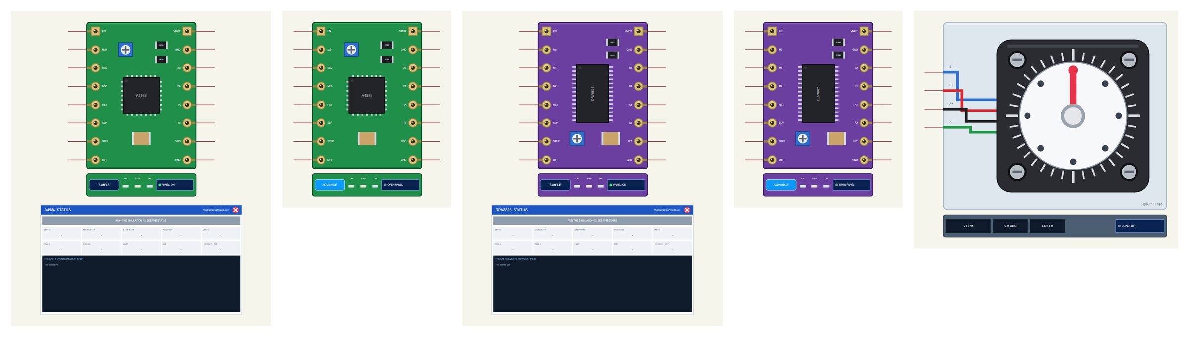
| Simple | Advance | Motor | |
|---|---|---|---|
| Devices | A4988TEP, DRV8825TEP | A4988ADVTEP, DRV8825ADVTEP | NEMA17TEP |
| On the schematic | The board + the STATUS panel | The board only | The motor with its dial |
| Status | Banner, 10 readouts, the last 6 events | A pop-up: Driver, Event log, Tests | RPM, angle, LOST |
| Interaction | PANEL button | OPEN PANEL button | LOAD button, a click on the dial |
Download A4988 / DRV8825 Stepper Driver Library for Proteus
Click the button below to download A4988-DRV8825-Stepper-Driver-Library-for-Proteus-v1.0.zip (about 1.31 MB, without the C++ source code of the model):
A4988 / DRV8825 Stepper Driver Library for Proteus V1.0- README.txt: the devices, installation, the demo, wiring, the test tools and real hardware.
- Proteus Library Files:
TEPSTEPPER.LIBandArduinoV4TEP.LIBfrom our Arduino Library for Proteus V4.0. - Proteus Model Files:
TEPSTEPPER.DLLandTEPARDUINO.DLL. - Proteus Simulation:
A4988-DRV8825-Stepper-ArduinoUnoV4.pdsprj,Stepper_Demo.hexand copies of the two DLLs. - Arduino Code:
Stepper_Demo.inoand the AccelStepper library it uses (GPL-3.0, unmodified, with its licence).
No Proteus yet? Read How to Download and Install Proteus 7 and 8. New to libraries? Follow How to Install a New Library in Proteus.
How to Install A4988 / DRV8825 Stepper Driver Library for Proteus
- Close Proteus and extract the whole zip file, for example to your Desktop.
- Copy the two files from Proteus Library Files into the LIBRARY folder of Proteus (usually
C:\Program Files (x86)\Labcenter Electronics\Proteus 8 Professional\LIBRARY). - Copy
TEPSTEPPER.DLLandTEPARDUINO.DLLfrom Proteus Model Files into the MODELS folder. - Delete
TEPSTEPPER.IDXfrom the LIBRARY folder if it is there. - Start Proteus, press P and search for A4988, DRV8825 or NEMA.
Tip: keep the Proteus Simulation folder together, because the project needs its .hex file and the DLLs beside it. The library is tested in Proteus 8.5; Proteus 7 is not supported. For DC motors, see our L9110S, TB6612FNG and BTS7960 motor driver libraries.
The A4988 and DRV8825 Boards in Proteus
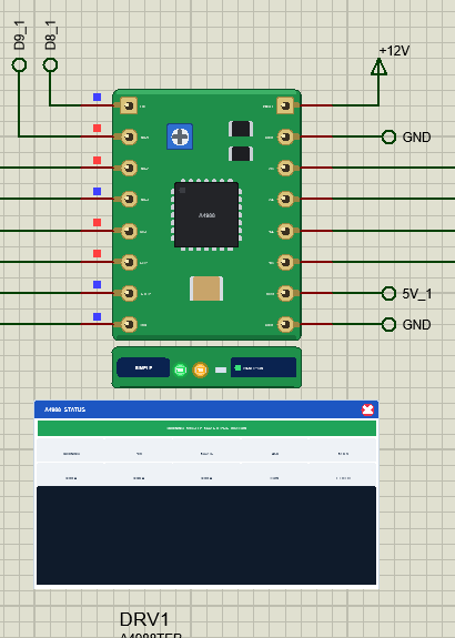
The boards look like the real carriers: the chip in the middle, the blue current-limit trimpot, the two black sense resistors and the 16 gold pads, with the pins in the order of the real boards. On the green A4988 the trimpot sits at the top, on the purple DRV8825 at the bottom, just as on the boards you buy.
Under each board is the TEP strip. The ON LED is green while VMOT (and on the A4988 the logic supply VDD) is in range, the STEP LED flashes with the steps and the DIR LED shows DIR HIGH. The strip, its LEDs and the panels are TEP additions; a real carrier has none of them.
The Simple devices add the STATUS panel. Its banner says what the driver does, for example "RUNNING 1/16 STEP 3200 STEPS/S DIR HIGH", or shows HOLDING, DISABLED, SLEEP, RESET, NO MOTOR SUPPLY or the latest warning. Ten readouts follow: the state, the microstep mode, the step rate, the position, VMOT, the two coil currents, the current limit, DIR and EN / SLP / RST. At the bottom are the last six events. The red X closes the panel, and the PANEL button on the strip opens it again.
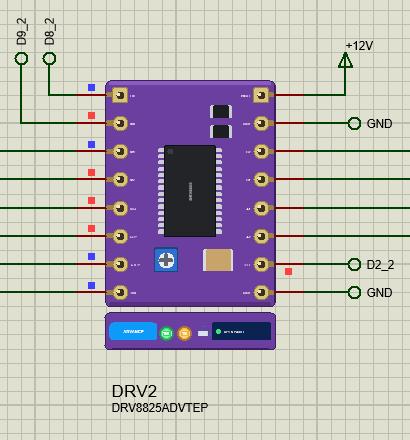
The Advance devices keep the schematic clean: only the board and its strip. Their live data opens in a pop-up window at Run, and the OPEN PANEL button brings the window back if you close it. The DRV8825's FLT pin follows SLP through the board's 10 kohm resistor, so it reads HIGH while the chip is awake.
The NEMA 17 in Proteus
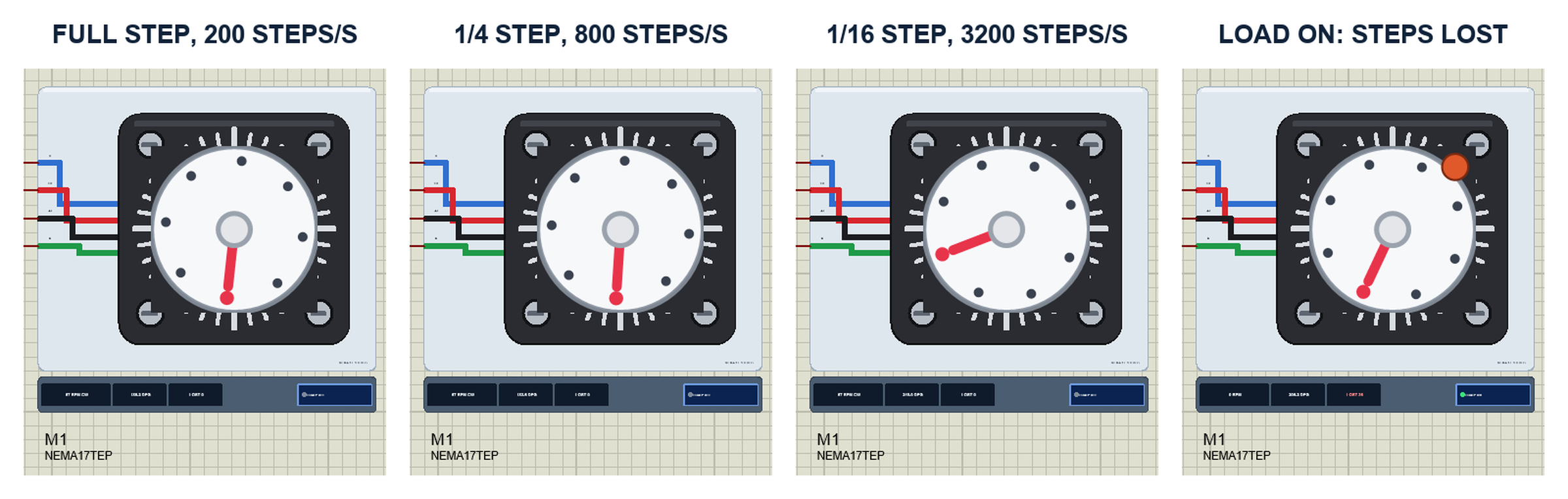
The motor is drawn from its shaft end: the clear mounting plate, the black square flange with its four screws, the round boss with a degree scale and a white dial on the shaft with a red pointer. The four wires leave on the left in the colours of a real NEMA 17. While the simulation runs, the dial turns at the real angle of the rotor, and when it turns fast it blurs. The strip under it shows the speed with its direction, the angle of the dial and LOST, the steps the rotor fell behind.
The dial is not a counter of STEP pulses. It follows the rotor of the model, and the rotor follows the magnetic field of the two coil currents. So at full step you can see it jump 1.8 degrees and ring for a moment, while at 1/16 step it glides. In the run, both motors went through every microstep mode and four quarter turns and ended each turn exactly on 0, 90, 180 and 270 degrees: 0 steps lost in 26 s of simulation.
The LOAD Button and Lost Steps
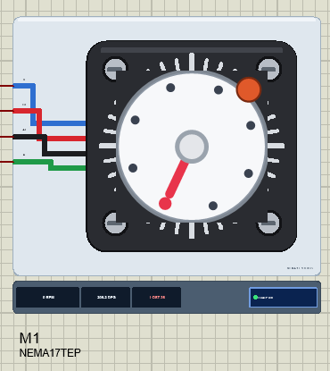
Click LOAD under the motor, or click its dial, and a brake shoe presses on the rim with 20 N.cm. At the demo's current limit of 1 A the motor gives only 16.6 N.cm, so it cannot turn: the field moves on, the rotor stays, and every time the field gets four full steps ahead the rotor slips back by one tooth. The model counts those slips as LOST steps and writes them to the log, for example "M1 lost 32 full steps (36 in all) - the load is above the motor's torque". The property LOAD adds a constant load in N.cm for the whole run.
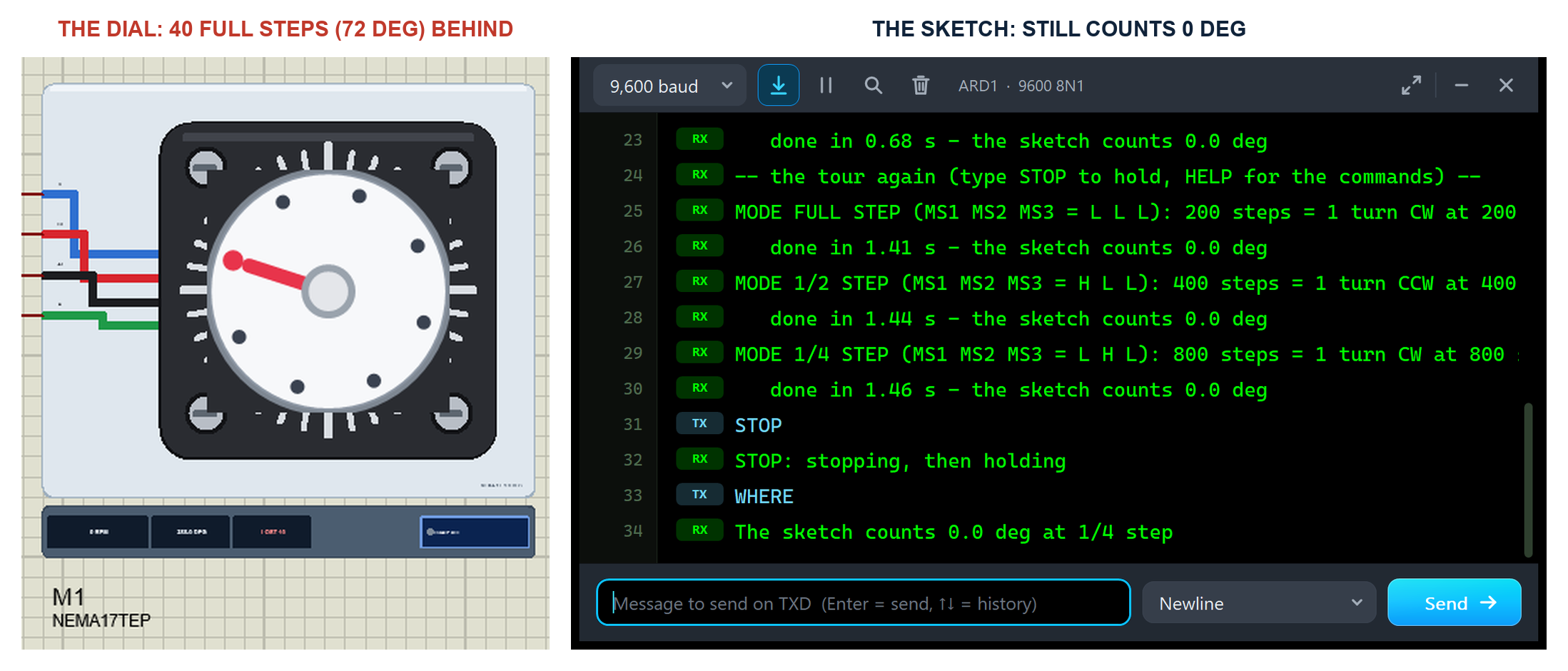
This is the most important lesson of a stepper, and the reason 3D printers have end stops. In the run, LOAD was pressed before the quarter turn to 270 degrees and released after it. The motor lost 40 full steps in all. The sketch, which only counts its own STEP pulses, went on with the tour and reported 0.0 degrees after the next turn, while the dial stood at 288 degrees, exactly 72 degrees (40 x 1.8) behind. A stepper runs open loop: if it slips, nothing tells the controller, unless you add a sensor.
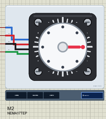
When the motor does not slip, it is precise: after the commands M 2 and GOTO 90 on node 2, the 100 half steps turned motor M2 from 0 to exactly 90.00 degrees.
The Demo Circuit
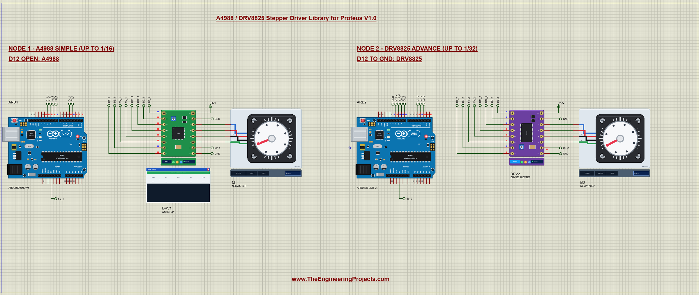
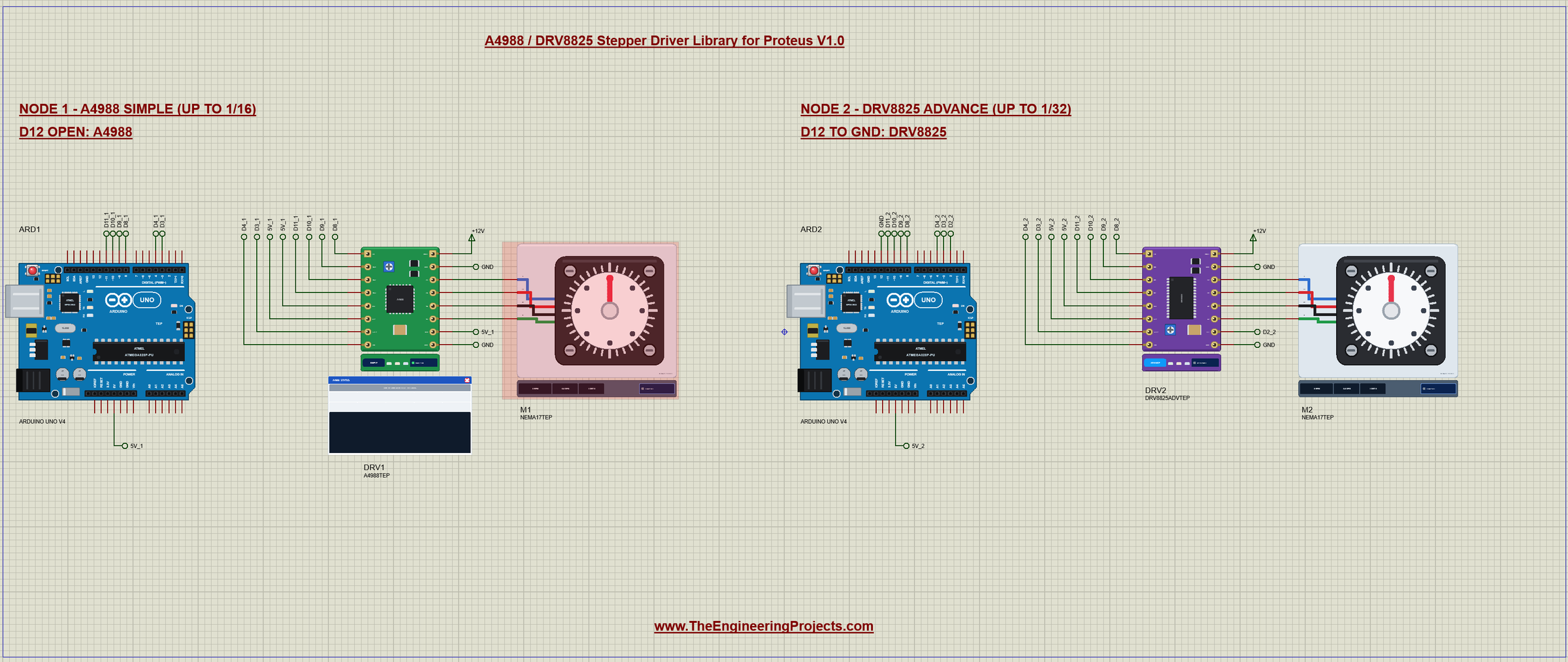
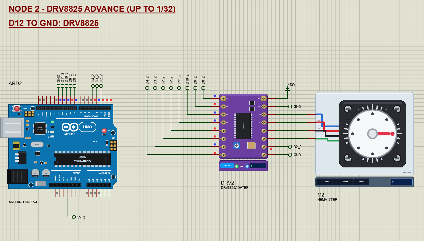
The demo project has two nodes. Each one is an Arduino UNO V4.0 from our Arduino UNO Library for Proteus V4.0, one driver board and one NEMA 17. Both UNOs run the same Stepper_Demo.hex, and the D12 pin tells the sketch which board it drives: node 1 leaves D12 open and drives the A4988 Simple device, node 2 ties D12 to GND and drives the DRV8825 Advance device. VMOT of both boards comes from a +12V power terminal, which Proteus turns into a 12 V supply.
Wiring
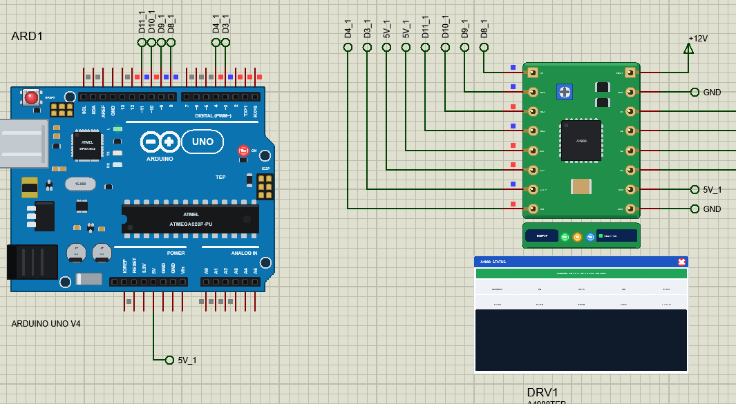
| Board | Arduino UNO | Note |
|---|---|---|
| STEP | D3 | one rising edge = one (micro)step |
| DIR | D4 | HIGH = clockwise on the dial |
| EN | D8 | LOW = the outputs on |
| MS1 / M0, MS2 / M1, MS3 / M2 | D9, D10, D11 | the microstep mode |
| RST, SLP | 5V | both HIGH: awake and running |
| VDD (A4988) | 5V | the A4988's logic supply |
| FLT (DRV8825) | D2 | HIGH = no fault |
| VMOT, GND | 12 V supply | GND common with the Arduino |
| 2B 2A 1A 1B / B2 B1 A1 A2 | motor | to the NEMA 17's B- B+ A+ A- |
In Proteus every control pin reaches its UNO through a wire with a net label: D3_1, D4_1, D8_1, D9_1, D10_1, D11_1 and 5V_1 for node 1, the same with _2 for node 2, D2_2 for the FAULT pin, and GND. The coil pins of the board sit in the same rows as the motor's wires, so they run straight across. To reverse a motor, swap the two wires of one coil. The serial monitor needs no wires at all, because it is built into the UNO V4.0.
Node 1: the A4988 Tour
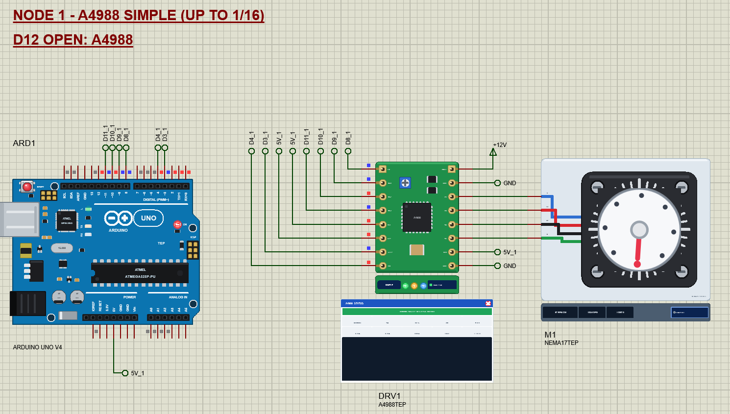
The sketch takes the motor on a tour. It turns one full turn in each microstep mode, full step clockwise, 1/2 step back, 1/4 step clockwise again and so on up to 1/16 step on the A4988, always at about one turn per second: 200 steps/s at full step, 3200 steps/s at 1/16. AccelStepper accelerates to that speed in half a second and slows down at the end. Then come four quarter turns at the finest step with a short stop between them, and the tour starts again.
Node 2: the DRV8825 at 1/32 Step
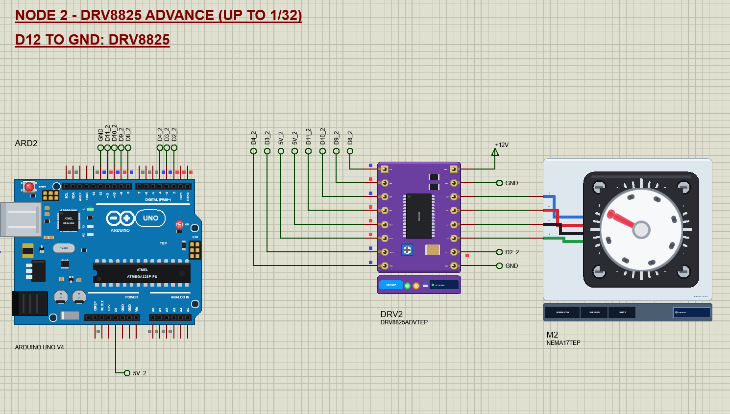
Node 2 runs the same tour on the DRV8825, which adds a sixth mode, 1/32 step. One turn now takes 6400 steps, and since AccelStepper makes about 3200 steps per second on a 16 MHz UNO, the 1/32 turn takes 2.56 s. That is the price of very fine microsteps: you need a fast step source for speed.
The Arduino Code
The demo uses the popular AccelStepper library by Mike McCauley, which makes the STEP pulses with smooth acceleration and deceleration. It is in the zip under Arduino Code, or in the Library Manager of the Arduino IDE. New to Arduino? Start with Arduino Tutorial for Beginners and Introduction to Arduino UNO. The pins and the stepper object come first:
const uint8_t STEP_PIN = 3, DIR_PIN = 4, EN_PIN = 8, CHIP_PIN = 12, FAULT_PIN = 2;
const uint8_t MS_PIN[3] = {9, 10, 11};
const long MAX_RATE = 3200;                  // steps/s: about what AccelStepper does on a 16 MHz UNO

AccelStepper motor(AccelStepper::DRIVER, STEP_PIN, DIR_PIN);
AccelStepper::DRIVER is the mode for STEP / DIR driver boards. In setup() the sketch switches the outputs on with EN LOW and makes the STEP pulses at least 2 us long, because the DRV8825 needs 1.9 us:
  pinMode(EN_PIN, OUTPUT);
  digitalWrite(EN_PIN, LOW);                 // EN is active LOW: the outputs on
  for (uint8_t k = 0; k < 3; ++k) pinMode(MS_PIN[k], OUTPUT);
  motor.setMinPulseWidth(2);                 // the DRV8825 needs 1.9 us HIGH and LOW (the A4988 1 us)
The microstep pins differ between the two chips, so one function gives the pin pattern for each mode. Note the 1/16 line: HHH on the A4988, but LLH on the DRV8825:
uint8_t msBits(int m) {
  switch (m) {
    case 1: return 0b000;
    case 2: return 0b001;
    case 4: return 0b010;
    case 8: return 0b011;
    case 16: return drv8825 ? 0b100 : 0b111;
    default: return 0b101;                   // 1/32 (DRV8825)
  }
}
Changing the mode writes the three pins and sets the speed to one turn per second, as far as the UNO keeps up, with full speed reached in half a second:
void setMicro(int m) {
  micro = m;
  const uint8_t b = msBits(m);
  for (uint8_t k = 0; k < 3; ++k) digitalWrite(MS_PIN[k], (b >> k) & 1 ? HIGH : LOW);
  motor.setCurrentPosition(0);
  const long rate = min(200L * m, MAX_RATE);  // one turn per second, as far as the UNO keeps up
  motor.setMaxSpeed(rate);
  motor.setAcceleration(rate * 2);           // full speed in half a second
}
A move is relative: motor.move() sets the target and motor.run() in the loop makes the steps. When a move ends, the sketch adds the steps to its idea of the angle. This is the open-loop count that the LOAD button proves wrong:
void startMove(long steps) {
  moveStart = millis();
  moving = true;
  motor.setCurrentPosition(0);
  motor.move(steps);
}
posQ += motor.currentPosition() * (maxM / micro); // what was stepped (a STOP ends a move early)A quarter turn is 50 full steps at any microstep mode:
const long steps = 50L * maxM; // 50 full steps = 90 degThe loop reads the serial commands, calls motor.run() as often as it can, and starts the next stage of the tour 0.4 s after a move ends. motor.run() must never wait, or the steps would stutter:
  motor.run();
  if (moving && !motor.isRunning()) { moveDone(); pauseUntil = millis() + 400; }
  if (touring && !moving && (long)(millis() - pauseUntil) >= 0) nextStage();
One AccelStepper detail we hit while testing: stop() decelerates a running motor, but it does nothing to a move that has not made its first step yet. So the sketch cancels such a move itself:
void halt() {
  motor.stop();
  if (motor.speed() == 0) motor.moveTo(motor.currentPosition());
  while (motor.isRunning()) motor.run();
  if (moving) moveDone();
}
The HEX file is in the package. To change the sketch, install AccelStepper, open the sketch in the Arduino IDE and export the compiled binary, as in How to get the HEX file from Arduino. It needs 13,584 bytes of flash and 491 bytes of RAM.
The Advance Pop-Up Window
At Run, the Advance devices open TEP Stepper Driver Advance, with the look of our TEP Serial Monitor Advance for Proteus. It has three tabs, Driver, Event log and Tests, plus Settings and Help behind the gear and question mark icons.
The Driver Page
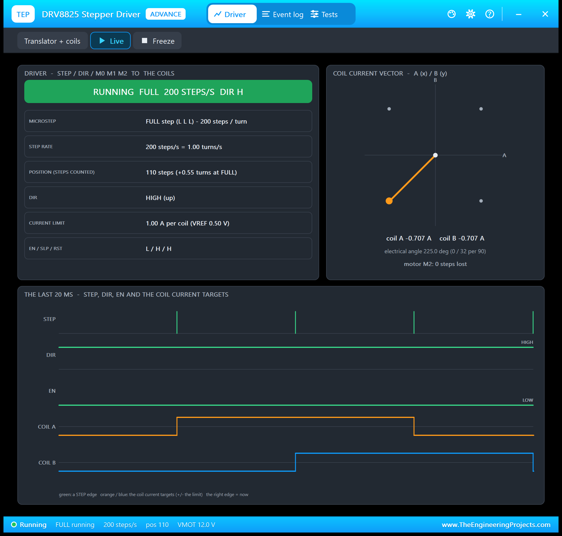
The left card is the translator: the state in big letters, the microstep mode with its pins and the steps per turn, the step rate in steps per second and turns per second, the position, DIR, the current limit and EN / SLP / RST. The right card draws the coil current vector: the current of coil A across and of coil B up. The dots on the circle are the positions of the mode now, and the orange arrow is where the current points. At the bottom are the last 20 ms: the STEP pulses, DIR, EN and the two coil current targets.
At full step the picture is plain: four dots, both coils always at 70.7 % of the limit, and the coil currents are square waves that change sign one after the other.
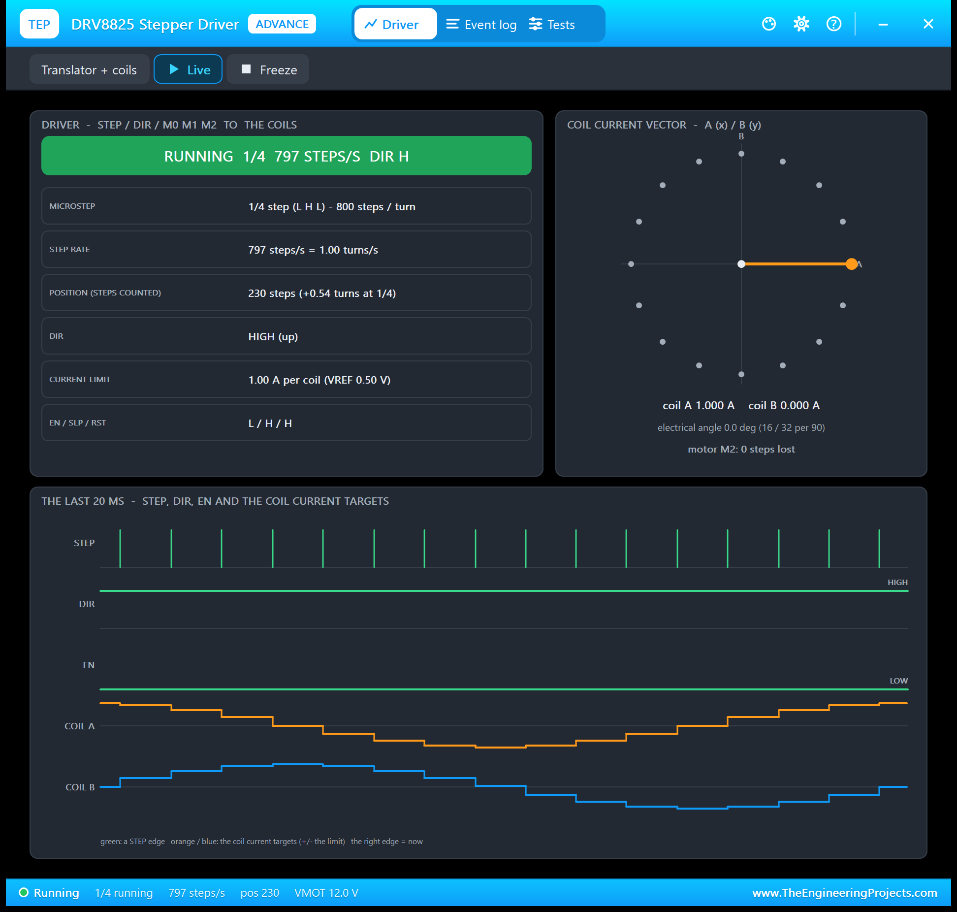
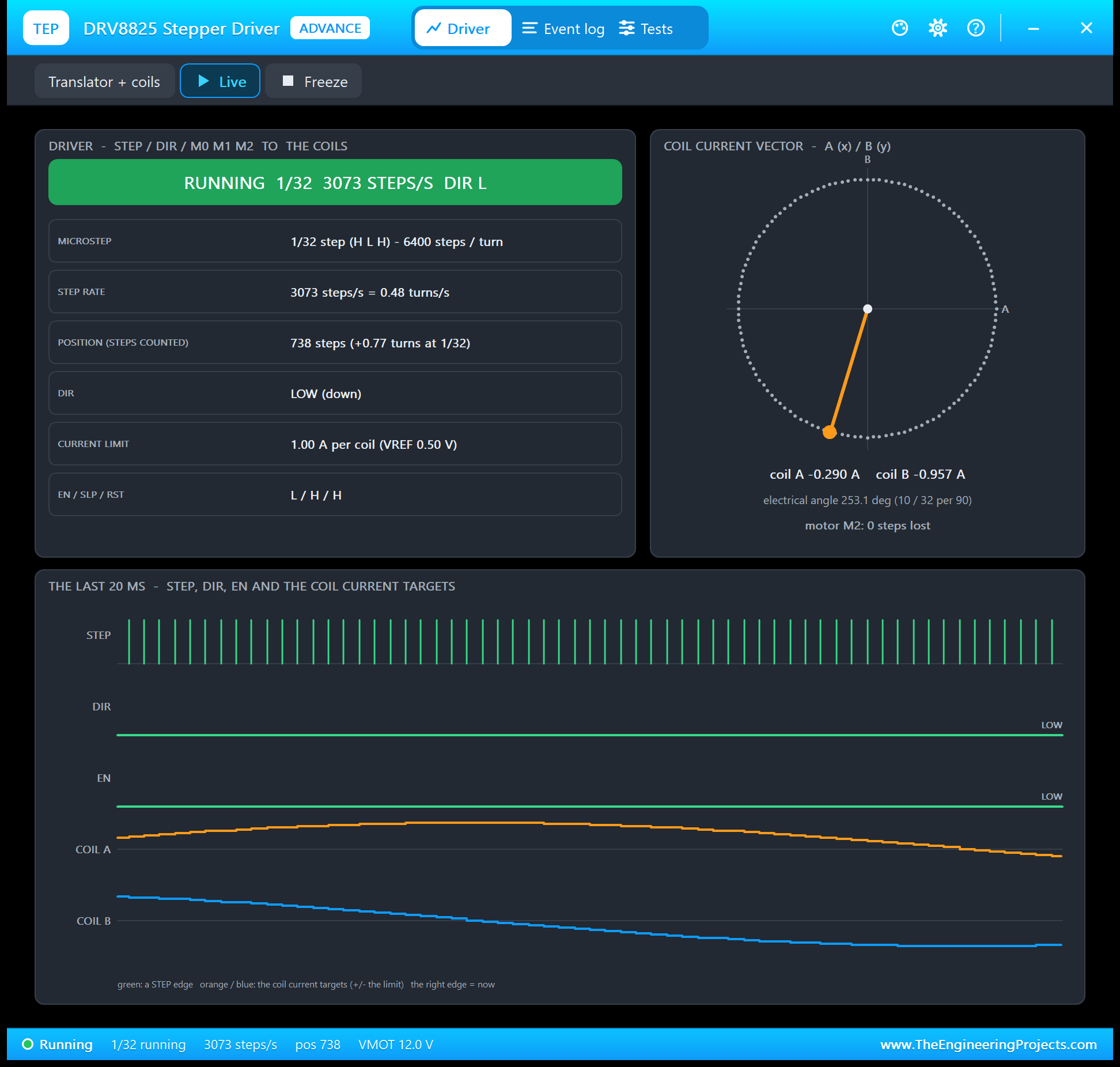
Compare the three screenshots and you see what microstepping is: the same circle, cut into more and more pieces. At 1/32 step the vector walks around 128 positions and the coil currents are almost perfect sine and cosine curves, which is why a microstepped motor runs so quietly. Freeze holds the page for a closer look.
Event Log
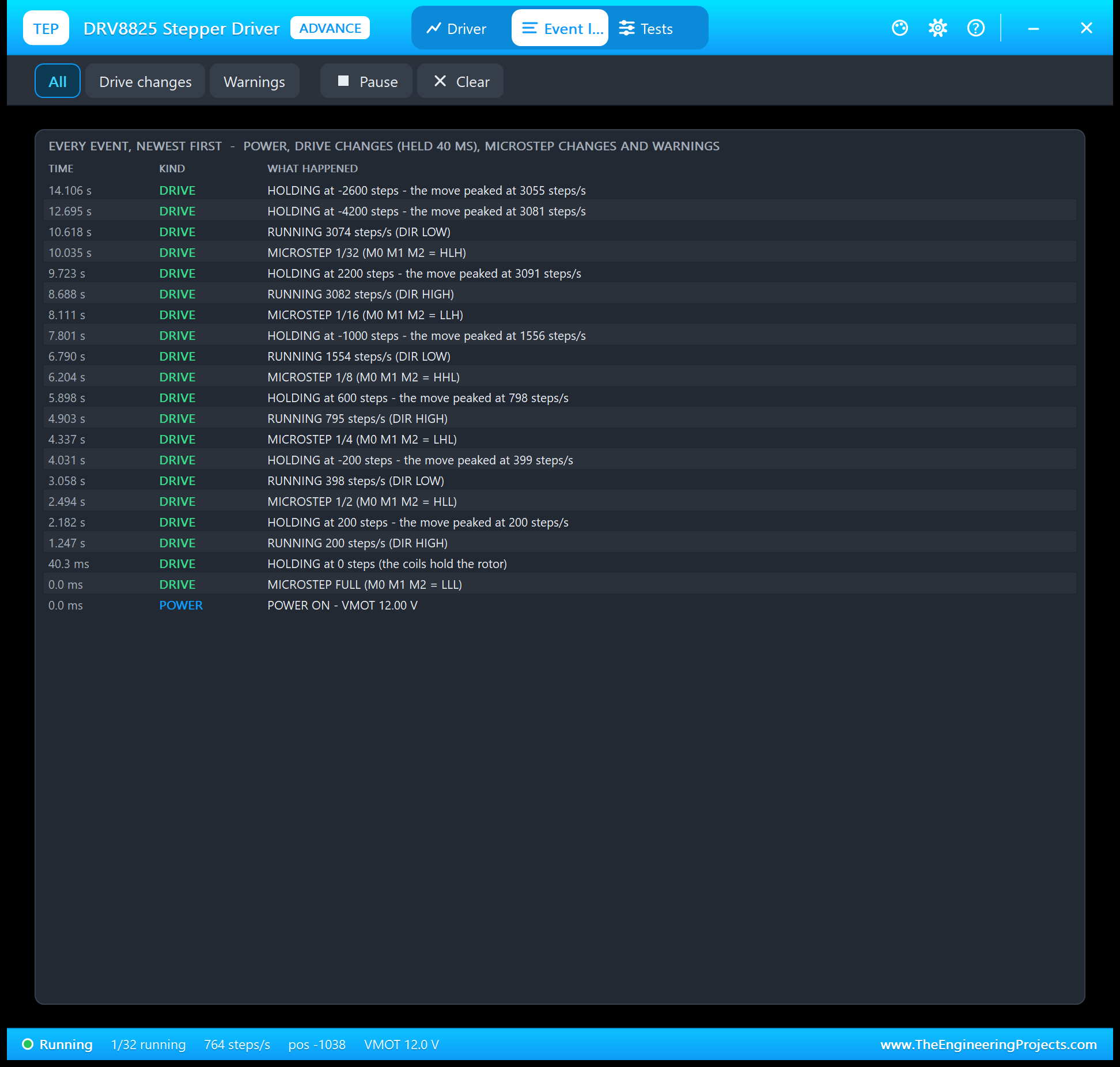
The Event log lists power on and off, every microstep change, the drive changes that held for 40 ms and the warnings. A move writes RUNNING once its speed has been steady for 100 ms, and HOLDING when it ends, with the top speed of the move, for example "HOLDING at 2200 steps - the move peaked at 3091 steps/s". Lost steps of the motor and STEP pulses that are too short appear as warnings. Filter the log by drive changes or warnings, pause it, or clear it.
The Test Tools
The Tests tab holds three tools. Each one reads the driver as the model sees it and gives every row a green, amber or red verdict.
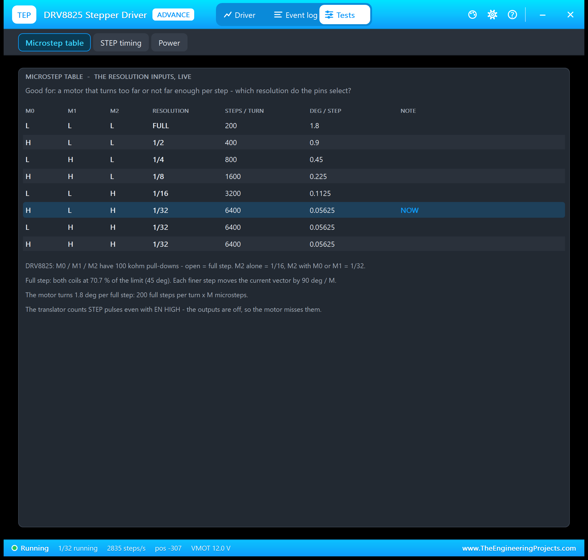
Microstep table is good for a motor that turns too far or not far enough. It lists the chip's table, five rows on the A4988 and eight on the DRV8825, with the steps per turn and the degrees per step, and highlights the row the pins select right now.
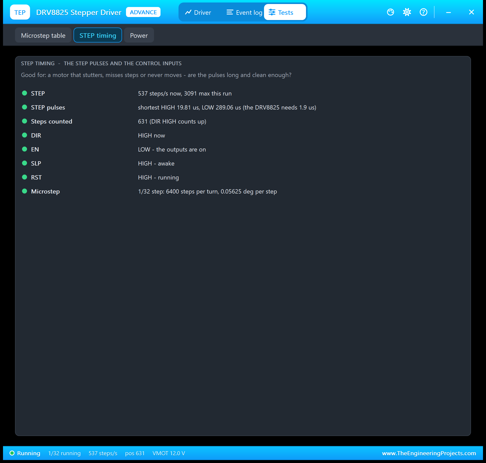
STEP timing is good for a motor that stutters, misses steps or never moves. It shows the step rate and its maximum, the shortest HIGH and LOW time of the STEP pulses against the chip's minimum, the steps counted, and DIR, EN, SLP and RST, with what an open pin reads on that board. In the run the shortest STEP pulse from AccelStepper was 19.81 us, well above the 1.9 us of the DRV8825.
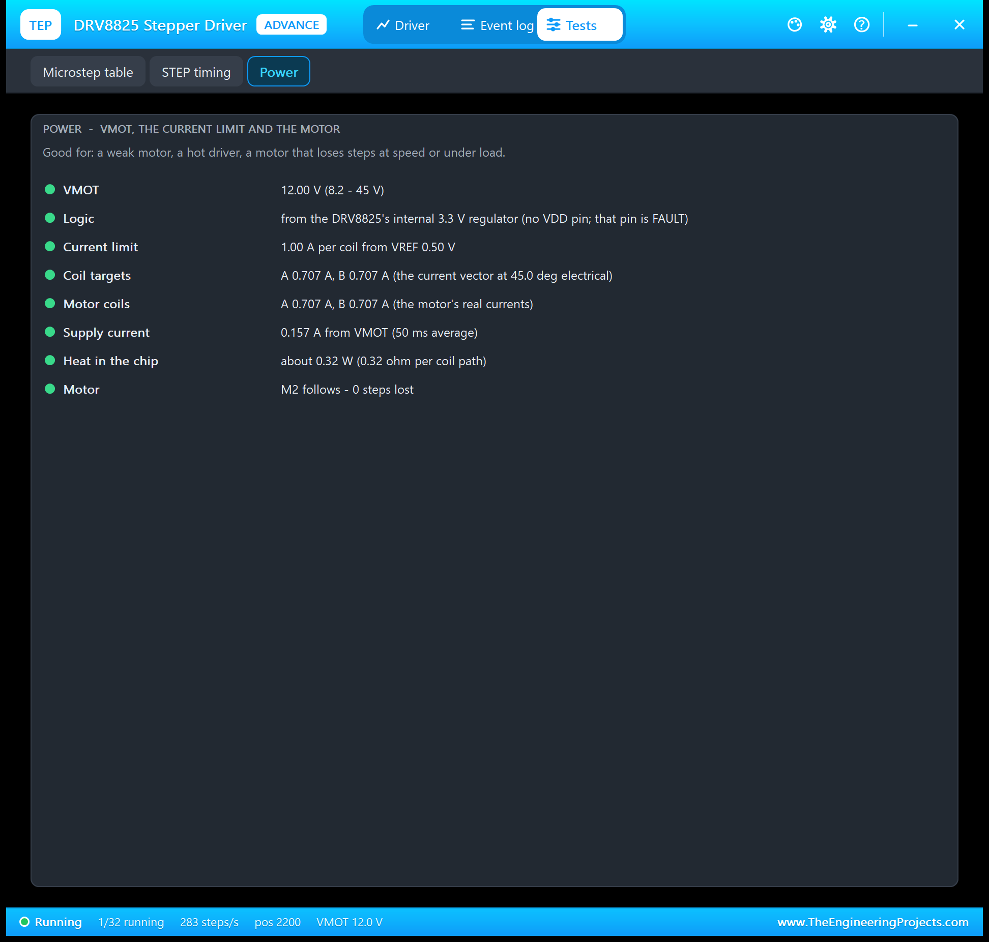
Power is good for a weak motor, a hot driver or a motor that loses steps. It shows VMOT against the chip's range, the logic supply, the current limit from VREF against the board's rating, the coil targets and the motor's real coil currents, the supply current, the heat in the chip and the lost steps. Note the supply current: with 0.707 A in each coil the DRV8825 took only 0.157 A from the 12 V supply. A chopper works like a buck converter, so a stepper driver never needs the coil current from its supply.
The Serial Monitor
Both UNOs have the serial monitor built in, and it opens at Run. The screenshots use its Simple interface. Node 1 starts like this:
TEP A4988 / DRV8825 Stepper Driver - demo (AccelStepper)
Driver: A4988 (D12 open), full to 1/16 step - NEMA 17: 200 full steps per turn
MODE FULL STEP (MS1 MS2 MS3 = L L L): 200 steps = 1 turn CW at 200 steps/s
   done in 1.41 s - the sketch counts 0.0 deg
MODE 1/2 STEP (MS1 MS2 MS3 = H L L): 400 steps = 1 turn CCW at 400 steps/s
   done in 1.44 s - the sketch counts 0.0 deg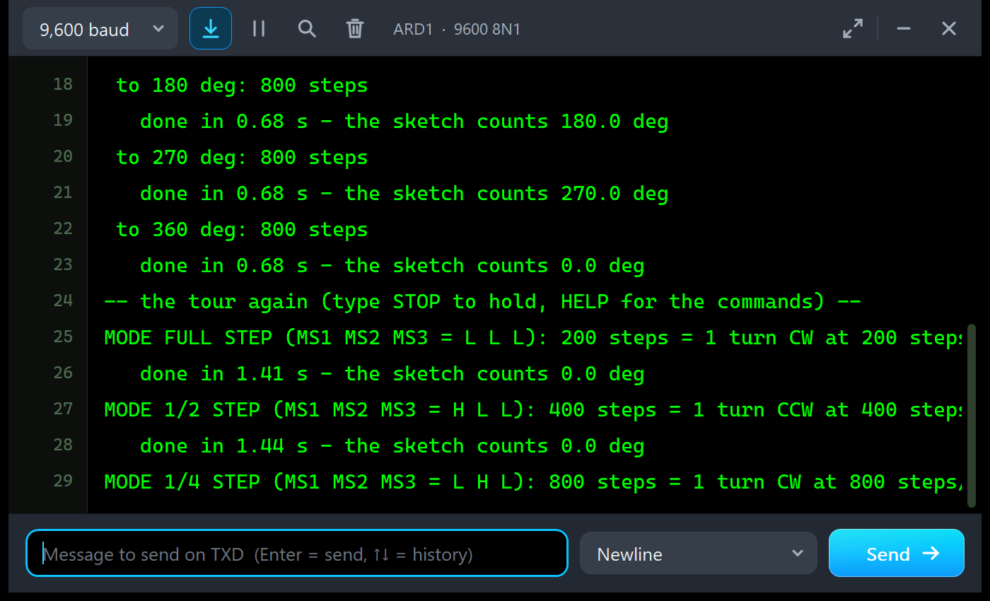
Every move prints its mode, the pin pattern, the number of steps and the speed, and when it ends, the time it took and the angle the sketch believes. Node 2 shows the DRV8825 at 1/32 step:
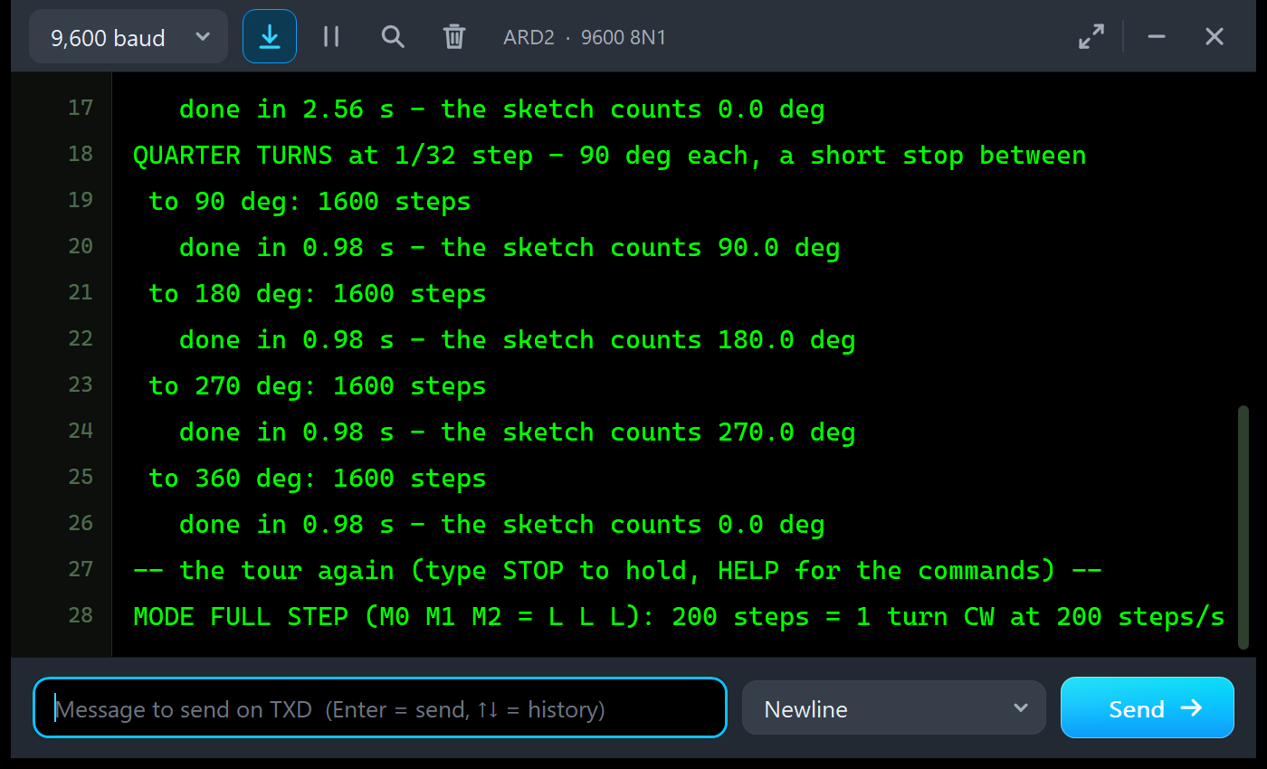
QUARTER TURNS at 1/32 step - 90 deg each, a short stop between
 to 90 deg: 1600 steps
   done in 0.98 s - the sketch counts 90.0 deg
 to 180 deg: 1600 steps
   done in 0.98 s - the sketch counts 180.0 deg
Commands
Type a command in the monitor and press Enter. STOP stops the tour and holds, M 4 chooses a microstep mode, MOVE 200 makes a relative move, GOTO 90 turns to an angle, SPEED and ACCEL change the motion, EN 1 switches the outputs off, WHERE prints the angle the sketch believes, RUN starts the tour again and HELP lists them. In the run, on node 2:
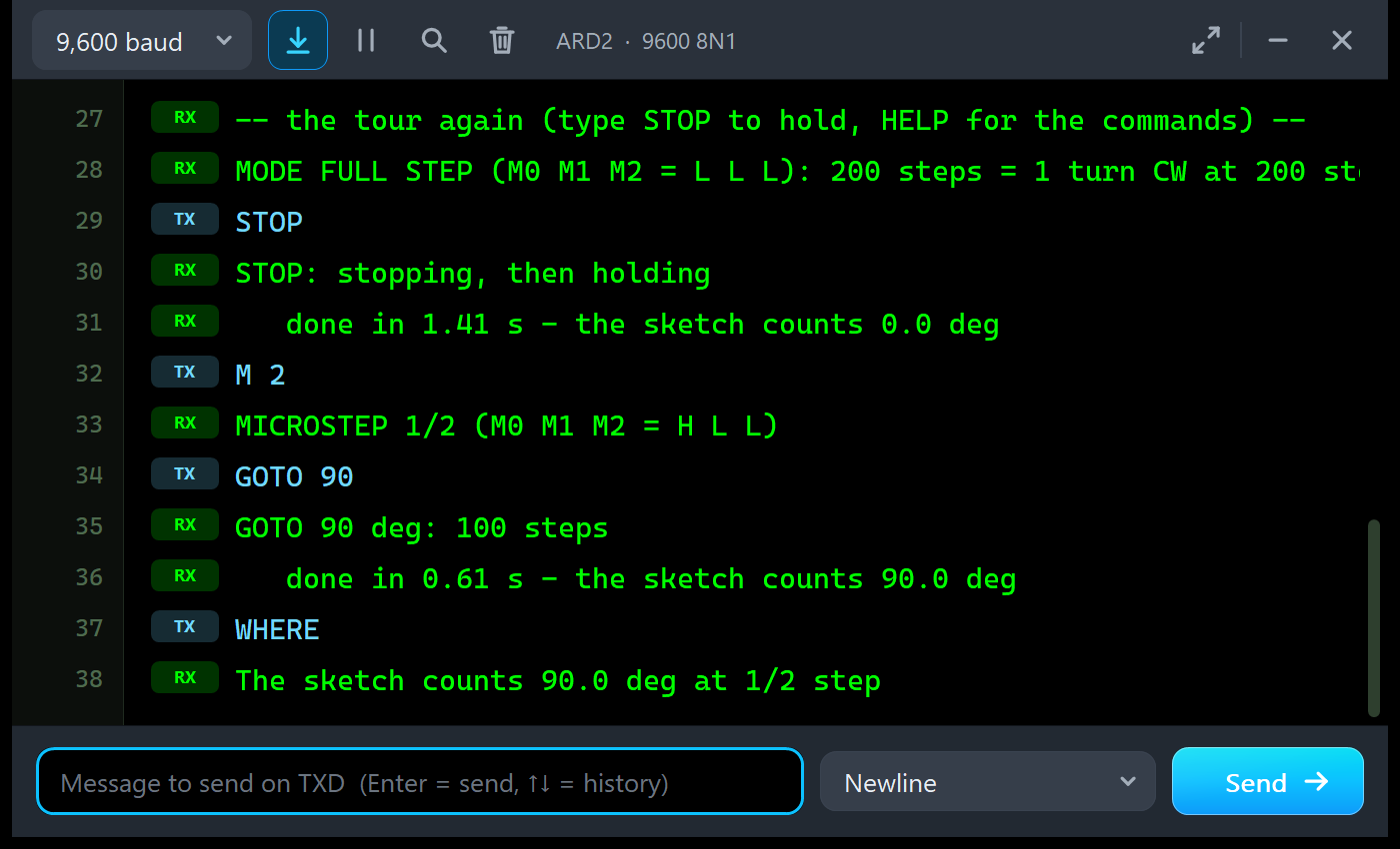
M 2
MICROSTEP 1/2 (M0 M1 M2 = H L L)
GOTO 90
GOTO 90 deg: 100 steps
   done in 0.61 s - the sketch counts 90.0 deg
WHERE
The sketch counts 90.0 deg at 1/2 step
Try EN 1, M 1 and MOVE 200, then EN 0: the STEP LED flashes and the driver counts the 200 steps, but with its outputs off the motor stays where it is, and LOST shows 200 - one whole turn that the sketch believes it made.
The Simulation Log
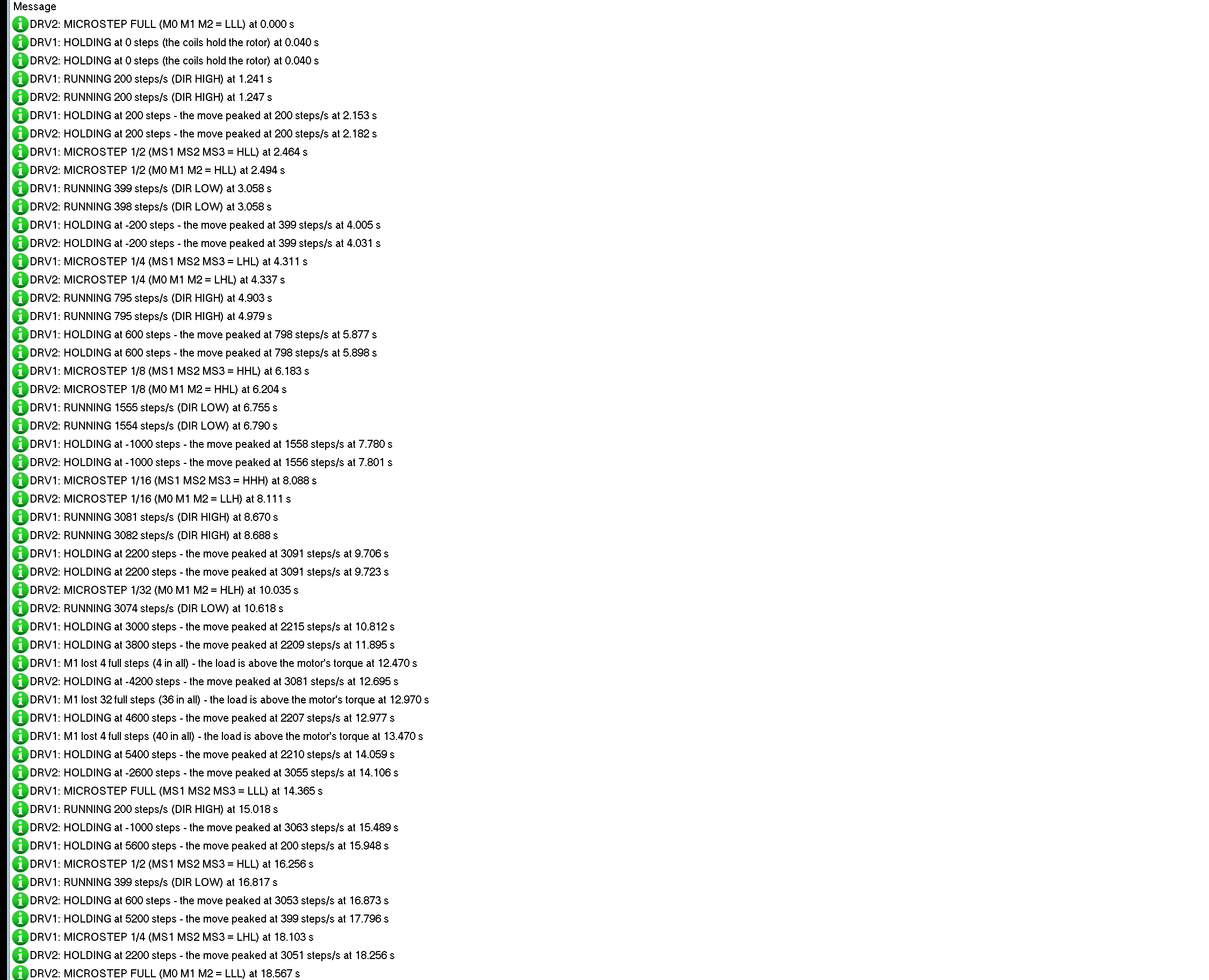
Each driver writes its power-up and every drive change to the simulation log, and each motor writes which driver it follows, for example "follows DRV1 (coil A on its coil 1 / A, coil B on its coil 2 / B)". The lost steps appear with their reason. After 60 drive changes the log stops and points to the Event log, which keeps them all.
How the Driver and the Motor Work Together
Proteus solves the analog part of a circuit in time steps and runs the digital part, here the STEP pulses, between them. A step at 1/32 and 3200 steps/s lasts only 0.3 ms, and the motor must follow every one of them at the right moment. So the driver keeps each STEP edge with its exact time, and the motor, which finds its driver through the wires on its coils, integrates its coils and rotor over every analog step in 10 us pieces from that history.
Inside each piece the chopper works as on the real chip. It drives the full VMOT while a coil current has to grow towards its target, and when the current must fall it can only let it decay: the A4988 uses fast decay for 31 % of the time and the DRV8825 for 75 %. At higher speeds the back-EMF of the turning motor fights the supply, the current cannot follow its target any more, and the torque drops. On a PC we checked this: with a 10 N.cm load the motor lost its steps at 20 turns per second with 12 V, but kept them all with 24 V. That is why printers and CNC machines run their steppers at 24 V or more.
A real stepper also rings after each full step, and at some speeds the ringing can grow until the rotor slips. The model includes the damping of a real motor, so in the demo the full steps ring but never slip without a load.
Troubleshooting
- The motor never moves and the ON LED is dark: no VMOT (NO MOTOR SUPPLY in the banner), or no 5 V on the A4988's VDD.
- The STEP LED flashes but the motor holds still: EN is HIGH (DISABLED), or SLP or RST is LOW or open; on the A4988 tie RST to SLP, on the DRV8825 drive both HIGH.
- The STEP LED never flashes: STEP is not connected or the sketch uses another pin; check the STEP timing tool.
- The motor turns too far or not far enough: check the microstep pins with the Microstep table tool; HHH means 1/16 on the A4988 but 1/32 on the DRV8825.
- The motor turns the wrong way: swap the two wires of one coil, or invert DIR.
- LOST counts up: the load is above the motor's torque, or the speed or acceleration is too high for the current and VMOT.
- No part, no dial or no monitor: TEPSTEPPER.DLL or TEPARDUINO.DLL is missing from MODELS and the project folder; a closed monitor opens again with a click on the UNO's USB port.
Things to Know Before Using a Real A4988 or DRV8825
- The current limit: set it with the trimpot before you connect the motor. Measure VREF between the trimpot and GND: on the A4988 VREF = limit x 0.544, on the DRV8825 VREF = limit / 2. Older A4988 boards with 0.050 ohm resistors use VREF = limit x 0.4.
- A capacitor: put 100 uF across VMOT and GND, close to the board, against the voltage spikes of the chopper.
- Never unplug the motor while VMOT is on: the coil's energy has nowhere to go and the driver dies.
- Heat: above about 1 A (A4988) or 1.5 A (DRV8825) per coil the chip needs a heatsink and some air.
- Acceleration: a loaded motor that starts at full speed misses steps; ramp the speed up and down, as AccelStepper does, and use a higher VMOT for higher speeds.
Limitations of the Simulation
- The coil volts and amps on the schematic's wires are averages of each analog step, not the chopper's PWM; the PWM ripple, the blanking and off times are not modelled.
- The DECAY pin is not modelled (the boards' default mixed decay is used), nor the chips' faults: over-current and thermal shutdown never happen, and FLT stays HIGH while SLP is HIGH.
- Not modelled: heating, the motor's magnetic saturation, the strong resonance of an undamped motor, and damage from a wrong supply or a motor unplugged under power (the model warns about the supply).
- The strip, its LEDs, the panels, the dial and the LOAD button are TEP additions.
- The model is our own, written from the Allegro A4988 and TI DRV8825 datasheets, the carrier boards' documentation and typical data of 1.7 A NEMA 17 motors; this library is not made or endorsed by Allegro MicroSystems, Texas Instruments, Pololu, the makers of the carrier boards or Labcenter.
- Licences: the demo sketch uses AccelStepper (GPL-3.0), so the sketch is GPL-3.0 too; both are in the zip, and the HEX file also contains the Arduino AVR core 1.8.6 with LGPL-licensed code.
- Tested in Proteus 8.5 in October 2026 (the demo as shipped on two Arduino UNO V4.0 boards with their built-in monitors: the tour on both boards, the LOAD button, the commands, the pop-up and the three tools; about 0.43 x real time with the pop-up and both monitors open). Proteus 7 is not supported.
So, that was all about the A4988 / DRV8825 Stepper Driver Library for Proteus V1.0. I hope STEP and DIR, microstepping, the current limit and the danger of lost steps are clear now, so your stepper moves precisely from its first run. If you use the A4988 / DRV8825 Stepper Driver Library for Proteus in a project, please share it in the comments or in our forum, and if you have any questions, ask in the comments and I will help you out. Till the next tutorial, take care and have fun!