Hello friends, I hope you are doing well. This is the sixth tutorial in our series on how to create a Proteus library. In the previous tutorial, How to Use Make Symbol in Proteus, we saw how graphics become reusable symbols and how Proteus layers overlapping shapes. Our Traffic Light Module now has a finished drawing, but it cannot be wired yet, because it has no pins. Today, we change that. Our topic is how to add pins to a component in Proteus.
We will look at the Device Pins mode and its pin types, rotate a pin so that it points the right way, place the four pins GND, R, Y and G exactly at the coordinates of our plan, and then give each pin its name, number and electrical type in the Edit Pin dialogue. We will also decide which pin labels Proteus should draw, see how hidden power pins work, and check the result with the status bar.
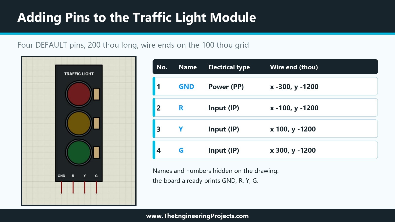
Everything here was done in Proteus 8.5 Professional on our PC, in the same Traffic Light Module project as the previous tutorials. The picture below shows the result: the module with its four pins, and the settings of each pin as Proteus reported them back to us.
What Is a Pin in Proteus?
A pin is the point where a wire connects to a component. In the Proteus help, pins are special device pin objects placed around the body of a part. Each pin carries three pieces of information: a name, a number and an electrical type. The name identifies the pin on the schematic and for the simulation model, the number becomes the pad number on a PCB footprint, and the electrical type tells the electrical rules check and the simulator what the pin does.
A pin has two ends. One end touches the body of the part; the other end, marked with a small blue cross while you draw, is where wires attach. We called it the wire end in our plan. Getting this end on the 100 thou grid is the single most important detail of a library part, because every wire drawn to it later depends on it.
The Device Pins Mode and the Pin Types
Pins are placed with the Device Pins tool in the mode toolbar on the left of the schematic editor. When you select it, the object selector shows the heading PINS and the pin types that Proteus loads by default: DEFAULT, INVERT, POSCLK, NEGCLK, SHORT and BUS. The help adds that further pin types can be picked from the symbol libraries, and that you can even design your own, because pins are symbols too.
| Pin type | Typical use |
|---|---|
| DEFAULT | A plain pin; the right choice for most parts, including our module |
| INVERT | A pin drawn with an inversion mark, for active-low signals |
| POSCLK | A clock input marker for rising-edge clock pins |
| NEGCLK | A clock input marker for falling-edge clock pins |
| SHORT | A shorter pin, for compact symbols |
| BUS | A bus pin that stands for several physical pins |
The DEFAULT pin of Proteus 8.5 is 200 thou long, two grid squares at the default snap. That is exactly the length we planned: from the bottom edge of the board at y = -1000 down to the wire ends at y = -1200.
How to Add Pins in Proteus: Step by Step
Adding the pins takes three steps: point the pin the right way, place it on the grid, and give it a name, number and type.
Step 1: Rotate the Pin to Point Down
A new DEFAULT pin lies horizontally, with its wire end on the left. Our pins must hang down from the bottom edge of the board, like the header of the real module. Below the 2D graphics tools, the mode toolbar has two rotation buttons and a small box that shows the current angle, followed by two mirror buttons. With the Device Pins tool active, we clicked the rotation button once; the angle box changed from 0 to 90 degrees, and the preview at the top of the object selector showed a vertical pin.
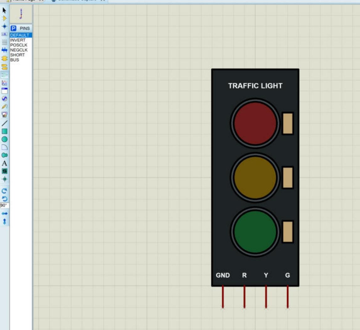
To be sure which end is which, move the mouse over the sheet before placing anything. After the first click, an outline of the pin follows the mouse. In our case, the mouse held the top end of the vertical pin, and the small cross of the wire end was at the bottom, which is exactly what we wanted.
Step 2: Place the Four Pins on the Grid
With Snap 0.1in active (F3), we used the coordinate display to put each pin precisely.
- Move the mouse until the display reads -300, -1000. The outline now runs from the board edge down to y = -1200, with the cross at the bottom. Click to place the GND pin.
- Move to -100, -1000 and click for the R pin.
- Move to 100, -1000 and click for the Y pin.
- Move to 300, -1000 and click for the G pin.
- Right-click an empty part of the sheet to stop placing pins, then choose the selection mode.
One practical warning: while the Device Pins tool is active, every left click places another pin. If you click somewhere by mistake, you get an extra pin there; delete it with a right-click on it and Delete Object, or undo the last step. Ending the mode with a right-click on empty space, as in step 5, avoids surprises.
The new pins are drawn in the PIN graphics style, a dark red line, like the pins of every other part. That is deliberate: pins should look the same in every component, so we leave them in the global PIN style instead of giving them local colours.
Step 3: Name, Number and Type Each Pin in the Edit Pin Dialogue
A freshly placed pin has no name and no number. In selection mode, right-click the GND pin and choose Edit Properties. The Edit Pin dialogue opens.
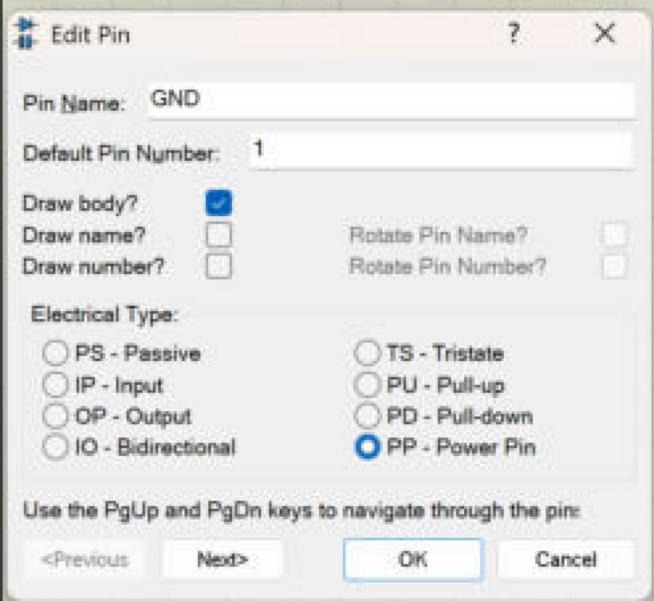
The dialogue has these fields:
The Fields of the Edit Pin Dialogue
- Pin Name: the name of the pin. In our dialogue, the OK button stayed greyed out until we had entered a name; the help states that a pin must always have a name.
- Default Pin Number: the pin number. For a simple single-element part like ours, it can be entered here; for multi-element parts and bus pins, pin numbers are assigned in the Visual Packaging Tool instead.
- Draw body?: unticked, it hides the whole pin and turns it into a hidden pin.
- Draw name? and Draw number?: whether Proteus prints the name and the number next to the pin, with options to rotate them.
- Electrical Type: PS Passive, IP Input, OP Output, IO Bidirectional, TS Tristate, PU Pull-up, PD Pull-down or PP Power Pin.
- Previous and Next: move to the previous or next pin without closing the dialogue; PgUp and PgDn do the same.
For the GND pin, we entered the name GND, the number 1, unticked Draw name and Draw number, and chose PP Power Pin. Then we clicked Next, and the dialogue moved to the R pin, which Proteus highlighted on the sheet. R became number 2 with type IP Input, Y number 3 and G number 4, both inputs as well, each with the name and number hidden. On the last pin, the Next button greyed out, and OK stored all four.
The Choices Behind Our Pins
Two choices in the Edit Pin dialogue deserve an explanation: the electrical types and the hidden labels.
Why We Chose These Electrical Types
- R, Y and G are inputs (IP). On the real module, these pins only receive a level from the Arduino and never drive anything back. The help lists Input as the type for analogue or digital device inputs.
- GND is a power pin (PP). It is the common cathode of the three LEDs and goes to the ground of the circuit. The help lists Power for power and ground supply pins.
- Not passive. Passive (PS) suits the terminals of resistors and capacitors. It would also work for the electrical rules check, but the help points out that the electrical type must be right for digital simulation models in particular, and our module will get such a model later.
Why We Hid the Pin Names and Numbers
Proteus can print each pin's name and number next to it, and for a box symbol that is exactly what you want: the names tell the reader what each pin does. Our module is different. Its board already carries the labels GND, R, Y and G in white, right above the pins, just like the silkscreen of the real board. Proteus labels would repeat them in another font and colour and clutter the bottom of the module. The pin numbers would add nothing for a part that is used mainly in simulations.
Hiding them changes only the drawing. The names and numbers are still stored in the pins: the netlist, the electrical rules check and the simulation model all see them. You can check this at any time by moving the mouse over a pin: the status bar at the bottom of the window shows its name, number and type. For our pins it read Name=GND, Number=1 and a power type for the first pin, and Name=R, Number=2, Name=Y, Number=3 and Name=G, Number=4 with the type INPUT for the others.
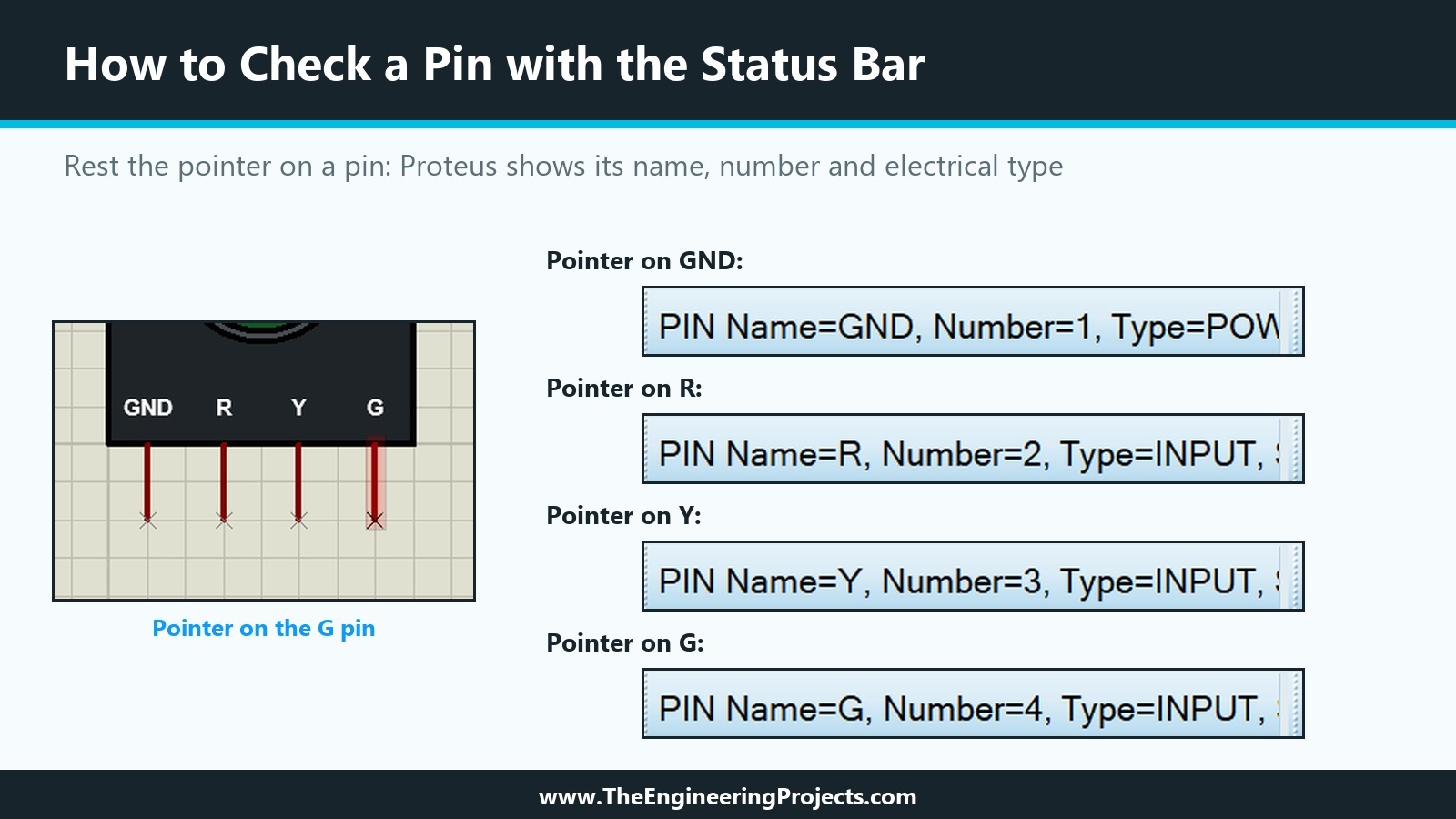
The status panel of Proteus 8.5 is narrow and cuts the text off after the type, so for the GND pin only the start of the word POWER fits. If you need the full details of a pin, open its Edit Pin dialogue instead.
Pin Rules Every Library Maker Should Know
A few rules about pins come up in every library, whatever the part.
Hidden Pins and Power Pins
Untick Draw body?, and the pin disappears from the drawing; only a small cross marks it while you edit the part. The help explains what happens to such a hidden pin: at netlist time, it is connected automatically to a net with the same name as the pin, so a hidden VCC pin joins the VCC net and a hidden GND pin joins the GND net, unless a user property of the component, such as VCC=+5V, names another net.
Hidden power pins are almost essential for digital chips with many supply pins, where wiring every VCC and GND would clutter the schematic. For our four-pin module, we kept GND visible: the real module has a GND pin that has to be wired, and a visible pin teaches students to wire it. The help also offers a second kind of hidden pin, added only in the packaging, which we will meet in the packaging tutorial.
Pin Names: Rules Worth Knowing
- Every pin needs a name. If you type only a number, Proteus uses the number as the name.
- Equal names are connected. Two pins with the same name are treated as connected in the netlist and on the PCB. That is useful for several GND pins of one chip, but dangerous by accident.
- Overbars use dollar signs. A name such as RD/$WR$ is drawn with a bar over WR, the usual way to mark an active-low signal.
- Keep names short and identical to the real part. Students compare the board and the screen, and a simulation model will look up the pins by these names.
Another Way: The Property Assignment Tool
For parts with many pins, editing each pin in turn is slow. The help describes a second method: the Property Assignment Tool, which assigns the properties PINNAME, PINNUM and TYPE to tagged pins in one go. In practice, the help recommends a mix: names and types with whichever method is faster, and pin numbers in the Visual Packaging Tool for anything more complex than a single-element part. For our four pins, the Edit Pin dialogue with its Next button was the quickest way.
How These Pins Are Used Later in the Series
The four pins we placed today will be read by three later steps, which is why their details matter so much.
- Make Device stores the pins together with the graphics as one device. From then on, the pin positions decide where wires attach on every copy of the part.
- Packaging maps the pin numbers to the pads of a PCB footprint. Because we numbered the pins 1 to 4 in the order of the real header, a standard four-pin header footprint will fit without renumbering.
- The simulation model finds its pins by name. In the model code of our own module libraries, the DLL asks Proteus for each pin by its name, for example "VCC", "GND", "RXD" and "TXD" in our HC-12 model. Our traffic light model will ask for "R", "Y", "G" and "GND" in the same way, so a renamed pin would break the model.
Our Pin Checklist
| Check | How we checked it | Result |
|---|---|---|
| Wire ends on the 100 thou grid | Coordinate display while placing | x = -300, -100, 100, 300 at y = -1200 |
| Wire end away from the body | The cross of the pin outline | At the bottom end of each pin |
| Names match the real board | Status bar on hover | GND, R, Y, G |
| Numbers follow the header order | Status bar on hover | 1, 2, 3, 4 |
| Electrical types | Status bar on hover | Power for GND, Input for R, Y, G |
| No duplicate names | Edit Pin with Next | Four different names |
| Project saved | File timestamp | Saved after the pin edits |
Common Mistakes When Adding Pins in Proteus
| Problem | Cause | Solution |
|---|---|---|
| Wires connect to the wrong end of a pin | The pin was placed the wrong way round | Check the position of the cross; rotate or mirror before placing |
| Wires bend when connected | The wire end is off the 100 thou grid | Place pins with Snap 0.1in and watch the coordinate display |
| Extra pins appear on the sheet | Clicks made while the Device Pins tool was still active | End the mode with a right-click on empty space; delete stray pins |
| OK is greyed out in Edit Pin | The pin has no name yet | Type a pin name |
| Two pins behave as one | They have the same name | Give every pin a unique name unless they really are connected |
| The simulation model cannot find a pin | The name differs from the one the model uses | Use exactly the names of the plan |
In the Next Tutorial
Our Traffic Light Module now has its graphics and its pins, which is everything a device element needs. In the next tutorial, How to Use Make Device in Proteus to Create a New Part, we will tag the whole drawing, run the Make Device wizard page by page, give the part its name and reference prefix, add its first properties and index data, and store it in a library, so that it can be picked like any other Proteus component.
FAQ
How do I add a pin to a component in Proteus?
Select the Device Pins tool in the mode toolbar, choose a pin type such as DEFAULT, rotate it if needed, and click on the sheet to place it with its wire end away from the body. Then right-click the pin, choose Edit Properties and enter its name, number and electrical type.
How long is a default pin in Proteus?
In Proteus 8.5, the DEFAULT pin is 200 thou long, two grid squares at Snap 0.1in.
Which end of a Proteus pin connects to the wire?
The end marked with the small blue cross. It must point away from the body of the part and should lie on the 100 thou grid.
What electrical type should I give a pin in Proteus?
Input for pins that only receive a signal, Output for driven outputs, Bidirectional for data buses, Power for supply and ground pins, and Passive for the terminals of passive parts. Tristate, Pull-up and Pull-down cover the remaining kinds of output.
How do I hide the pin name in Proteus?
Untick Draw name? in the Edit Pin dialogue. The name is still stored and used; it is just not printed on the drawing.
What is a hidden pin in Proteus?
A pin whose body is not drawn. At netlist time, it is connected to the net with the same name as the pin, which is how hidden VCC and GND pins of chips get connected.
That is all for today. Our module now has four correctly placed and named pins. If you have any questions, ask in the comments. Take care.