Hello friends, I hope you are doing well. This is the fifth tutorial in our series on how to create a Proteus library. In the previous tutorial, How to Make a Realistic Component in Proteus, we gave our Traffic Light Module its final colours and saw why a realistic part should carry local colours instead of following the global style. Today, we look at how Proteus groups graphics into reusable building blocks. Our topic is how to use Make Symbol in Proteus, together with the way Proteus layers overlapping shapes.
We will see what a symbol is, where Proteus stores symbols, how to tag a group of shapes with a tag box, how to turn them into a symbol with the Make Symbol command, how to find and place the symbol again with the Pick Symbols browser, and how to break it apart with Decompose. As our example, we turned the red lamp of our module, the lamp and its grey ring, into a symbol called TRAFFIC_LAMP_RED.
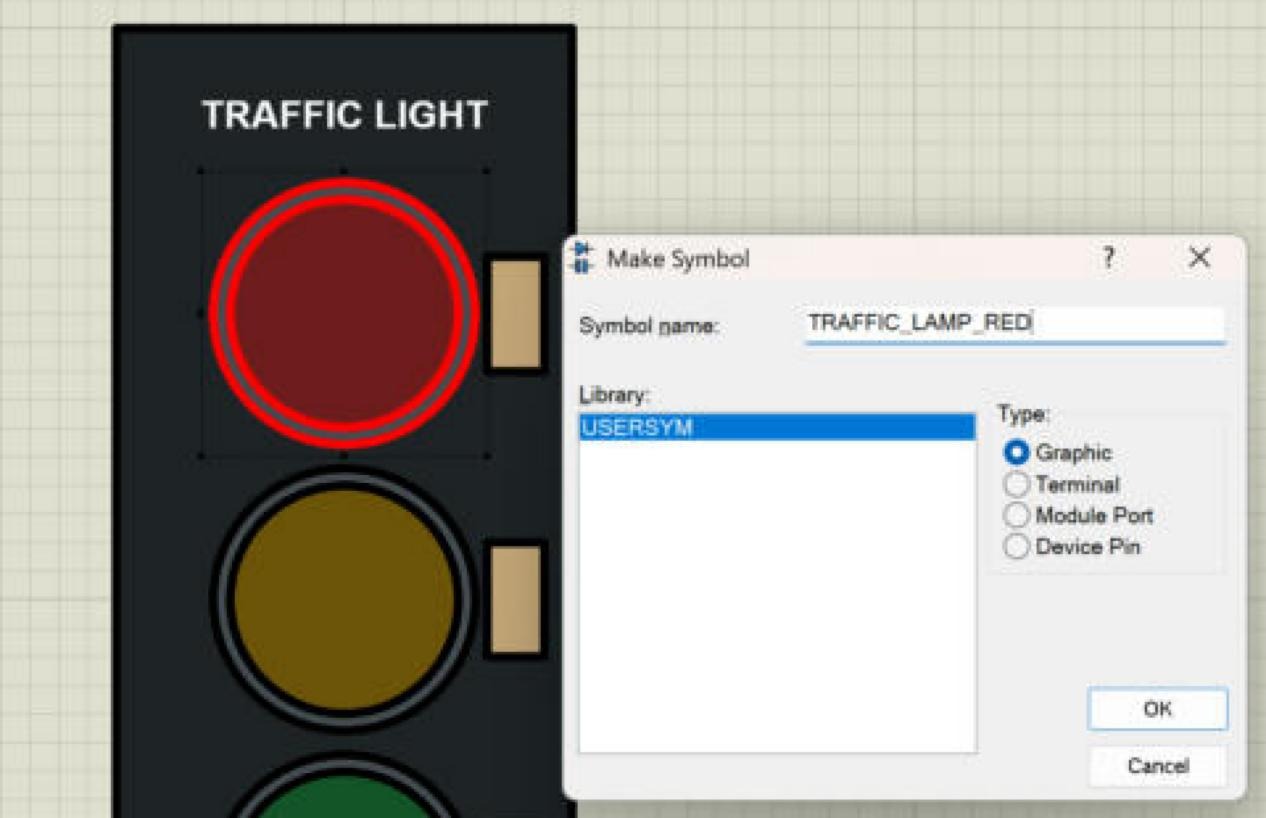
Everything shown here was done in Proteus 8.5 Professional on our own PC, in the same project as the previous tutorials. The picture below shows the moment of creation: the lamp and its ring are tagged (outlined in red), and the Make Symbol dialogue is filled in.
What Is a Symbol in Proteus?
The Proteus help defines a symbol as a group of 2D graphics objects that are treated as a single object. Using three lines and two arcs, for example, you can form an AND gate symbol and then place it again and again. A symbol is only graphics: it has no pins, no properties and no simulation model. The help stresses that symbols are not component devices; a device is made later with the Make Device command and may use symbols in its drawing.
Proteus uses symbols for much more than decoration. Terminals, module ports and device pins are all symbols as well, stored with name prefixes that keep them apart. When you place an INPUT terminal, you are really placing the symbol $TERINPUT from SYSTEM.LIB. That is why the Make Symbol dialogue asks for a type: Graphic, Terminal, Module Port or Device Pin. In this tutorial, we make an ordinary graphic symbol; terminals and pins follow the same procedure with a few extra markers, which we meet when we add pins in the next tutorial.
Where Does Proteus Store Symbols?
Symbols live in symbol libraries. Proteus 8.5 comes with SYSTEM.LIB, which holds the standard symbols, terminals, ports and pin shapes, and USERSYM.LIB, an empty read/write library for your own symbols. In the Pick Symbols browser, these two appear as SYSTEM and USERSYM. The help warns that items must never be removed from SYSTEM.LIB, so your own symbols always go into USERSYM or a symbol library of your own.
On our PC, USERSYM.LIB grew from 6560 to 6808 bytes when we saved our lamp symbol into it. That is a useful reminder that a symbol is stored in the library on disk, not only in the open design.
Why Use Symbols When Designing a Component?
- Reuse. A lamp, a chip outline, a connector or a logo that you have drawn carefully once can be placed in other parts. Our lamp could become the lamp of a future single LED module.
- One object instead of many. A placed symbol moves, rotates and copies as one object, so a detailed group cannot fall apart while you arrange a drawing.
- Consistency. Every copy placed from the library looks exactly the same.
- Building blocks. The help explains that a symbol may contain other symbols and other graphics, so you can build a complex drawing from tested pieces.
- Animation. Animated parts in Proteus show their states with symbols. In the second part of this series, the off and on looks of our lamps become such symbols.
How Proteus Layers Overlapping Shapes
Before we group anything, it helps to understand how Proteus decides which shape is in front. In our drawing, the rule was simple and consistent: a shape placed later is drawn on top of shapes placed earlier. The board was drawn first, so everything else appears on it. The rings were drawn next, and the lamps after them, so each lamp sits inside its ring. The copies made with Block Copy are new objects too, so the copied lamps also appeared on top of their rings.
The schematic editor does not show layers the way a paint program does; the order of placement is the layering. This is why we planned our drawing in groups in the second tutorial and drew them from the bottom up: board, rings, lamps, resistors, text. If a filled shape ends up in front of something it should hide behind, the simplest fix is to redraw the hidden detail, or to copy it with Block Copy and delete the original, because the copy is newer and therefore on top.
A symbol keeps the order of its parts inside it. Our lamp symbol was made from a ring placed first and a lamp placed later, so the lamp stays in front of the ring wherever the symbol is used.
How to Use Make Symbol in Proteus: Step by Step
Making a symbol takes four steps: tag the shapes, run Make Symbol, find the symbol in the browser, and place it. We made our lamp symbol exactly this way.
Step 1: Tag the Shapes with a Tag Box
Make Symbol works on the tagged (selected) objects, so the first job is to tag exactly the shapes that belong to the symbol, and nothing else.
- Choose the selection mode, the arrow at the top of the mode toolbar.
- Press the left mouse button on an empty spot outside the ring, drag diagonally across the ring, and release on the other side. A dashed tag box follows the mouse.
- Every object that lies completely inside the tag box is tagged and drawn with a red outline.
The word "completely" is the key. Our tag box ran from just outside the ring on the left to just outside the ring on the right, about 490 thou wide around a ring of 460 thou. The ring and the lamp lay fully inside it and were tagged. The resistor next to the lamp starts at x = 250 thou, just beyond the right edge of the box at about 240, so it stayed untagged, and the board, which is much larger, stayed untagged too. Starting the drag on top of the board worked fine, because a filled shape is only picked by its outline.
Step 2: Run Library, Make Symbol
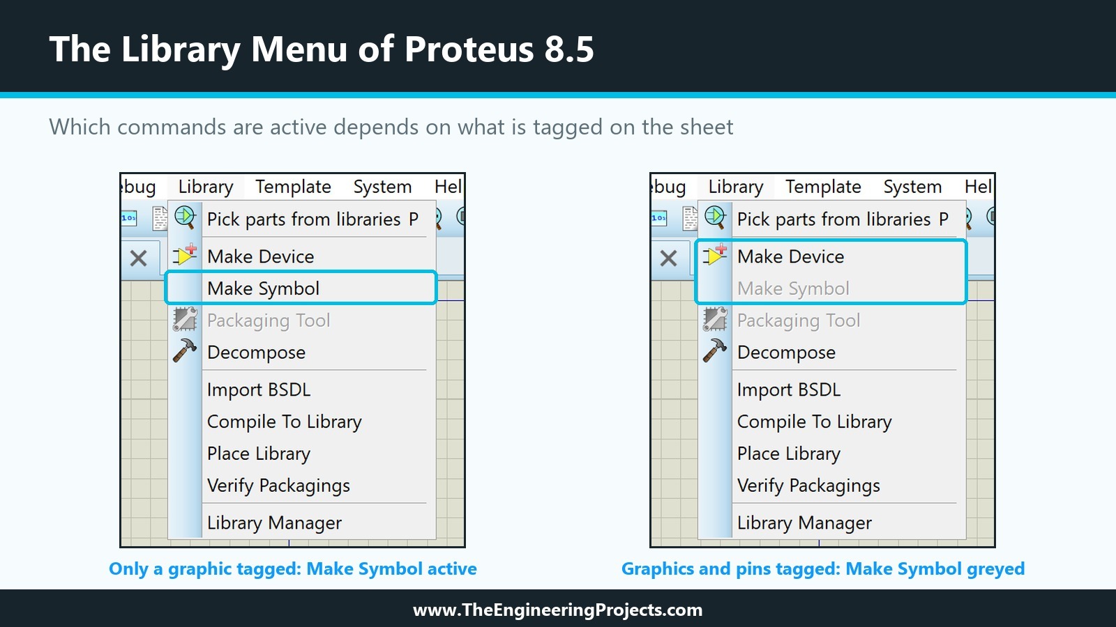
With the lamp and ring tagged, open the Library menu. In Proteus 8.5, it lists Pick parts from libraries, Make Device, Make Symbol, Packaging Tool, Decompose, Import BSDL, Compile To Library, Place Library, Verify Packagings and Library Manager; some of them are only active when something suitable is tagged. The picture below shows the menu twice. With only a graphic tagged (for this test, one resistor of the module), Make Symbol is active. With the whole drawing tagged, pins included, Make Symbol is greyed out and Make Device is the command to use, which matches the rule from the help that a symbol holds only 2D graphics and markers.
With the lamp and ring tagged, choose Make Symbol. The dialogue has three fields:
The Three Fields of Make Symbol
- Symbol name: the name under which the symbol is stored. We typed TRAFFIC_LAMP_RED. Use a clear, unique name without spaces; once you have dozens of symbols, a common prefix keeps related symbols together in the list.
- Library: the symbol library to store it in. Only USERSYM was offered on our installation, and it was already selected.
- Type: Graphic, Terminal, Module Port or Device Pin. For a lamp, Graphic is right.
Click OK, and the symbol is stored. One behaviour surprised us at first: the ring and the lamp on the sheet stayed exactly as they were, two separate shapes. Make Symbol saves a copy of the tagged graphics as a symbol in the library; it does not replace them in the drawing. When we right-clicked the ring afterwards, only the ring was selected, and Decompose was greyed out, which shows it was still a plain circle.
Step 3: Find the Symbol in the Pick Symbols Browser
To place a symbol, select the 2D Symbol tool in the mode toolbar. The object selector then lists the symbols already loaded into the design; our new symbol appeared there at once. To see all symbols, click the P button at the top of the selector. The Pick Symbols browser opens with three areas: the Libraries list, the Objects in the selected library, and a large preview.
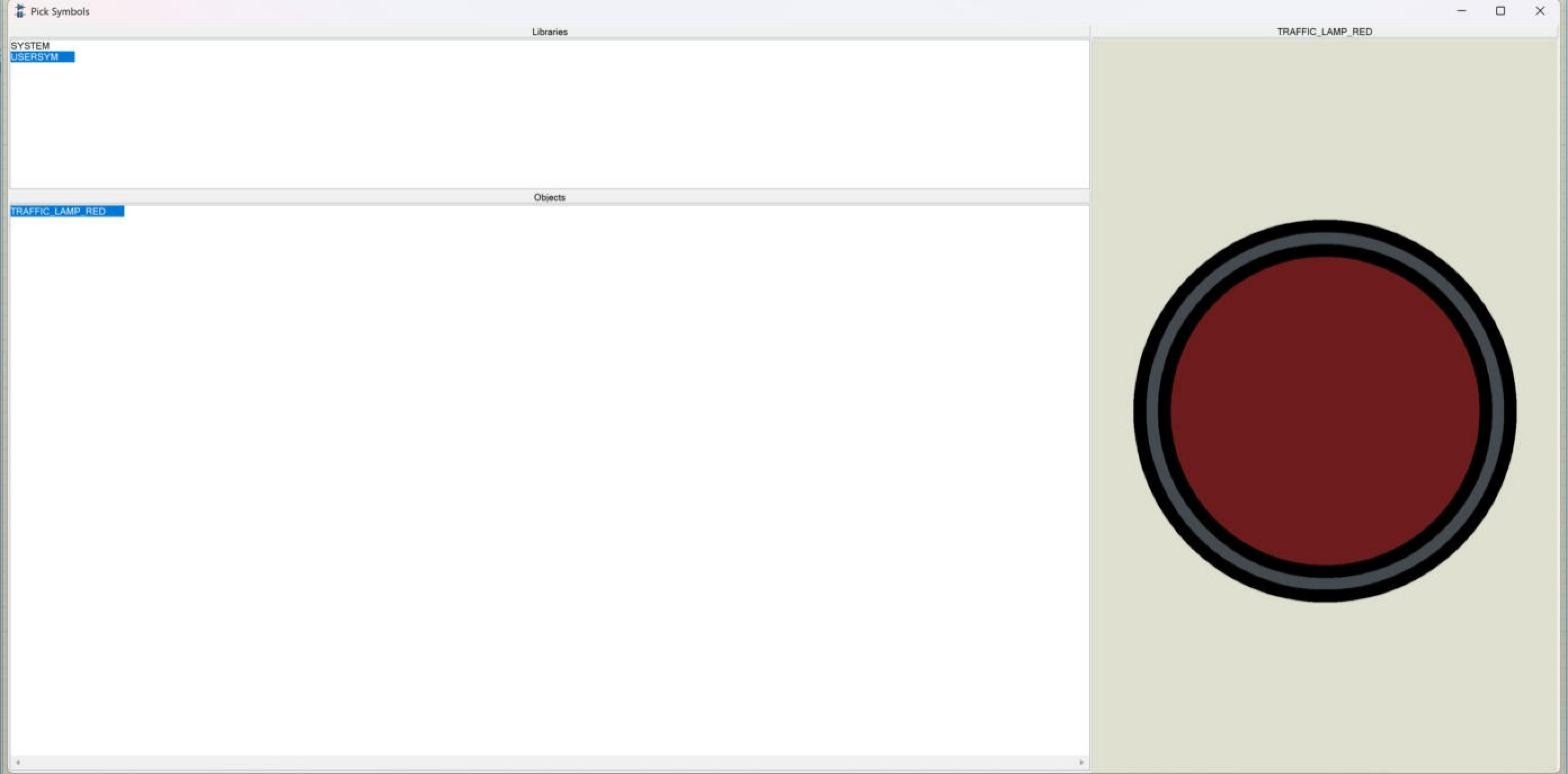
With SYSTEM selected, the Objects list is long: generator, marker and drill symbols with a dollar prefix, terminal and pin shapes, and drawing symbols such as HEADER, INVERTER, OPAMP, ORIGIN and several potentiometer and transistor shapes. With USERSYM selected, it showed a single entry, TRAFFIC_LAMP_RED, and the preview showed our lamp with its ring exactly as drawn, colours included.
Step 4: Place the Symbol and Decompose It
Back on the sheet, with the 2D Symbol tool and TRAFFIC_LAMP_RED selected, a click on the sheet starts the placement: an outline of the symbol follows the mouse. A second click fixes it. The help describes the same two-click placement and notes that you can rotate or mirror the symbol before placing it.
We placed one copy next to the module. Since we did not put an Origin marker into the symbol, Proteus used the default the help describes for symbols, the centre of the symbol, and the lamp centred itself on the click point. Right-clicking the placed symbol selected both circles together, and the context menu now offered Decompose.
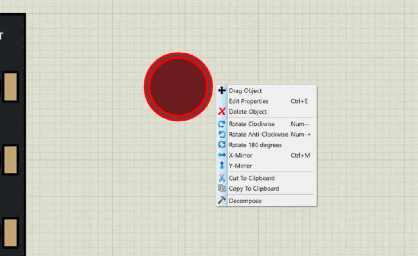
Decompose breaks a placed symbol back into its graphics and markers. The help recommends exactly this route for editing a symbol: place an instance, decompose it, change the graphics, and make the symbol again with the same name. A symbol made from other symbols is not linked to them, so changing or deleting the lower-level symbol later does not change the new one. After our test, we deleted the placed copy and saved the project; the module itself still consists of separate shapes, which is what the next tutorials expect.
Adding an Origin Marker to a Symbol
For a round lamp, the centre is a natural reference point. For other symbols, you may want a different one, for example the bottom left corner of a connector, so that it snaps neatly to the grid. The help describes how: select the Markers tool, pick the Origin marker from the selector, place it where the origin should be, and tag it together with the graphics before running Make Symbol. Without an Origin marker, a symbol uses its centre; a device, as we saw in the first tutorial, uses the end of its top left pin.
Symbols for Terminals, Module Ports and Device Pins
The other three types in the Make Symbol dialogue follow the same steps with extra markers that tell Proteus where wires connect and where labels go. From the help:
| Type | Usual graphics style | Markers to place |
|---|---|---|
| Graphic | Any, often COMPONENT | Origin (optional) |
| Terminal | TERMINAL | Node or Busnode for the wire, Label for the net name, Origin (optional) |
| Module Port | PORT | Node or Busnode, Label, and an Origin at the edge of the sub-circuit |
| Device Pin | PIN, or BUS WIRE for a bus pin | Node or Busnode, Pinname and Pinnum markers, Origin (optional) |
The help also notes two limits that apply to every type: a symbol can only consist of 2D graphics and markers, so you cannot tag a piece of circuit with components and wires and make it a symbol, and the electrical type of a user-defined terminal defaults to passive.
How We Will Use Symbols in Our Traffic Light Module
TRAFFIC_LAMP_RED is our first symbol and, for now, a practice piece: it shows how a lamp with its ring becomes one reusable object. Its real job comes later in the series. An animated part shows its states with a set of symbols, and our planned bitwise states need an off and an on symbol for each of the three lamps. Those symbols will be made exactly as in this tutorial, from the shapes of each lamp in their off and on colours, and named after the convention the Make Device wizard expects.
Until then, the module stays as separate shapes, because the next step, adding pins, and the one after it, Make Device, work on the tagged graphics of the whole drawing.
How to Name Your Symbols
Symbol names look unimportant when a library holds one symbol. They matter as soon as it holds fifty, because the Pick Symbols browser simply lists them by name. A simple scheme keeps a library tidy:
- Start with the part or project. TRAFFIC_ for everything that belongs to the Traffic Light Module, so all its symbols stand together in the list.
- Then say what it is. LAMP, RING, LOGO, CONNECTOR.
- Then the variant. RED, YELLOW, GREEN, or a size.
- Use capitals and underscores, no spaces. That matches the style of the supplied libraries and avoids surprises in scripts and property values.
Our TRAFFIC_LAMP_RED follows this pattern. For animation symbols, the name is not free: the Make Device wizard builds the names from a symbol name stem, an element number and a state, so we will choose the stem with the same care when we get there.
Common Mistakes with Make Symbol in Proteus
| Problem | Cause | Solution |
|---|---|---|
| A shape is missing from the symbol | It reached outside the tag box and was not tagged | Draw a larger tag box, or check the red outlines before Make Symbol |
| An unwanted shape is in the symbol | It lay completely inside the tag box | Make the box smaller, or move the shape away first |
| The drawing did not change after Make Symbol | Make Symbol stores a copy in the library | Place the symbol with the 2D Symbol tool where you need it |
| Make Symbol is greyed out | Nothing is tagged | Tag the graphics first |
| Components and wires cannot be made into a symbol | Symbols hold only 2D graphics and markers | Use Export Section and Import Section for pieces of circuit |
| The symbol is placed off the grid | Its origin is its centre | Add an Origin marker at a grid point before Make Symbol |
In the Next Tutorial
Our drawing is complete, and we know how to group graphics into symbols. In the next tutorial, How to Add Pins to a Component in Proteus, we will place the four pins of our Traffic Light Module, GND, R, Y and G, give them names, numbers and electrical types, and put their wire ends exactly on the 100 thou grid.
FAQ
How do I make a symbol in Proteus?
Draw the graphics, tag them with a tag box in selection mode, choose Library, Make Symbol, type a name, select a library such as USERSYM, choose the type Graphic and click OK.
What is the difference between a symbol and a device in Proteus?
A symbol is a group of 2D graphics treated as one object, with no pins or properties. A device is a complete part with graphics, pins, properties, packaging and possibly a simulation model, made with Make Device.
Where are user symbols stored in Proteus?
In a symbol library, normally USERSYM.LIB in the Proteus library folder, or in a symbol library of your own. Never store or remove symbols in SYSTEM.LIB.
How do I edit a symbol in Proteus?
Place an instance with the 2D Symbol tool, right-click it, choose Decompose, edit the graphics, tag them again and run Make Symbol with the same name.
Does Make Symbol replace my graphics with the symbol?
No, not in our test in Proteus 8.5: the tagged graphics stayed on the sheet as separate shapes, and the symbol was stored in the library. Place the symbol with the 2D Symbol tool where you need it.
How does Proteus decide which shape is on top?
In our drawings, the shape placed later was always drawn on top. Draw the background first and the details last.
That is all for today. Our lamp is now a reusable symbol, and our module is ready for its pins. If you have any questions, ask in the comments. Take care.