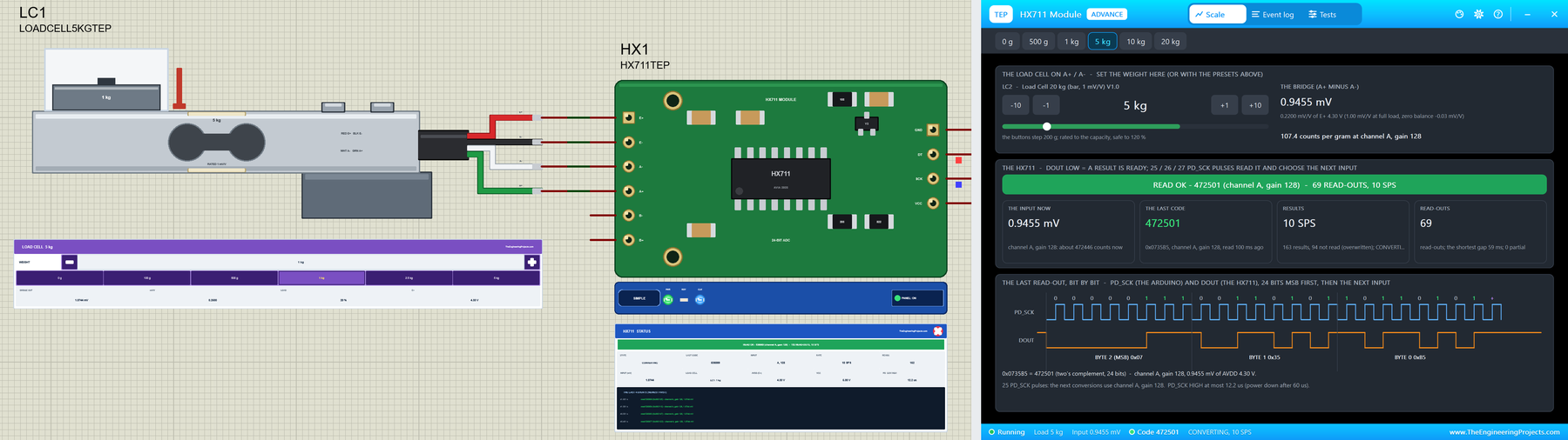
Hello friends, I hope you all are doing great. Today, I am going to share the new HX711 Load Cell Library for Proteus V1.0. The HX711 and a bar load cell are the heart of nearly every Arduino scale: kitchen scales, parcel scales, beehive scales, filament spool scales and force testers. The load cell turns the weight into a few millivolts, and the HX711 turns those millivolts into a 24-bit number. Now you can build the whole weighing chain in Proteus, with the green HX711 module and the aluminium load cells of 1, 5 and 20 kg.
Behind the parts sit our own models, not a part that shows a number. The load cell is a real Wheatstone bridge in the analog simulation, unbalanced by the weight you put on it. The HX711 drives the bridge from its 4.3 V regulator, converts the bridge voltage like the real chip, ratiometric, 24 bits, two's complement, and sends it to the Arduino bit by bit on DOUT and PD_SCK, with the gain chosen by the number of pulses, the settling time and the power down. You get five devices: the HX711 as a Simple device with a live STATUS panel and as an Advance device with a pop-up window and three test tools, and the three load cells, each with a WEIGHT panel. The demo runs the HX711 library on our Arduino UNO V4.0.
NOTICE: a scale is easy to fake: read a weight from a property and hand it to the Arduino. We wanted more. Our load cell is a real bridge with a few millivolts on its outputs, and our HX711 answers the PD_SCK pulses bit by bit, so the HX711 library tares it, calibrates it and reads it exactly as on your desk, and the classic mistakes fail exactly as they do there. It took our team a lot of hard work. Your feedback is the fuel that keeps us going, so please tell us what you think in the comments below or in the HX711 board of our forum. And if our free libraries help you, you can buy us a coffee. So, let's get started with the HX711 Load Cell Library for Proteus V1.0:
What is the HX711?
The HX711 is a 24-bit analog-to-digital converter from Avia Semiconductor, made for weigh scales. It has a low-noise amplifier in front of the converter and two differential inputs: channel A with a gain of 128 or 64 for the load cell, and channel B with a gain of 32. It needs no SPI or I2C: it sends its result on DOUT when the microcontroller clocks PD_SCK. The cheap green module carries the chip, the transistor and resistors of its AVDD regulator, which also feeds the load cell on E+, and two headers: E+, E-, A-, A+, B-, B+ for the load cell and GND, DT, SCK, VCC for the Arduino.
| HX711 | |
|---|---|
| Resolution | 24 bits, two's complement: 0x800000 to 0x7FFFFF |
| Inputs | channel A, gain 128 or 64; channel B, gain 32 (differential) |
| Input range | +-0.5 x AVDD / gain: +-16.8 mV at gain 128 with AVDD 4.3 V |
| Data rate | 10 samples a second (RATE to GND) or 80 |
| Settling | 4 conversions after a reset, a wake-up or an input change: 400 ms at 10 SPS |
| Supply | 2.6 to 5.5 V on VCC; the module's regulator gives AVDD = E+ = 4.3 V |
| Interface | DOUT (DT) and PD_SCK (SCK): 25, 26 or 27 pulses a read-out |
| Devices | HX711TEP (Simple), HX711ADVTEP (Advance), LOADCELL1KGTEP, LOADCELL5KGTEP, LOADCELL20KGTEP |
How a Load Cell Works
A bar load cell is a block of aluminium with a hole that makes it bend in a known way. Four strain gauges are glued on it and wired as a Wheatstone bridge: two of them stretch and two of them shrink under the weight. The bridge is fed on E+ and E- (the red and black wires) and its middle points are the outputs A+ and A- (green and white). Without a weight the outputs are almost equal; with a weight they drift apart by a few millivolts. The data sheet calls this the rated output, usually 1 mV/V: at full load the output is 1 mV for every volt on E+, so 4.3 mV with the HX711 module. A small output at no load, the zero balance, is normal, and that is why every scale needs a tare. For the mechanics of a load cell, read our Design of a Load Cell.
How the HX711 Sends a Reading
When a conversion is done, the HX711 pulls DOUT LOW: a result is ready. The Arduino then sends pulses on PD_SCK, and after each rising edge the HX711 puts the next bit on DOUT, MSB first. 24 pulses read the 24 bits; then 1, 2 or 3 more pulses choose the input for the next conversions: 25 pulses in all for channel A with gain 128, 26 for channel B with gain 32, and 27 for channel A with gain 64. A change of the input restarts the converter, so the next result comes 4 conversions later. If PD_SCK stays HIGH for more than 60 us, the HX711 powers down; when it goes LOW again, the chip wakes up with channel A and gain 128.
Counts per Gram
The HX711 is ratiometric: the bridge and the converter use the same AVDD, so the result depends only on the weight. A full load gives 1 mV/V, and the gain of 128 makes that 0.128 of the converter's span of 16,777,216 counts: about 2,147,000 counts. Divide it by the capacity and you get the counts per gram: about 2147 for a 1 kg cell, 429.5 for a 5 kg cell and 107.4 for a 20 kg cell. That is the calibration factor the HX711 library wants in set_scale(). Real cells differ from their rated output by up to 15 percent (1.0 +-0.15 mV/V is a typical specification), which is why you calibrate every cell with a known weight.
What's New in HX711 Load Cell Library for Proteus V1.0
- Real parts: the green HX711 module drawn at twice its real size, and the aluminium bar load cell at its real length with its four coloured wires and a weight on its loaded end.
- Two styles: the HX711 as a Simple device with a STATUS panel and as an Advance device with a pop-up window.
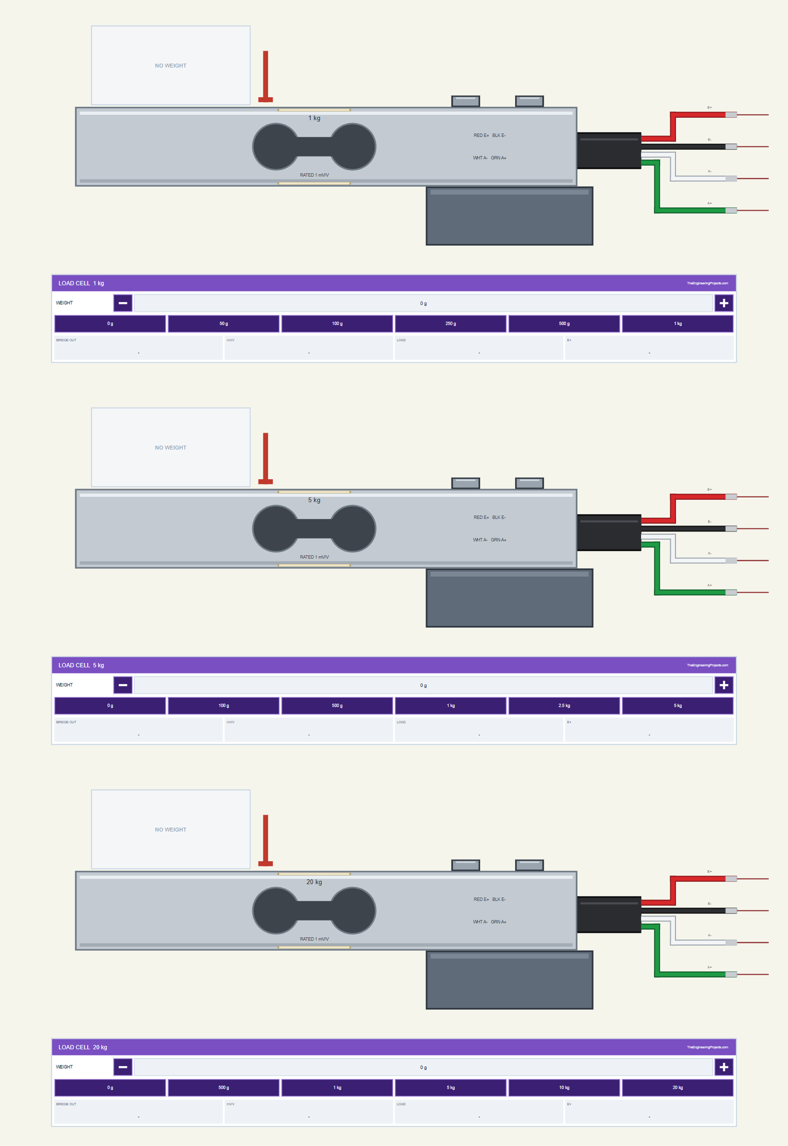
- Three load cells: 1, 5 and 20 kg, each a 1 kohm full bridge with its rated output and zero balance, and a WEIGHT panel with - / + buttons and six presets.
- The real converter: 24 bits, ratiometric, channel A at gain 128 or 64 and channel B at gain 32, saturation, noise, 10 or 80 samples a second and the settling of 4 conversions.
- The real read-out: DOUT LOW when ready, 25 to 27 PD_SCK pulses, the next input, power down after 60 us and the wake-up at gain 128.
- Mistake detection: pulses without a result, too few pulses, PD_SCK HIGH too long, saturation and an overloaded cell, each with a clear note.
- Three test tools on the Advance device: Timing, Readings and Calibration.
- A two-node demo on our Arduino UNO V4.0 with the HX711 library: a 5 kg cell with the right factor on node 1, and a 20 kg cell on node 2 that you calibrate yourself.
- A compact package: about 1.26 MB, without the C++ source code of the model.
Five Devices: the Module and Three Load Cells
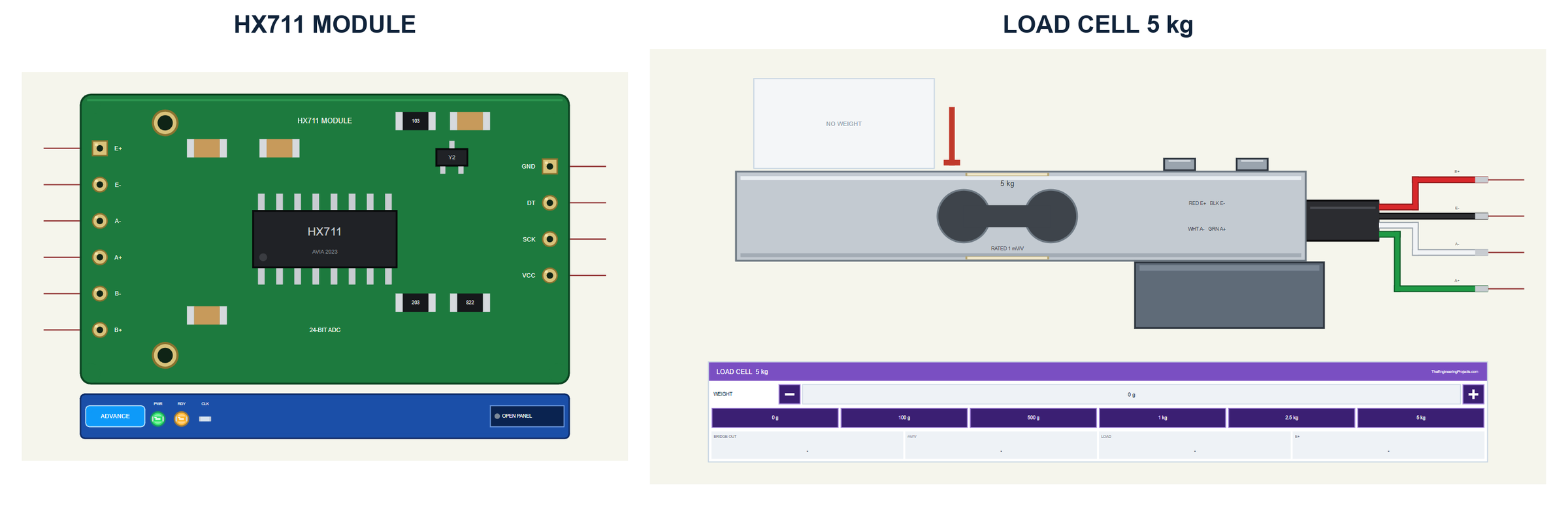
The parts look like the ones in your kit. The module is the green board with the HX711 in its SOP-16 package, the regulator's transistor, the resistors and capacitors, the two mounting holes and the gold pads of its two headers. The load cell is the silver bar with the double hole in its middle, its label with the capacity and the rated output, the two screws of the fixed end and the black cable with the red, black, white and green wires. A weight block sits on the loaded end and shows the weight you set.
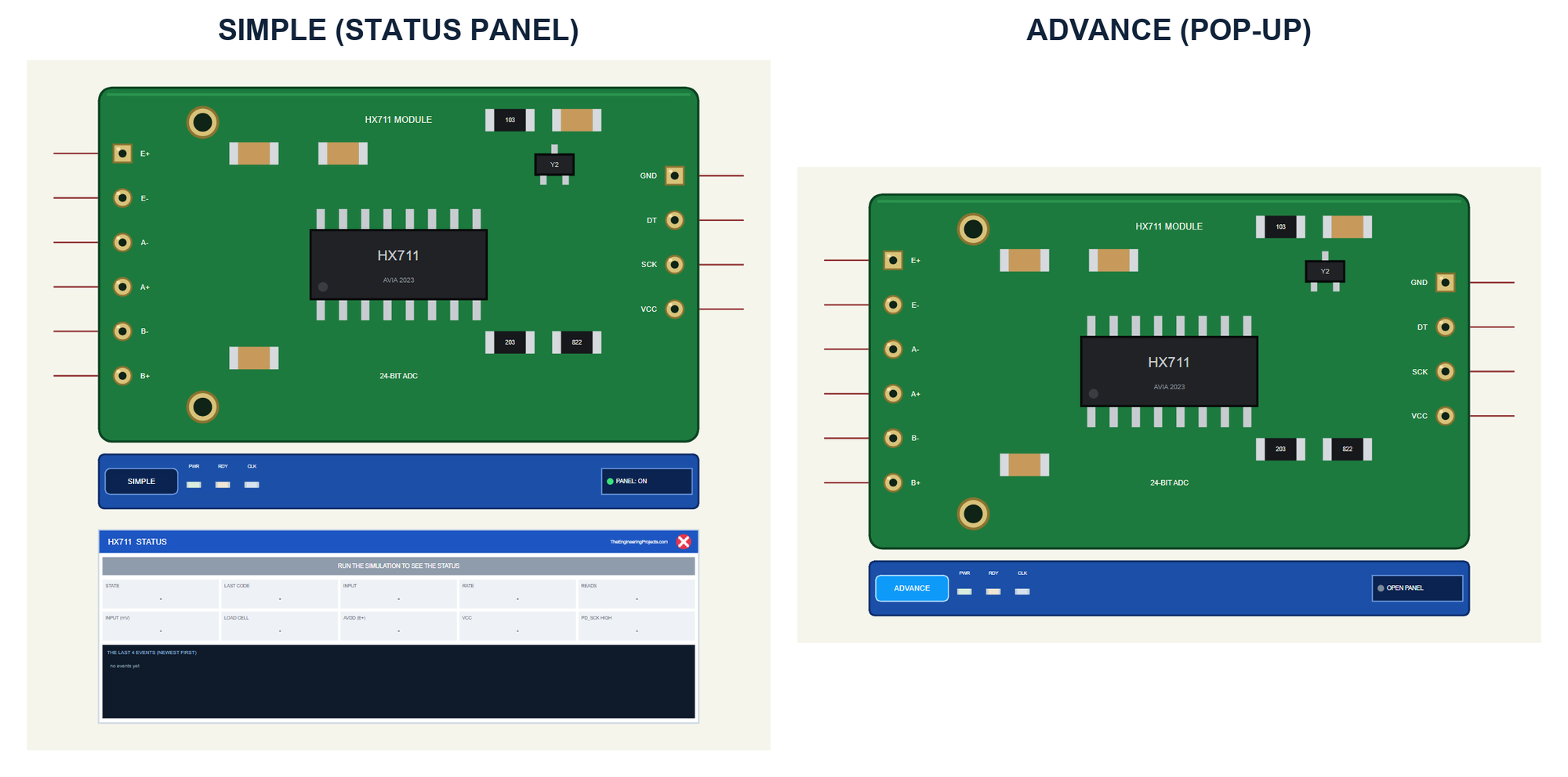
| Simple | Advance | |
|---|---|---|
| Device | HX711TEP | HX711ADVTEP |
| On the schematic | The module, its strip and the STATUS panel | The module and its strip |
| The weight | On the load cell's WEIGHT panel | The same, and in the pop-up |
| Status | Banner, 10 readouts, the last 4 events | A pop-up: Scale, Event log, Tests |
| Interaction | The red X, PANEL on the strip | The pop-up, OPEN PANEL on the strip |
Download HX711 Load Cell Library for Proteus
Click the button below to download HX711-Load-Cell-Library-for-Proteus-v1.0.zip (about 1.26 MB, without the C++ source code of the model):
HX711 Load Cell Library for Proteus V1.0: Arduino Weight Sensor- README.txt: the devices, installation, the demo, wiring, the test tools and real hardware.
- Proteus Library Files:
TEPHX711.LIBandArduinoV4TEP.LIBfrom our Arduino Library for Proteus V4.0. - Proteus Model Files:
TEPHX711.DLLandTEPARDUINO.DLL. - Proteus Simulation:
HX711-LoadCell-ArduinoUnoV4.pdsprj,HX711_Demo.hexand copies of the two DLLs. - Arduino Code:
HX711_Demo.ino. It needs the HX711 library by Bogdan Necula from the Library Manager of the Arduino IDE, only if you want to change the sketch.
No Proteus yet? Read How to Download and Install Proteus 7 and 8. New to libraries? Follow How to Install a New Library in Proteus.
How to Install HX711 Load Cell Library for Proteus
- Close Proteus and extract the whole zip file, for example to your Desktop.
- Copy the two files from Proteus Library Files into the LIBRARY folder of Proteus (usually
C:\Program Files (x86)\Labcenter Electronics\Proteus 8 Professional\LIBRARY). - Copy
TEPHX711.DLLandTEPARDUINO.DLLfrom Proteus Model Files into the MODELS folder. - Delete
TEPHX711.IDXfrom the LIBRARY folder if it is there. - Start Proteus, press P and search for HX711 or LOAD CELL.
Tip: keep the Proteus Simulation folder together, because the project needs its .hex file and the DLLs beside it. The library is tested in Proteus 8.5; Proteus 7 is not supported.
The HX711 Parts in Proteus
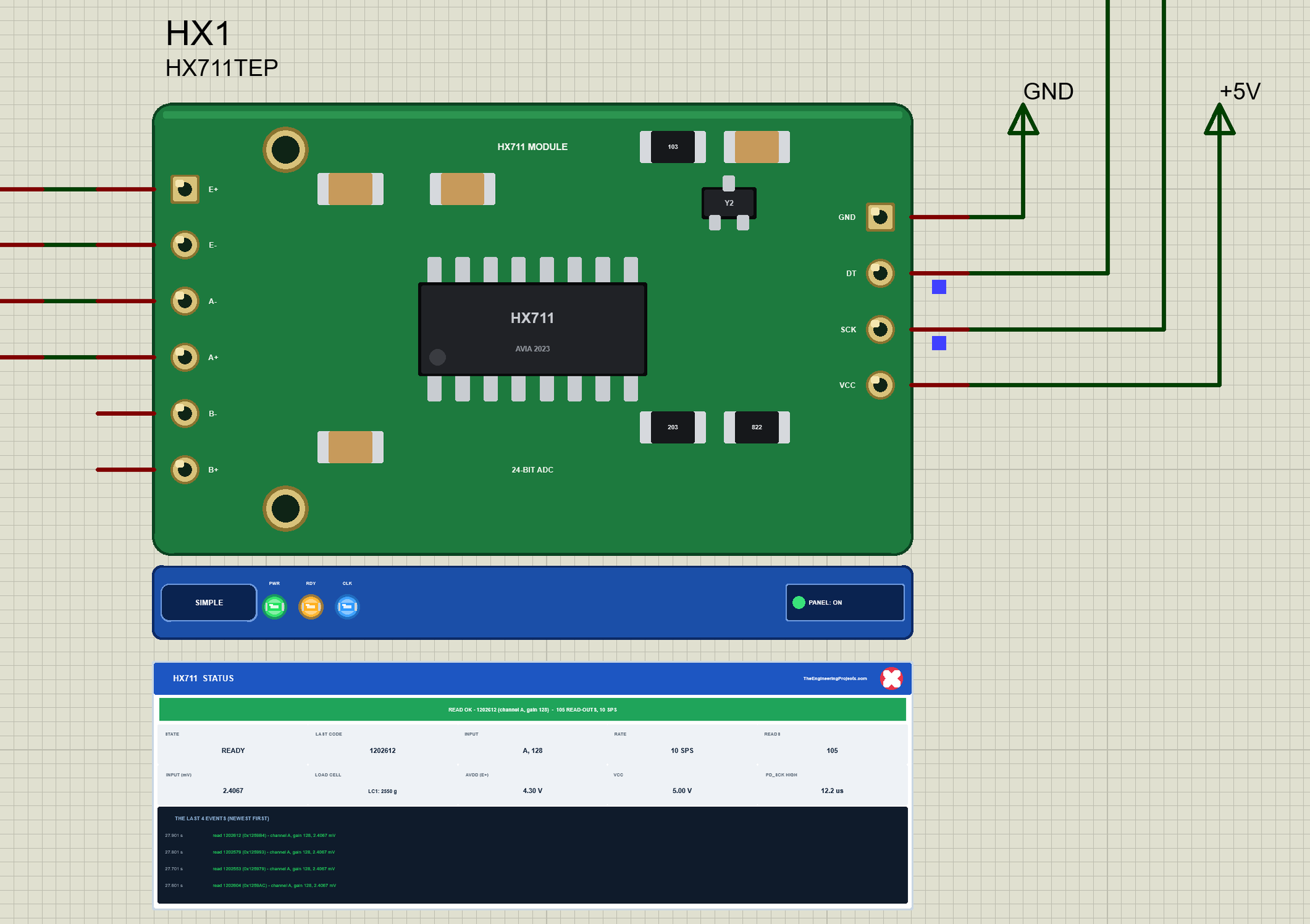
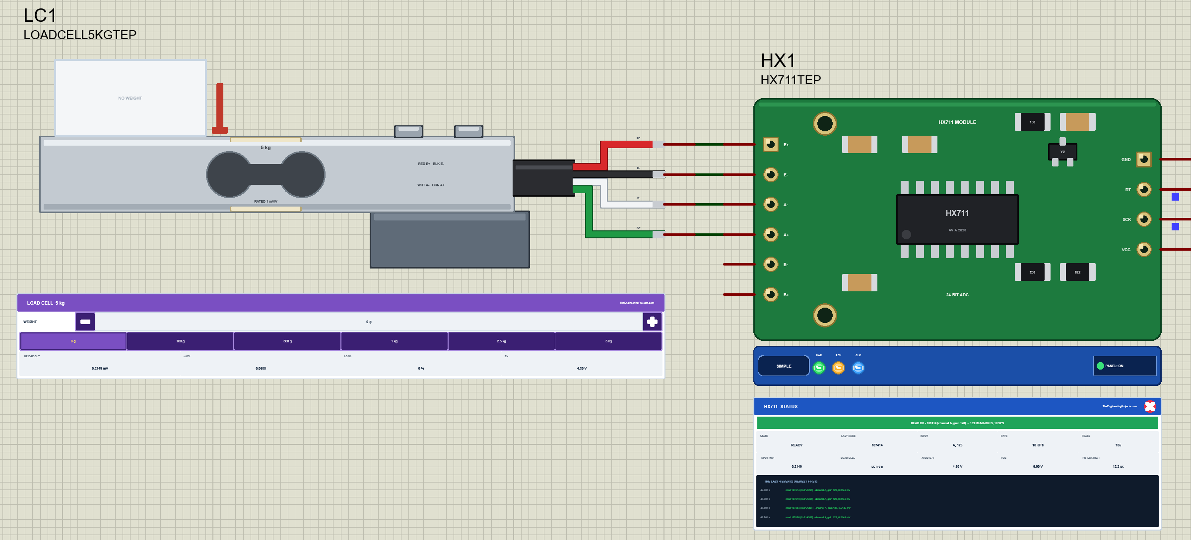
Under the module is the TEP strip with the SIMPLE or ADVANCE badge and three LEDs: PWR while VCC is there, RDY while DOUT is LOW (a result is ready) and CLK while the Arduino sends PD_SCK pulses. The strip, its LEDs and the panels are TEP additions; the real module has none of them.
The Simple device adds the STATUS panel. Its banner says what happened last, for example "READ OK - 1202612 (channel A, gain 128) - 105 READ-OUTS, 10 SPS", turns blue while the chip settles, grey while it is powered down and red with a warning. Ten readouts follow: the state, the last code, the input and its gain, the rate, the read-outs, the input in millivolts, the load cell on A+ and A- with its weight, AVDD on E+, VCC and the longest PD_SCK HIGH. At the bottom are the last four events.
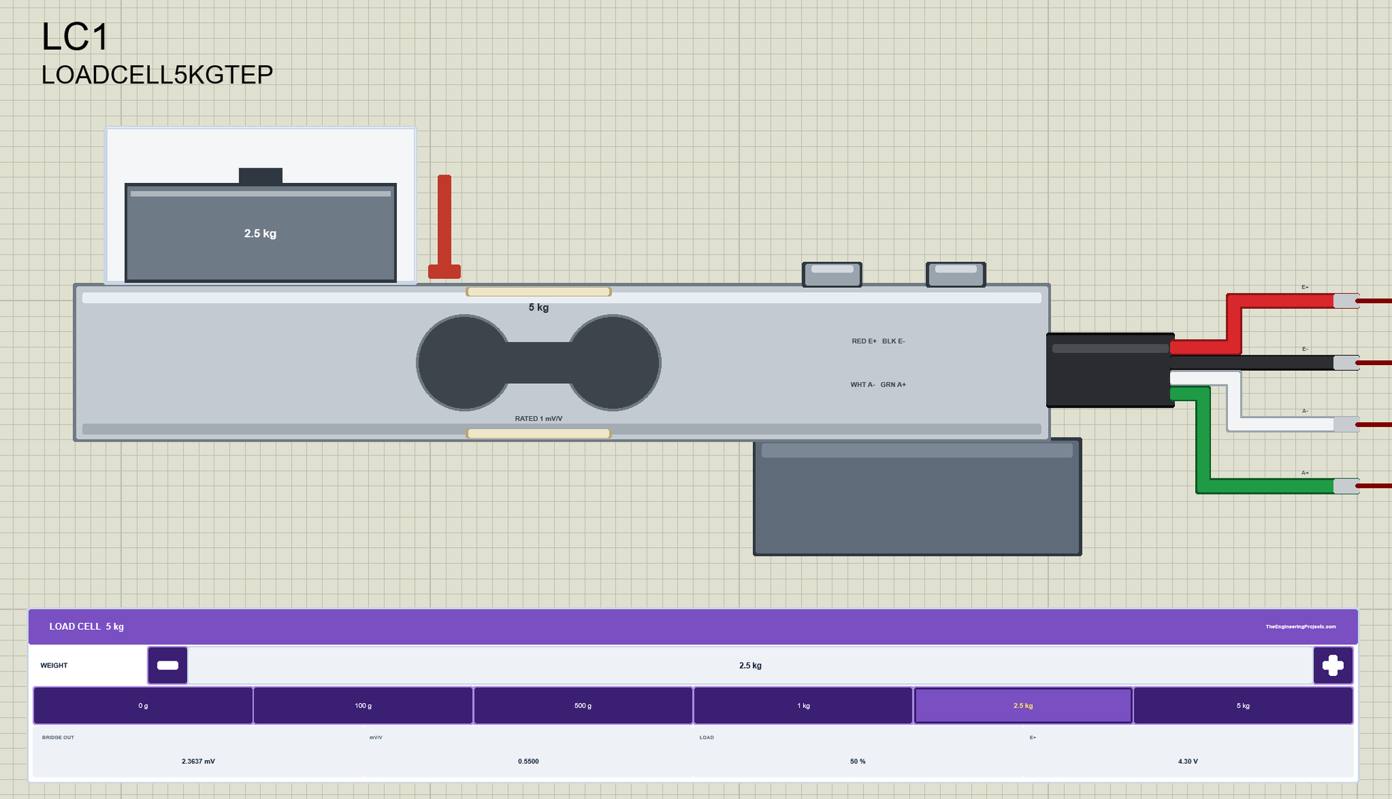
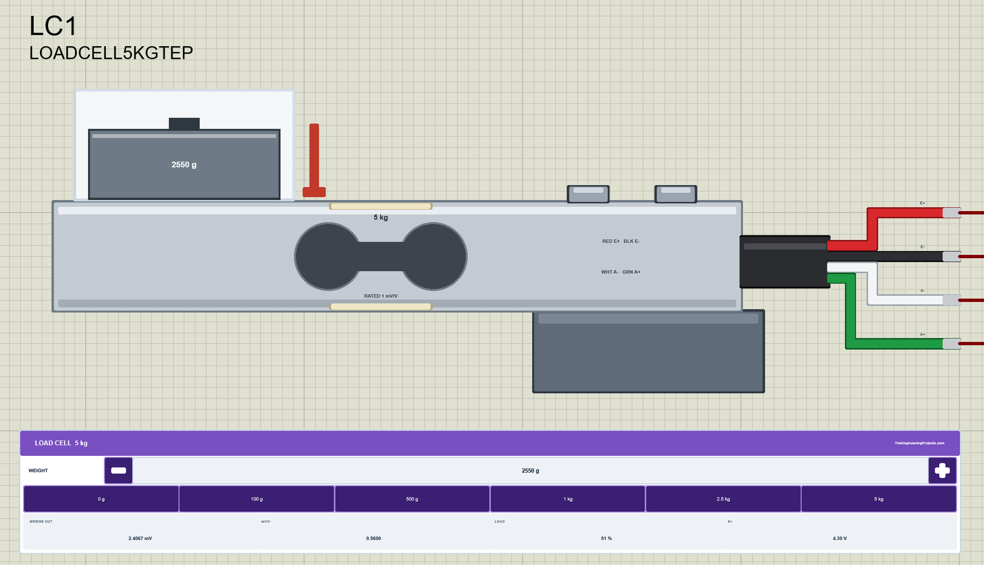
Every load cell has its own WEIGHT panel. The - and + buttons change the weight by 1 percent of the capacity a click (10, 50 or 200 g), and six presets put a typical weight on at once. Under them are four readouts: BRIDGE OUT, the voltage between A+ and A-, mV/V, the same per volt of excitation, LOAD in percent of the capacity and E+, the excitation from the HX711. Three properties set the start: WEIGHT in grams, ZERO, the zero balance in mV/V, and RATED, the rated output.
The red X closes the HX711's STATUS panel, and the PANEL button on the strip opens it again, so a big project stays readable:
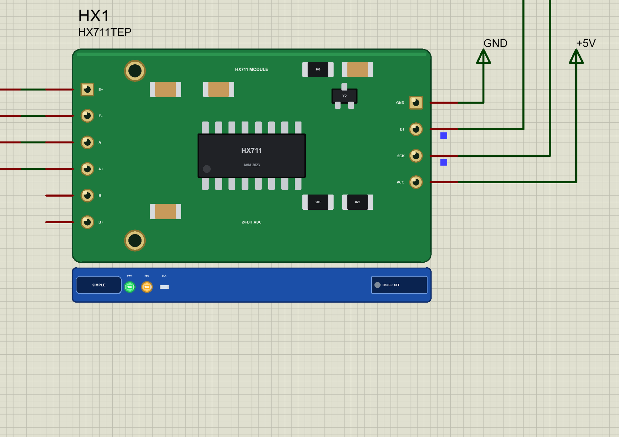
The Advance device keeps the schematic clean: only the module and its strip. Its live data opens in a pop-up window at Run, and the OPEN PANEL button brings the window back if you close it. The HX711 has two properties of its own: RATE, 10 or 80 samples a second, and NOISE, the converter's noise in counts (30 by default, 0 for none).
The Demo Circuit
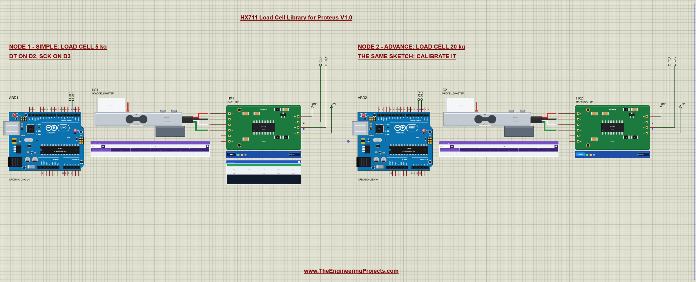
The demo project has two nodes. Each one is an Arduino UNO V4.0 from our Arduino UNO Library for Proteus V4.0 with an HX711 module on D2 (DT) and D3 (SCK) and a load cell on the module's channel A. Both UNOs run the same HX711_Demo.hex. Node 1 uses the Simple HX711 with a 5 kg cell, which fits the sketch's calibration factor; node 2 uses the Advance HX711 with a 20 kg cell, which you calibrate yourself.
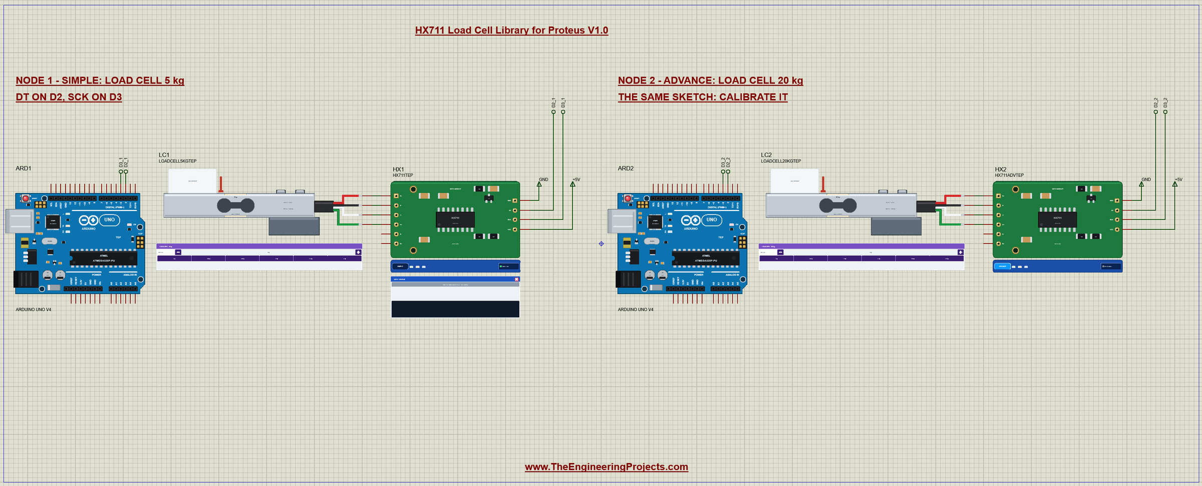
Wiring
| Load cell | HX711 | HX711 | Arduino UNO |
|---|---|---|---|
| red | E+ | VCC | 5V (3.3 V works too) |
| black | E- | GND | GND |
| white | A- | DT | D2 (any digital pin) |
| green | A+ | SCK | D3 (any digital pin) |
In Proteus the load cell's four wires go straight to the module's left header. DT and SCK reach their UNO through wires with net labels, D2_1 and D3_1 for node 1 and D2_2 and D3_2 for node 2, and VCC and GND go to the +5V and GND terminals. B- and B+ stay open, as on most real scales. The serial monitor needs no wires at all, because it is built into the UNO V4.0.
Node 1 Up Close
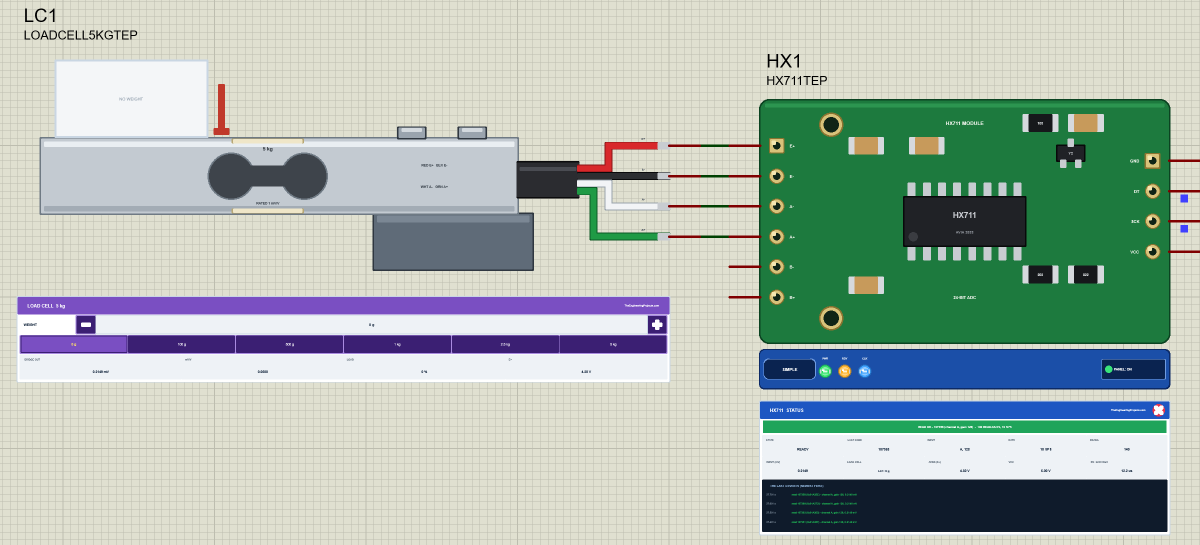
Here you see the whole chain: the bridge's red, black, white and green wires to E+, E-, A- and A+, and the module's GND, DT, SCK and VCC to the UNO. The LOAD CELL readout on the STATUS panel shows which cell sits on A+ and A-, so the pop-up and the tools can show its weight next to the code.
The Arduino Code
The demo sketch uses the HX711 library by Bogdan Necula (version 0.7.5), the most common library for the HX711. New to Arduino? Start with Arduino Tutorial for Beginners and Introduction to Arduino UNO. The sketch begins with the library:
#include <HX711.h>Then the two pins and the time between readings:
const uint8_t DT_PIN = 2;                      // the HX711's DT (DOUT)
const uint8_t SCK_PIN = 3;                     // the HX711's SCK (PD_SCK)
const unsigned long PERIOD = 1000;             // ms between two readings
In setup() the sketch starts the HX711 on channel A with gain 128, waits for the first result, sets the factor of a 5 kg cell and tares the empty scale:
  scale.begin(DT_PIN, SCK_PIN);                // channel A, gain 128
  if (!scale.wait_ready_timeout(1000)) Serial.println(F("No HX711 on D2 / D3"));
  scale.set_scale(429.5);                      // counts per gram of a 5 kg cell
  scale.tare(10);                              // the empty scale = 0 g
  Serial.print(F("Tare: offset ")); Serial.println(scale.get_offset());
tare(10) reads 10 results and stores their average as the offset, the code of the empty scale. A reading is read_average(5), the average of 5 results; the weight is the code minus the offset, divided by the factor. wait_ready_timeout() keeps the sketch from hanging when the HX711 sends no result:
void readWeight() {
  Serial.print('#'); Serial.print(++count);
  if (!scale.wait_ready_timeout(1000)) {       // DOUT stays HIGH: no result
    Serial.println(F("  no result - is the HX711 powered down?"));
    return;
  }
  const long raw = scale.read_average(5);
  const float grams = (raw - scale.get_offset()) / scale.get_scale();
  Serial.print(F("  ")); Serial.print(grams, 1); Serial.print(F(" g   raw "));
  Serial.println(raw);
}
The commands make the classic steps of a scale. CAL computes the factor from a known weight:
  } else if (!strncmp(s, "CAL", 3)) {          // put a known weight on, then CAL and its grams
    const long g = atol(s + 3);
    if (g <= 0) { Serial.println(F("CAL grams - with that weight on the cell")); return; }
    const float factor = scale.get_value(10) / g;
    scale.set_scale(factor);
    Serial.print(F("CAL ")); Serial.print(g); Serial.print(F(" g: "));
    Serial.print(factor, 2); Serial.println(F(" counts per gram"));
GAIN changes the gain on channel A. The new gain counts only after the next read-out, so the sketch reads once right away:
  } else if (!strncmp(s, "GAIN", 4)) {         // the next results at gain 64 or 128 (channel A)
    const int g = atoi(s + 4);
    if (g != 128 && g != 64) { Serial.println(F("GAIN 128 or 64")); return; }
    scale.set_gain(g);
    scale.read();                              // this read-out switches the HX711
    Serial.print(F("GAIN ")); Serial.print(g); Serial.println(F(": calibrate again (CAL)"));
OFF and ON power the HX711 down and up:
  } else if (!strcmp(s, "OFF")) {
    scale.power_down();
    Serial.println(F("OFF: power_down() - PD_SCK held HIGH"));
  } else if (!strcmp(s, "ON")) {
    scale.power_up();
    Serial.println(F("ON: power_up() - a result 400 ms later"));
The HEX file is in the package, so you do not need the Arduino IDE to run the demo. To change the sketch, install "HX711 Arduino Library" by Bogdan Necula from the Library Manager, open the sketch in the Arduino IDE and export the compiled binary, as in How to get the HEX file from Arduino. It needs 8,468 bytes of flash and 313 bytes of RAM.
The Serial Monitor
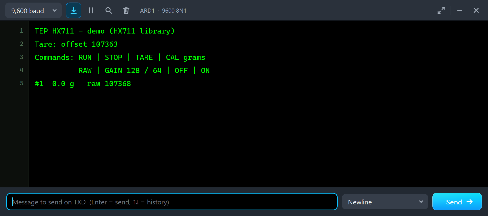
Both UNOs have the serial monitor built in, and it opens at Run. The screenshots use its Simple interface. Node 1 starts like this:
TEP HX711 - demo (HX711 library)
Tare: offset 107363
Commands: RUN | STOP | TARE | CAL grams
          RAW | GAIN 128 / 64 | OFF | ON
#1  0.0 g   raw 107368
The tare measured an offset of about 107,000 counts on the empty scale. That is the zero balance of the 5 kg cell, 0.05 mV/V, which is 5 percent of the 2,147,000 counts of a full load. After the tare the scale reads 0.0 g, and every line shows the weight and the raw code. Type a command in the monitor and press Enter: STOP stops the readings, RUN starts them again, RAW prints one raw code, and TARE, CAL, GAIN, OFF and ON are explained below.
Change the Weight
Now let's put a weight on the scale while the simulation runs. We clicked the 1 kg preset on LC1's WEIGHT panel with the mouse:
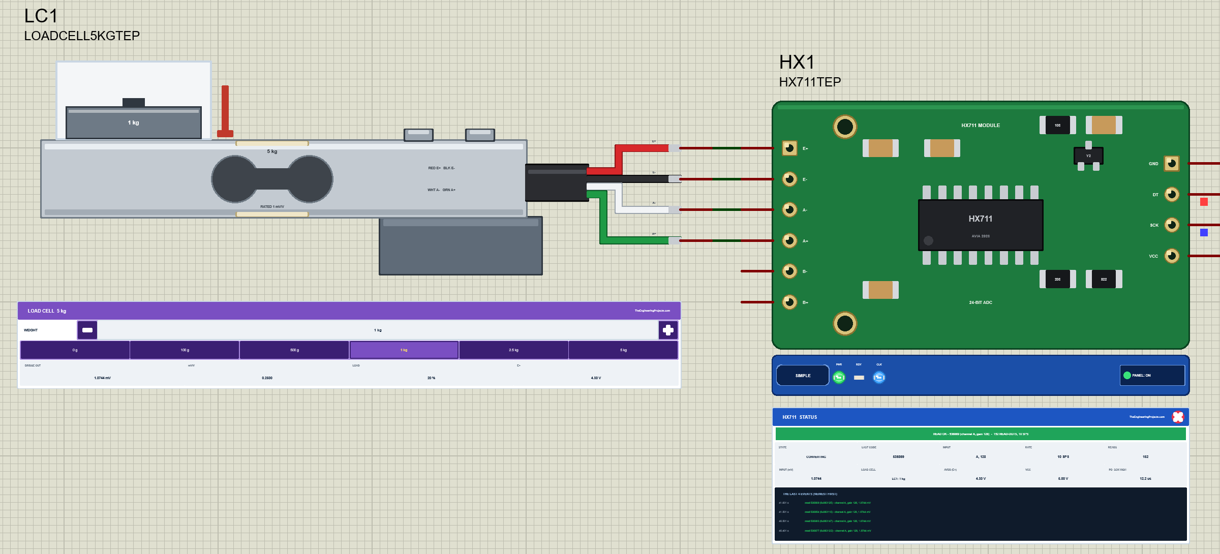
The bridge output follows at once, and the next reading shows the weight:
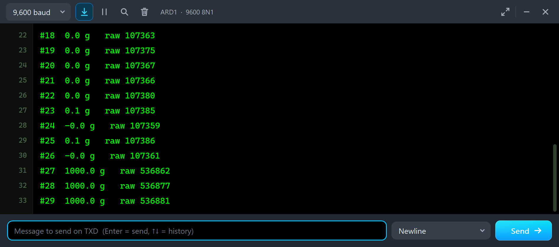
#26  -0.0 g   raw 107361
#27  1000.0 g   raw 536862
#28  1000.0 g   raw 536877
The code rose by about 429,500 counts, 429.5 counts per gram, exactly the factor in the sketch, so the scale reads 1000.0 g. The - and + buttons work the same way. Here we clicked the 2.5 kg preset, + twice and - once, 50 g a click on the 5 kg cell:
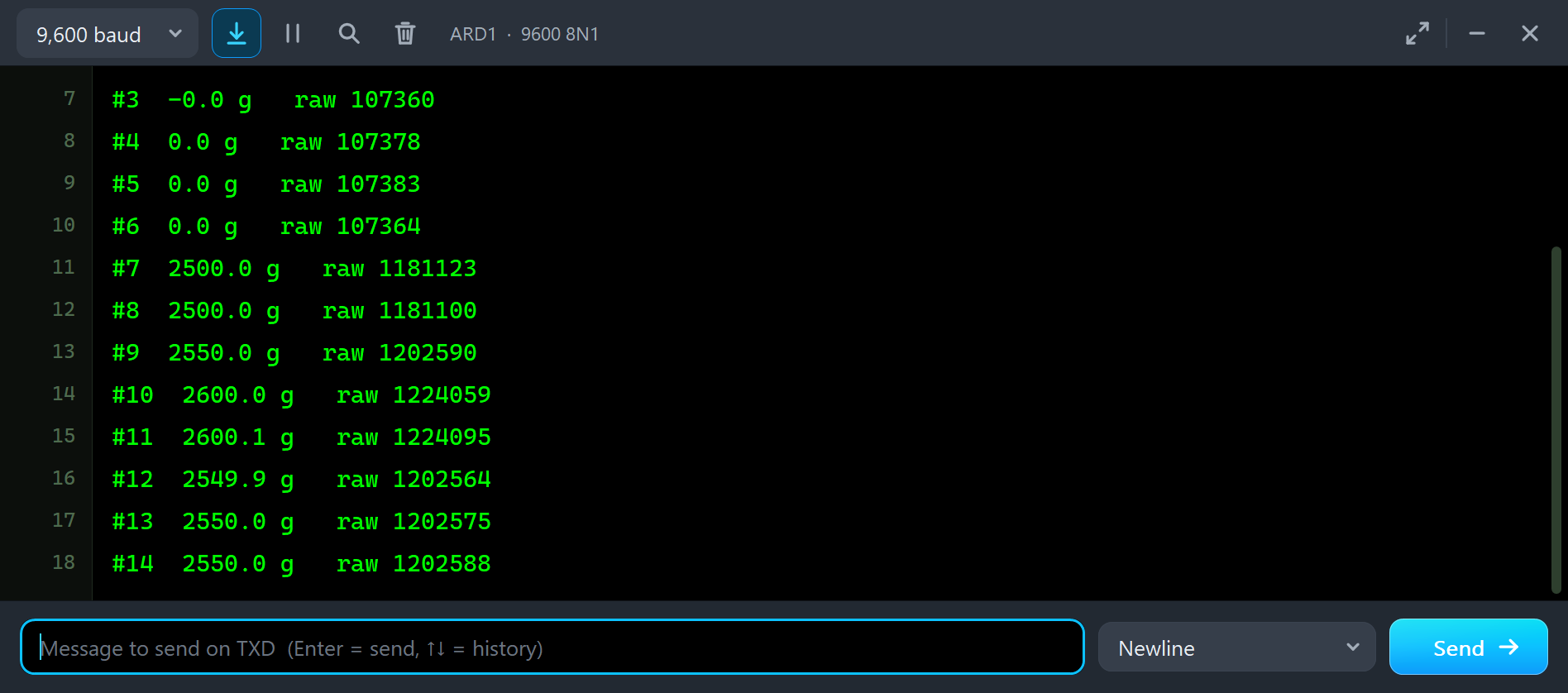
#8  2500.0 g   raw 1181100
#9  2550.0 g   raw 1202590
#10  2600.0 g   raw 1224059
#11  2600.1 g   raw 1224095
#12  2549.9 g   raw 1202564
#13  2550.0 g   raw 1202575
Each click moves the code by about 21,500 counts, 50 g x 429.5, and the next reading shows it: 2550, 2600, then 2550 again after the - click.
The Advance Pop-Up Window
At Run, the Advance HX711 opens its own window, HX711 Module, with the look of our TEP Serial Monitor Advance for Proteus. It has three tabs, Scale, Event log and Tests, plus Settings and Help behind the gear and question mark icons. The status bar at the bottom always shows the load, the input, the last code and the state.
The Scale Page
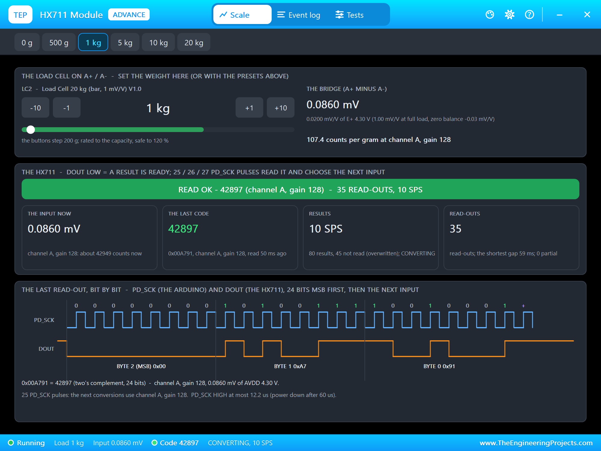
The toolbar carries the presets of the load cell on A+ and A-, here LC2 with 20 kg. The top card is the load cell: the weight with -10, -1, +1 and +10 steps (a step is 1 percent of the capacity, 200 g on this cell), a scale with the safe range, and the bridge: the millivolts between A+ and A-, the mV/V and the counts per gram at the current gain. The middle card is the HX711: the banner, the input now, the last code, the results and the read-outs.
The bottom card draws the last read-out, bit by bit: the Arduino's PD_SCK pulses, the HX711's DOUT, the 24 bits in three bytes, and the extra pulses that chose the next input. Under it the code is worked out: the hex value, the decimal value, the input and the millivolts, and the longest PD_SCK HIGH.
The Event Log
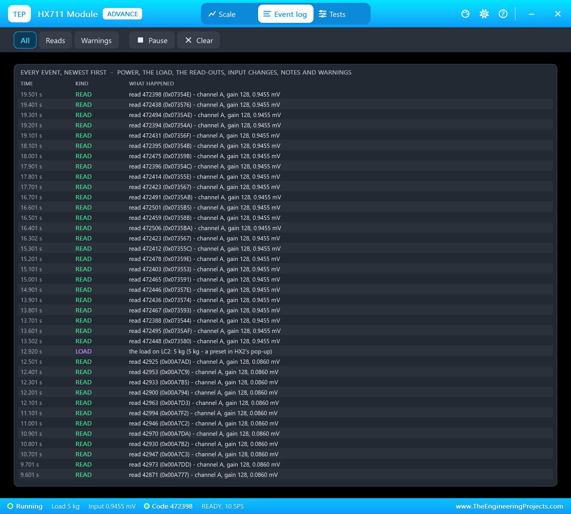
The Event log lists everything that happened, newest first: the power, the load changes with where they came from, the read-outs, the input changes, notes and warnings. You can see the rhythm of the demo in it: five read-outs 100 ms apart, the read_average(5) of one reading, then a pause until the next second. Filter the log by reads or warnings, pause it, or clear it.
Calibrate a Load Cell
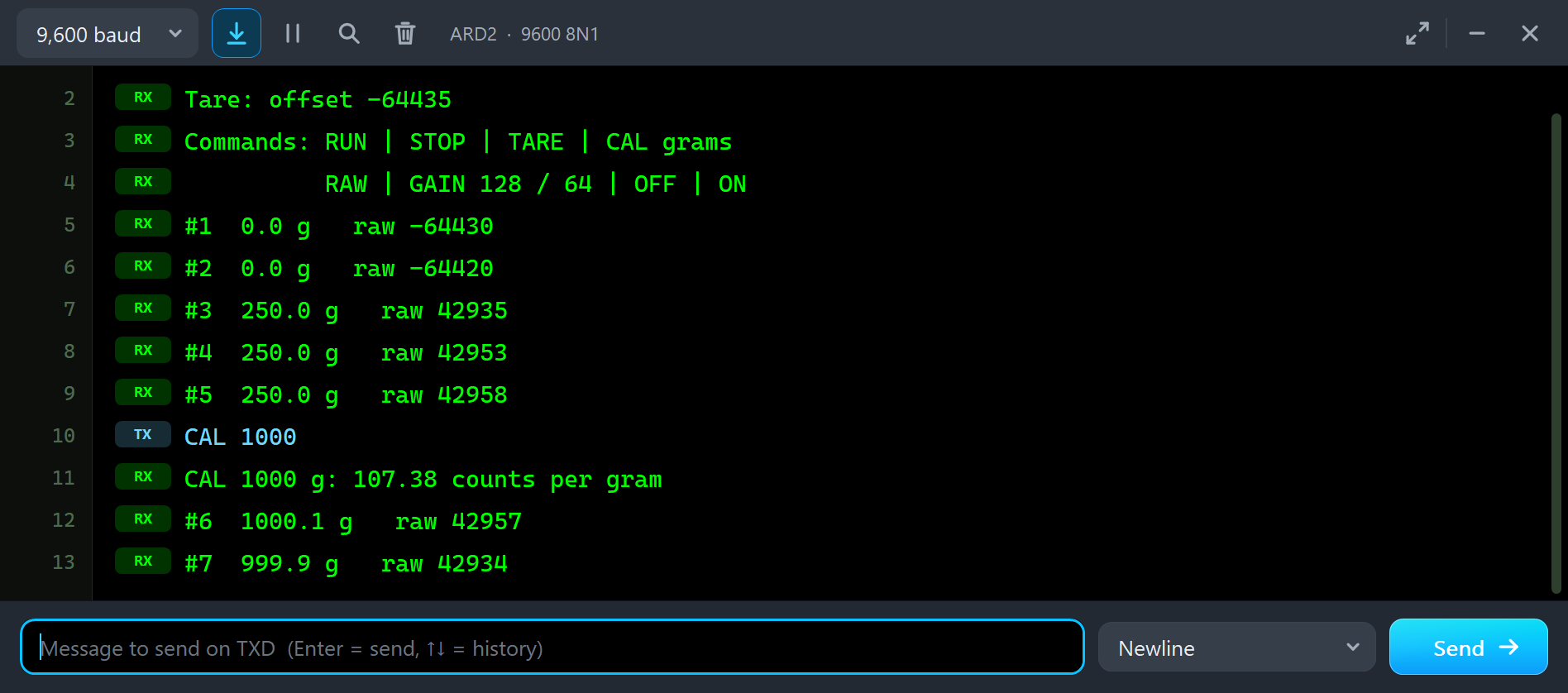
The sketch has the factor of a 5 kg cell, but node 2 has a 20 kg cell. We clicked 1 kg in HX2's pop-up, and node 2 read only 250.0 g: a 20 kg cell gives a quarter of the counts per gram of a 5 kg cell. This is what happens with every new cell, so the sketch has CAL. With the 1 kg still on, we typed CAL 1000:
#3  250.0 g   raw 42935
#4  250.0 g   raw 42953
#5  250.0 g   raw 42958
CAL 1000
CAL 1000 g: 107.38 counts per gram
#6  1000.1 g   raw 42957
#7  999.9 g   raw 42934
get_value(10) measured the code above the offset, and divided by 1000 g it gave 107.38 counts per gram, the factor of a 20 kg cell at 1 mV/V. From then on node 2 reads right. We clicked 5 kg in the pop-up, and the pop-up shows the whole chain at once:
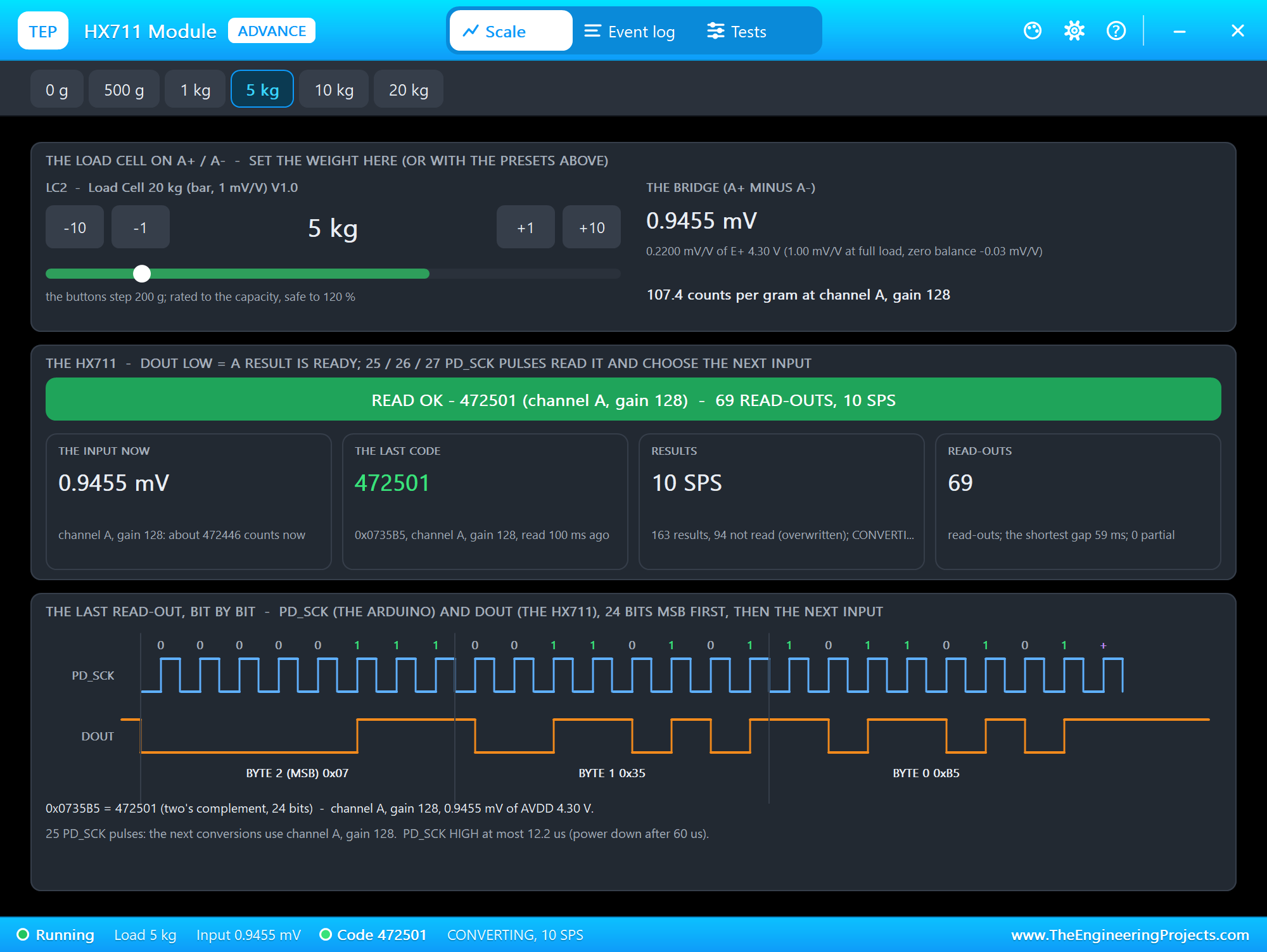
The bridge gives 0.9455 mV: 0.22 mV/V of E+ 4.30 V, because 5 kg is a quarter of the capacity (0.25 mV/V) and this cell has a zero balance of -0.03 mV/V. The code is about 472,500, and the bits on the bottom card spell it: 0x07, 0x35, 0xB5. The Calibration tool on the Tests page does the arithmetic for you:
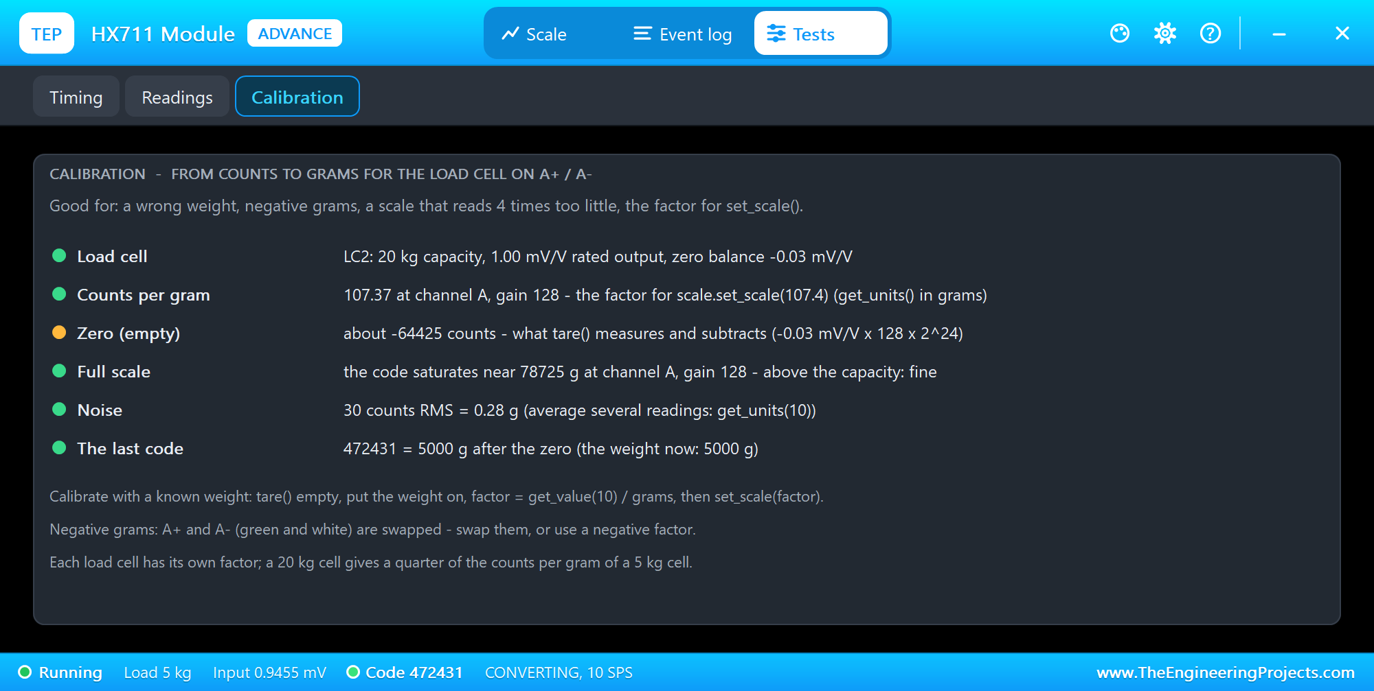
It shows the cell on A+ and A-, the counts per gram at the current gain, the factor for set_scale(), the zero that tare() measures and subtracts, the weight where the code saturates at 0x7FFFFF, the noise in grams and what the last code means in grams. Open it for a wrong weight, negative grams, or a scale that reads 4 times too little.
Classic HX711 Mistakes, Simulated
The demo can make the most common scale mistakes on purpose, so you can see what they look like before they happen on your desk. All of them were run in the final test.
A Tare With a Weight On
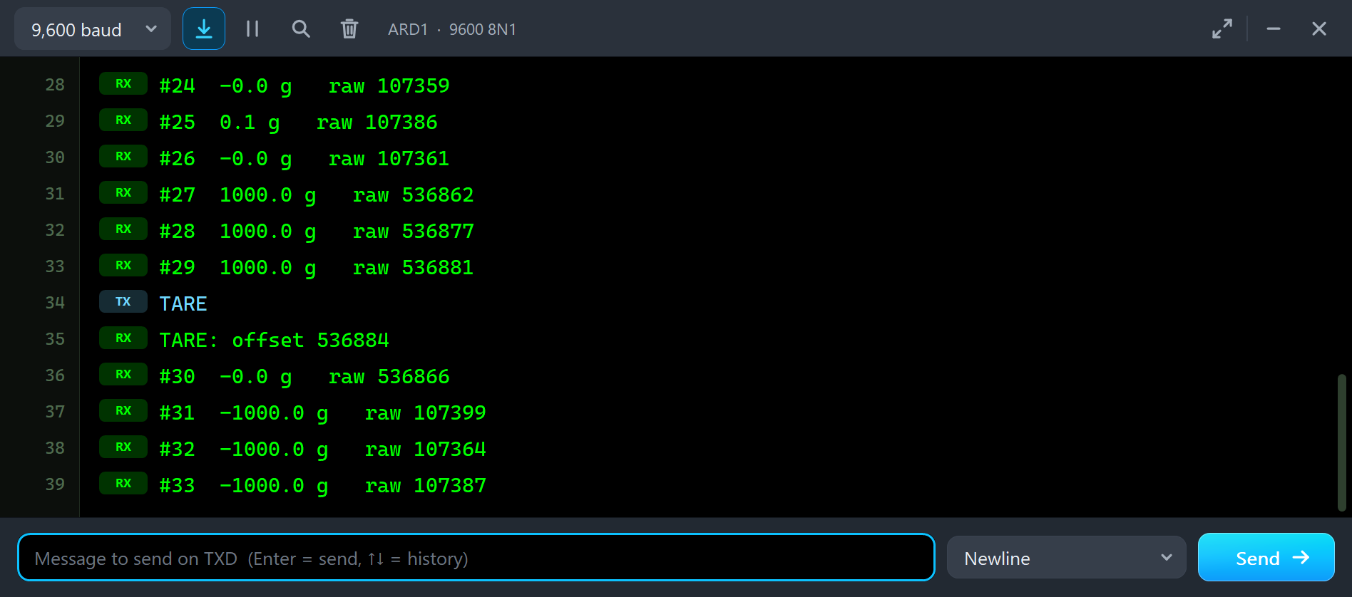
tare() stores whatever is on the scale as zero. With 1 kg on LC1 we typed TARE, and then clicked 0 g:
#29  1000.0 g   raw 536881
TARE
TARE: offset 536884
#30  -0.0 g   raw 536866
#31  -1000.0 g   raw 107399
#32  -1000.0 g   raw 107364
The empty scale now reads -1000.0 g. The fix is simple: tare with the scale empty, or with only the bowl on it. Negative grams can also mean that A+ and A- are swapped; then the weight goes down when you load the cell, and swapping the green and white wires, or a negative factor, fixes it.
A New Gain Without a New Calibration
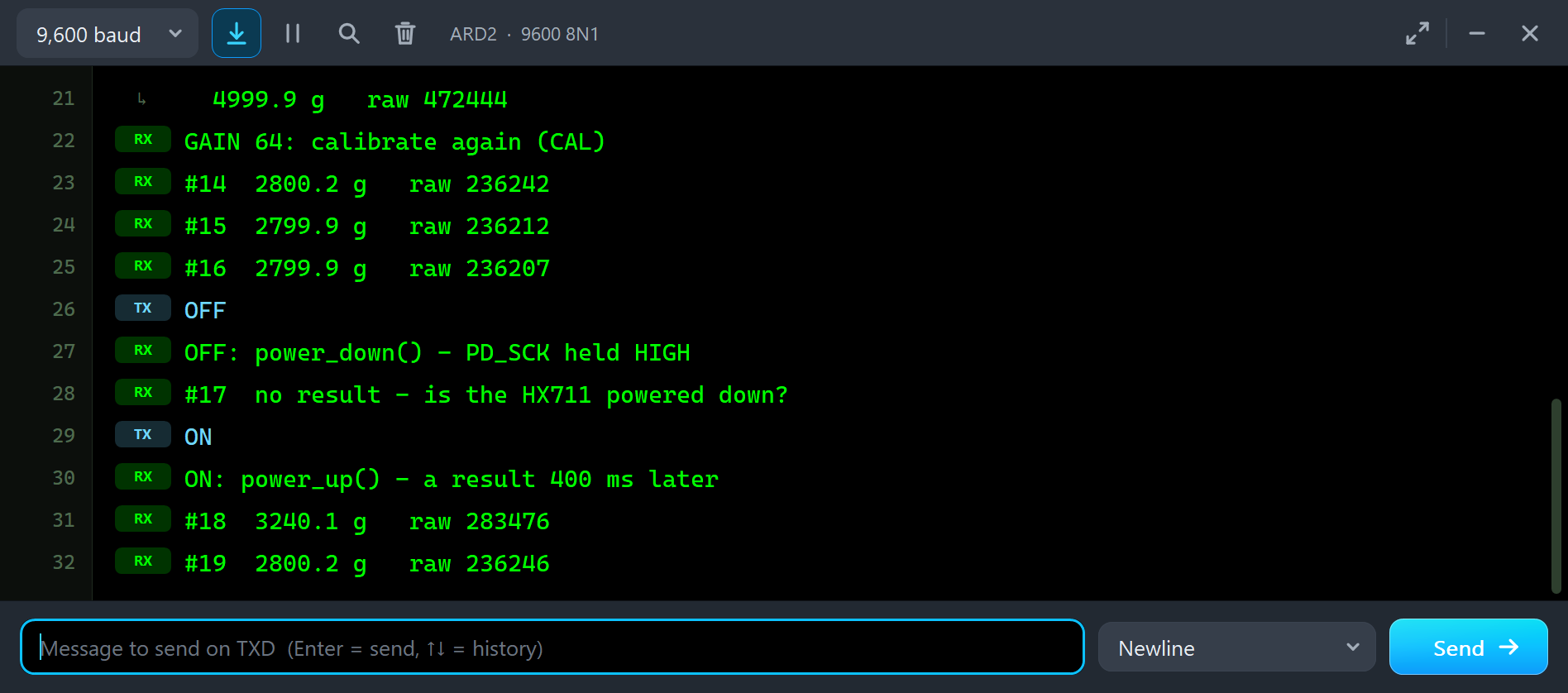
Channel A also works at gain 64, for example for a cell with a bigger output. We typed GAIN 64 on node 2 with 5 kg on its cell, then OFF and ON:
GAIN 64: calibrate again (CAL)
#14  2800.2 g   raw 236242
#15  2799.9 g   raw 236212
#16  2799.9 g   raw 236207
OFF
OFF: power_down() - PD_SCK held HIGH
#17  no result - is the HX711 powered down?
ON
ON: power_up() - a result 400 ms later
#18  3240.1 g   raw 283476
#19  2800.2 g   raw 236246
At gain 64 the codes are half as big, but the offset of the tare and the factor are still those of gain 128. So the weight shows as half, 2500 g, and the old offset is wrong too: the tare measured the zero balance of the cell, -0.03 mV/V, as -64,435 counts at gain 128, but at gain 64 it is only half of that, so about 32,000 counts, or 300 g, too many come back. Together that is the 2800 g on the monitor. After a change of the gain you must tare and calibrate again.
OFF holds PD_SCK HIGH and the HX711 powers down: DOUT stays HIGH, and the sketch says "no result". ON takes PD_SCK LOW, and the chip wakes up with channel A and gain 128, as the datasheet says. So the first result after the wake-up comes at gain 128 again; its read-out of 27 pulses sets gain 64, and the next results come 4 conversions later. The average of 5 mixed one result at gain 128 with four at gain 64, hence 3240.1 g, and the next reading is back at 2800.2 g. The Timing tool counts all of it:
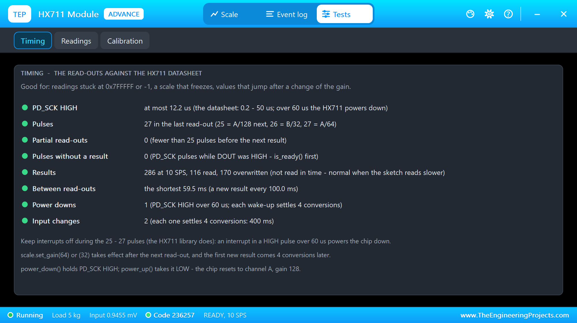
The Timing tool is the one to open for readings stuck at 0x7FFFFF or -1, a scale that freezes, or values that jump after a change of the gain. It measures the longest PD_SCK HIGH against the datasheet (50 us; power down after 60 us), the pulses of the last read-out, the partial read-outs, the pulses while no result was ready, the results read and overwritten, the shortest gap between read-outs, the power downs and the input changes. Overwritten results are normal: the HX711 converts 10 times a second, and the demo reads 5 of them every second.
The Readings Tool
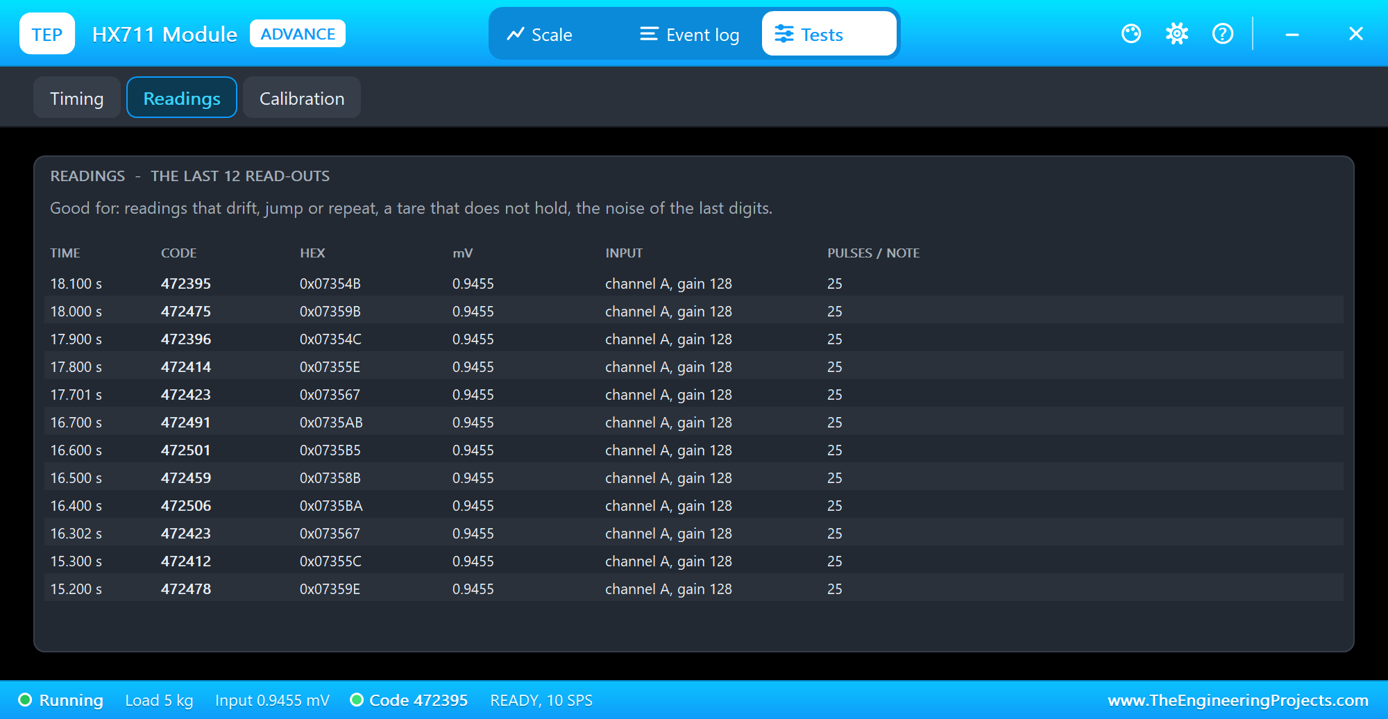
The Readings tool lists the last 12 read-outs with the time, the code in decimal and hex, the millivolts, the input and the pulses, or a note for a partial read-out. Open it for readings that drift, jump or repeat, or a tare that does not hold: the last digits move by a few dozen counts, the noise of the HX711 that the average of several readings smooths out.
The Simulation Log
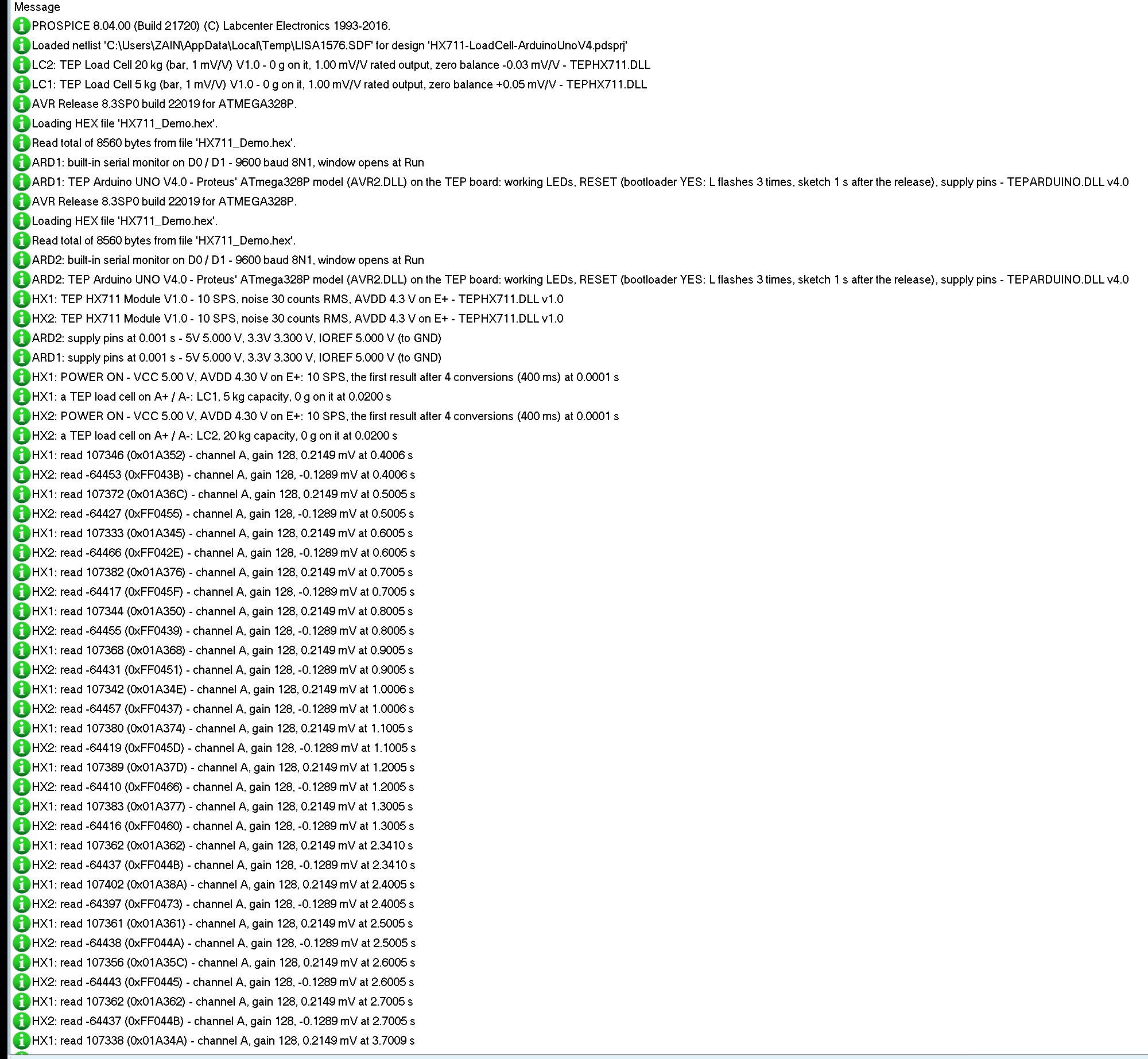
Every HX711 and load cell also writes to the simulation log of Proteus, with the exact simulation time. This part shows the start:
LC1: TEP Load Cell 5 kg (bar, 1 mV/V) V1.0 - 0 g on it, 1.00 mV/V rated output, zero balance +0.05 mV/V - TEPHX711.DLL
HX1: TEP HX711 Module V1.0 - 10 SPS, noise 30 counts RMS, AVDD 4.3 V on E+ - TEPHX711.DLL v1.0
HX1: POWER ON - VCC 5.00 V, AVDD 4.30 V on E+: 10 SPS, the first result after 4 conversions (400 ms) at 0.0001 s
HX1: a TEP load cell on A+ / A-: LC1, 5 kg capacity, 0 g on it at 0.0200 s
HX1: read 107346 (0x01A352) - channel A, gain 128, 0.2149 mV at 0.4006 s
HX2: read -64453 (0xFF043B) - channel A, gain 128, -0.1289 mV at 0.4006 s
Each part reports its setup when the simulation starts. The HX711 powers on at once, finds the TEP load cell on A+ and A-, and its first result comes at 0.4006 s: the 4 conversions of settling. The code of the empty 5 kg cell, 107346, is its zero balance of +0.05 mV/V; the 20 kg cell of node 2 has -0.03 mV/V, so its code is negative: -64453, or 0xFF043B in two's complement. Then the read-outs of the tare follow, 100 ms apart.
How the Model Works
The load cell is an analog part: four 1 kohm resistors between E+ and E-, unbalanced by the weight and the zero balance, in the SPICE simulation of Proteus. The HX711 drives E+ from its AVDD regulator, 4.3 V, or less when VCC is under 4.4 V, and at each conversion it reads the voltage between A+ and A- from the analog simulation. So the bridge really sees its excitation, and the result is ratiometric like the real chip's.
Proteus runs the Arduino's writes to PD_SCK as digital events, each with its exact time. The model takes every edge: a rising edge while DOUT is LOW starts a read-out, and 0.1 us after each rising edge the next bit appears on DOUT, from a simulator callback. A callback 60 us after each rising edge checks for a power down, and one 30 us after each falling edge ends a read-out of 25 to 27 pulses and sets the next input. The conversions run at exactly 10 or 80 a second, with the 4 conversions of settling after each change.
Troubleshooting
- "No HX711 on D2 / D3" or the sketch hangs: DT and SCK on the wrong pins, or no power on VCC (the strip's PWR LED is dark).
scale.read()waits forever without a chip; usewait_ready_timeout(). - The weight is wrong by a factor: calibrate with a known weight; every cell has its own factor.
- Negative grams: a tare with a weight on, or A+ and A- swapped.
- Not 0 g with an empty cell: tare; that is the zero balance of the cell.
- The weight jumps after a change of the gain: tare and calibrate again at the new gain.
- Stuck at one value or "no result": the HX711 is powered down (PD_SCK HIGH); call
power_up(). - No part, no reading at all or no monitor: TEPHX711.DLL or TEPARDUINO.DLL is missing from MODELS and the project folder; a closed monitor opens again with a click on the UNO's USB port.
Things to Know Before Building a Real Scale
- Mounting: screw the cell's fixed end to the base and the loaded end (the arrow) to the plate, each with a spacer; nothing may touch the bar between the screws.
- Calibration: every cell has its own factor and zero; calibrate with a known weight near the weights you will measure.
- Noise: average several readings, keep the wires short and twisted, and give the module a clean 5 V.
- Creep and temperature: a real cell drifts a little under a constant load and with the temperature; the model does not.
- Modules: most run at 10 samples a second (RATE to GND); on some cheap boards E- and GND are wired differently.
- For an HX711 on a Raspberry Pi, read our Interface Weight Sensor HX711 with Raspberry Pi 4.
Limitations of the Simulation
- Not modelled: creep, hysteresis, temperature drift and non-linearity of the cell (the bridge follows the weight at once and exactly), the HX711's offset and gain errors and the tolerance of its oscillator (exactly 10 or 80 conversions a second), the mechanics of the mounting, and the module's RATE pin (the property RATE instead).
- The strips, their LEDs and the panels are TEP additions.
- The models are our own, written from the HX711 datasheet and the data sheets of the load cells. This library is not made or endorsed by Avia Semiconductor, the author of the HX711 library, the makers of these modules and load cells or Labcenter.
- Licences: the demo sketch uses the HX711 library 0.7.5 by Bogdan Necula (MIT), which is not shipped; install it from the Library Manager. The demo's HEX file contains it and the Arduino AVR core 1.8.6 with LGPL-licensed code; the licence texts and the source links are in the README.
- Tested in Proteus 8.5 in October 2026 (the demo as shipped on two Arduino UNO V4.0 boards with their built-in monitors: the tare and the readings on both nodes, the presets and the - / + buttons with the mouse, CAL 1000, TARE with a weight on, GAIN 64, OFF and ON, the red X and PANEL, the pop-up and the three tools; 56.0 s of simulation took 112 s, about 0.5 x real time with the pop-up and both monitors open). Proteus 7 is not supported.
So, that was all about the HX711 Load Cell Library for Proteus V1.0. I hope the bridge, the 24-bit codes, the tare and the calibration factor are clear now, so your scale reads the right weight from the first run. If you use the HX711 Load Cell Library for Proteus in a project, please share it in the comments or in our forum, and if you have any questions, ask in the comments and I will help you out. Till the next tutorial, take care and have fun!