Hello friends, I hope you all are doing great. Today, I am going to share the new I2C LCD 16x2 Library for Proteus V1.0. The I2C LCD 16x2 is the same blue or yellow-green 1602 character LCD you know, with a small black I2C backpack soldered to its back. Instead of six or more wires, it needs only four: GND, VCC, SDA and SCL. That is why it is the LCD most of us use with an Arduino today. With this I2C LCD 16x2 Library for Proteus, your sketch talks to an LCD that behaves like the real module: the I2C address, the contrast trimmer on the backpack, the backlight jumper, and the real HD44780 behind it.
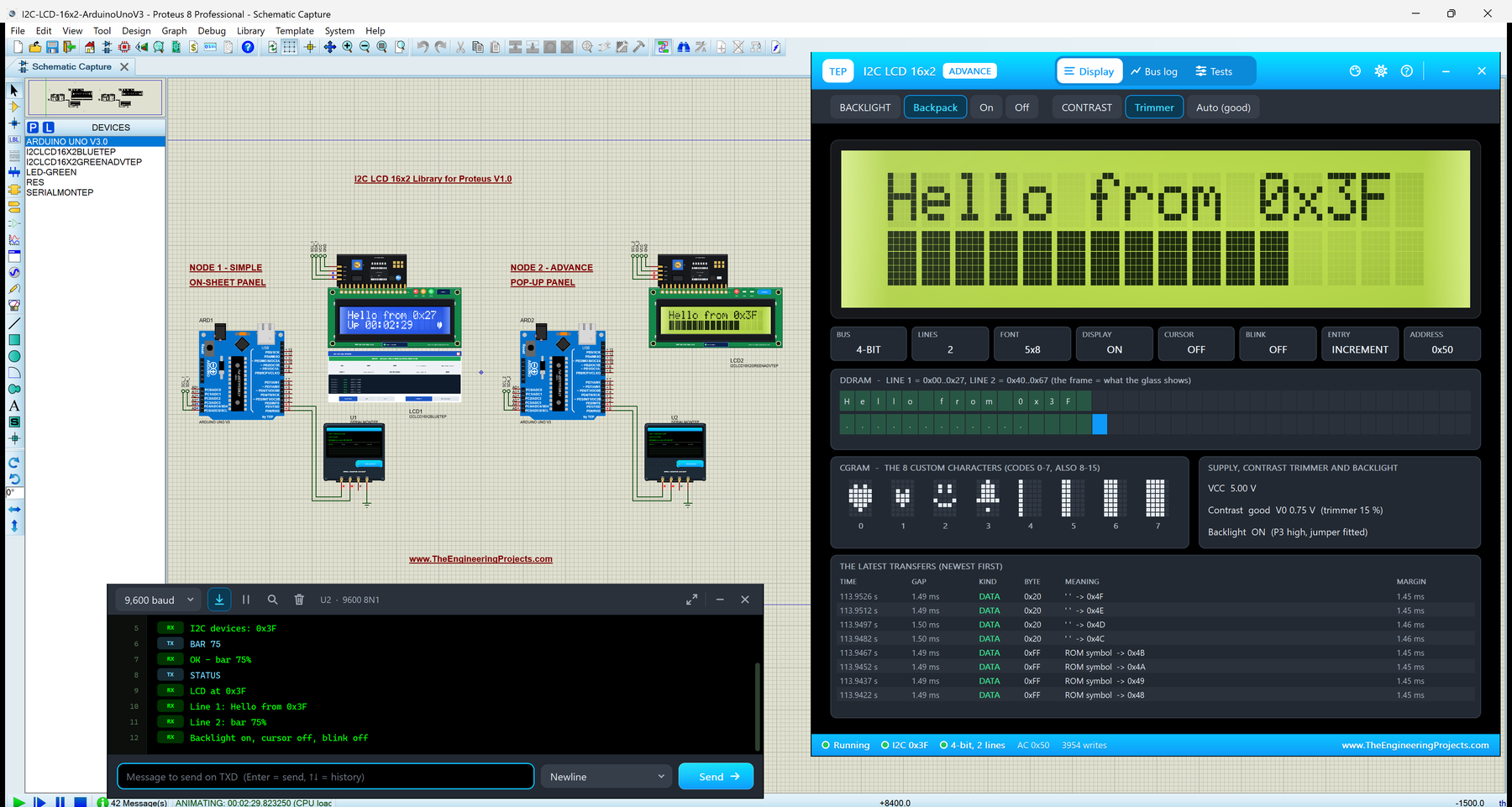
This is the second library of our LCD series, after the LCD 16x2 Library for Proteus V3.0, and it is our own model of the whole module: the PCF8574 I2C port expander of the backpack and the HD44780 controller of the LCD. You get four devices: a blue and a yellow-green LCD, each as I2C LCD 16x2 Simple, with a live STATUS panel on the schematic, and I2C LCD 16x2 Advance, with a pop-up window, a bus log and four LCD test tools, among them a new I2C bus tool. The demo runs the popular LiquidCrystal_I2C library on two Arduino UNOs, one LCD at 0x27 and one at 0x3F, with the Simple interface of our TEP Serial Monitor.
NOTICE: This library is very special to our team. We did not just draw a backpack on an LCD: we wrote the PCF8574 I2C chip ourselves, wired it to our HD44780 model exactly like the real backpack, and made the trimmer, the jumper and the address pads clickable. It took our team a lot of hard work and many test runs. Your feedback is the fuel that keeps us going, so please tell us what you think in the comments below or in the LCD Library board of our forum. And if our free libraries help you, you can buy us a coffee. So, let's get started with the I2C LCD 16x2 Library for Proteus V1.0:
What is an I2C LCD 16x2?
An I2C LCD 16x2 is a normal 16x2 character LCD (2 lines of 16 characters, each 5x8 dots, driven by the HD44780 controller) plus an I2C backpack: a small board of about 41 x 19 mm soldered to the LCD's 16-pin header. On the backpack sit a PCF8574T chip, a blue contrast trimmer, a LED jumper for the backlight, three address pads A0, A1 and A2, and a 4-pin header: GND, VCC, SDA, SCL. For the LCD itself, read our Introduction to 16x2 LCD Module.
The PCF8574 is an I2C port expander: it has 8 output pins, and the Arduino sets all 8 at once by sending one byte over I2C. The backpack wires those 8 pins to the LCD's RS, RW, E, the backlight and D4 to D7. So the LCD still runs on its 4-bit bus, but the bus now comes from the PCF8574 instead of six Arduino pins.
The I2C LCD 16x2 at a Glance
| Feature | Value |
|---|---|
| Display | 2 lines x 16 characters, each 5x8 dots (HD44780 controller) |
| Interface | I2C: SDA and SCL (A4 and A5 on an Arduino UNO), plus GND and VCC |
| Chip on the backpack | PCF8574T (addresses 0x20 - 0x27) or PCF8574AT (0x38 - 0x3F) |
| Default address | 0x27 (PCF8574T) or 0x3F (PCF8574AT): all three pads open |
| Supply | 5 V on VCC |
| Contrast | The blue trimmer on the backpack |
| Backlight | Switched by the PCF8574 (P3) through a transistor; the LED jumper must be fitted |
| Speed | About 1.5 ms per character at 100 kHz with LiquidCrystal_I2C |
| Arduino library | LiquidCrystal_I2C (Library Manager) and Wire |
Terms You Will See in This Article
| Term | Meaning |
|---|---|
| I2C | A two-wire bus: SDA carries the data, SCL the clock; many devices share it, each with its own address |
| Address | The 7-bit number a device answers to, written in hex (0x27) |
| ACK / NACK | After each byte the receiver pulls SDA low (ACK) or not (NACK); nobody at an address means NACK |
| PCF8574 | The I2C chip on the backpack: one byte in, 8 output pins (P0 - P7) |
| Port byte | The byte the Arduino writes to the PCF8574; each bit is one pin |
| Pull-up | A resistor that holds SDA and SCL high; I2C devices only pull the lines low |
| Trimmer | The small blue pot on the backpack that sets the contrast (V0) |
| DDRAM / CGRAM | The LCD's character memory / its 8 own characters |
How the PCF8574 Backpack Works
One Byte, Eight Pins
The backpack connects the PCF8574's pins like this: P0 = RS, P1 = RW, P2 = E, P3 = the backlight and P4 to P7 = D4 to D7. The LCD's D0 to D3 stay unconnected, so the LCD always runs in 4-bit mode. When the Arduino writes the byte 0x4D, for example, the pins become RS 1, RW 0, E 1, backlight 1 and D7 to D4 = 0x4. LiquidCrystal_I2C uses exactly this wiring, which is why it works with almost every blue backpack.
Three I2C Writes for Every Half Byte
The LCD takes a half byte (a nibble) when E falls. With a backpack, the sketch cannot pulse E directly, so LiquidCrystal_I2C sends three port bytes for each nibble: the data, the data with E high, and the data with E low again. A character is two nibbles, so it costs six I2C transactions. At the standard 100 kHz, that is about 1.5 ms per character, roughly five times slower than an LCD wired with six pins. Our Speed tool measures exactly this, and our bus log shows every port byte.
The I2C Address
A PCF8574T answers at 0x20 to 0x27, a PCF8574AT at 0x38 to 0x3F. The three pads A0, A1 and A2 choose the address: an open pad is a 1 and a bridged pad (a blob of solder across it) a 0. A new backpack has all pads open, so it is 0x27 or 0x3F, depending on the chip. If your sketch uses 0x27 but your backpack is 0x3F, the LCD just stays blank. That is the second most common I2C LCD problem, and our model shows it clearly.
The Contrast Trimmer and the LED Jumper
The blue trimmer is a 10k pot between VCC and GND, its wiper on the LCD's V0 pin. Turned one way, the characters fade out; turned the other way, the empty dots turn dark too. A new module can come with any setting, which is why the most common I2C LCD problem is "nothing on the screen": the trimmer. The backlight is switched by P3 through a transistor, and the two-pin LED jumper must be fitted, or the backlight stays off whatever the sketch does.
What's New in I2C LCD 16x2 Library for Proteus V1.0
Here is what the first version brings:
- Our own PCF8574 model inside
TEPLCD.DLL: the I2C slave with its address, ACK, port writes and reads, wired to our HD44780 model exactly like the real backpack. - Clickable backpack parts: the contrast trimmer, the LED jumper and the A0 - A2 address pads work while the simulation runs.
- A WRONG ADDRESS warning: when the sketch writes to another address, the panel says so in red.
- Four devices in
TEPI2CLCD16X2.LIB: blue and yellow-green, each Simple and Advance. - Four LCD test tools on the Advance: Init check, I2C bus, Speed and Characters.
- A two-UNO demo with LiquidCrystal_I2C: one sketch that finds the address itself, one LCD at 0x27 and one at 0x3F, and Serial commands such as SCAN and LIGHT ON / OFF.
- A compact package: about 1.42 MB, without the C++ source code.
The model file TEPLCD.DLL is shared with our LCD 16x2 V3.0 library and runs its devices too. If you have both, keep this newer DLL.
I2C LCD 16x2 Simple vs I2C LCD 16x2 Advance
All four devices share one model and the same module. They differ in the glass colour and in where you see the extras:
| Device | Name in Pick Devices | Glass | Extras |
|---|---|---|---|
| I2CLCD16X2BLUETEP | I2C LCD 16x2 V1.0 Blue - Simple | Blue, white characters | STATUS panel on the sheet |
| I2CLCD16X2BLUEADVTEP | I2C LCD 16x2 V1.0 Blue - Advance | Blue, white characters | Pop-up window and tools |
| I2CLCD16X2GREENTEP | I2C LCD 16x2 V1.0 Yellow-green - Simple | Yellow-green, dark characters | STATUS panel on the sheet |
| I2CLCD16X2GREENADVTEP | I2C LCD 16x2 V1.0 Yellow-green - Advance | Yellow-green, dark characters | Pop-up window and tools |
Pick a Simple LCD when you want to see the LCD's state and its I2C address right on the schematic. Pick an Advance LCD when the schematic is crowded, or when you want the bus log and the I2C bus tool. The backpack's trimmer, jumper and pads work on all four.
Download I2C LCD 16x2 Library for Proteus
Click the button below to download I2C-LCD-16x2-Library-for-Proteus-v1.0.zip (about 1.42 MB, without the C++ source code):
I2C LCD 16x2 Library for Proteus V1.0- README.txt: a detailed guide to the files, the wiring, the backpack, the test tools and real hardware.
- Proteus Library Files:
TEPI2CLCD16X2.LIB(all four devices),TEPSERIALMON.LIBand our Arduino UNO libraryArduinoV3TEP.LIB/ArduinoV3TEP.IDX. - Proteus Model Files:
TEPLCD.DLLandTEPSERIALMON.DLL. - Proteus Simulation:
I2C-LCD-16x2-ArduinoUnoV3.pdsprj,I2C_LCD_16x2_Demo.hex(both UNOs run it) and copies of both DLLs. - Arduino Code:
I2C_LCD_16x2_Demo.ino, the demo sketch. It needs the "LiquidCrystal I2C" library by Frank de Brabander from the Library Manager.
Want all four LCDs? This LCD is also part of our LCD Library for Proteus V3.0: the LCD 16x2, LCD 20x4, I2C LCD 16x2 and I2C LCD 20x4 in one library (16 parts, one DLL), with a demo in which one Arduino UNO drives all four.
No Proteus yet? Read How to Download and Install Proteus 7 and 8. New to libraries? Follow How to Install a New Library in Proteus.
How to Install I2C LCD 16x2 Library for Proteus
- Close Proteus and extract the whole zip file to a normal folder, for example your Desktop.
- Copy the four files from Proteus Library Files into the LIBRARY folder, usually
C:\Program Files (x86)\Labcenter Electronics\Proteus 8 Professional\LIBRARY(on some PCsC:\ProgramData\Labcenter Electronics\Proteus 8 Professional\LIBRARY; use the folder that already holds Proteus's own .LIB files). - Copy
TEPLCD.DLLandTEPSERIALMON.DLLfrom Proteus Model Files into the MODELS folder. - Delete
TEPI2CLCD16X2.IDXfrom the LIBRARY folder if there is one; Proteus makes a new index. - Start Proteus, press P and search for I2CLCD16X2. You get the four devices.
Tip: the demo project needs the .hex file and the two DLLs beside it, so keep the Proteus Simulation folder together. The library was tested in Proteus 8.5; Proteus 7 is not supported.
The I2C LCD 16x2 Board in Proteus
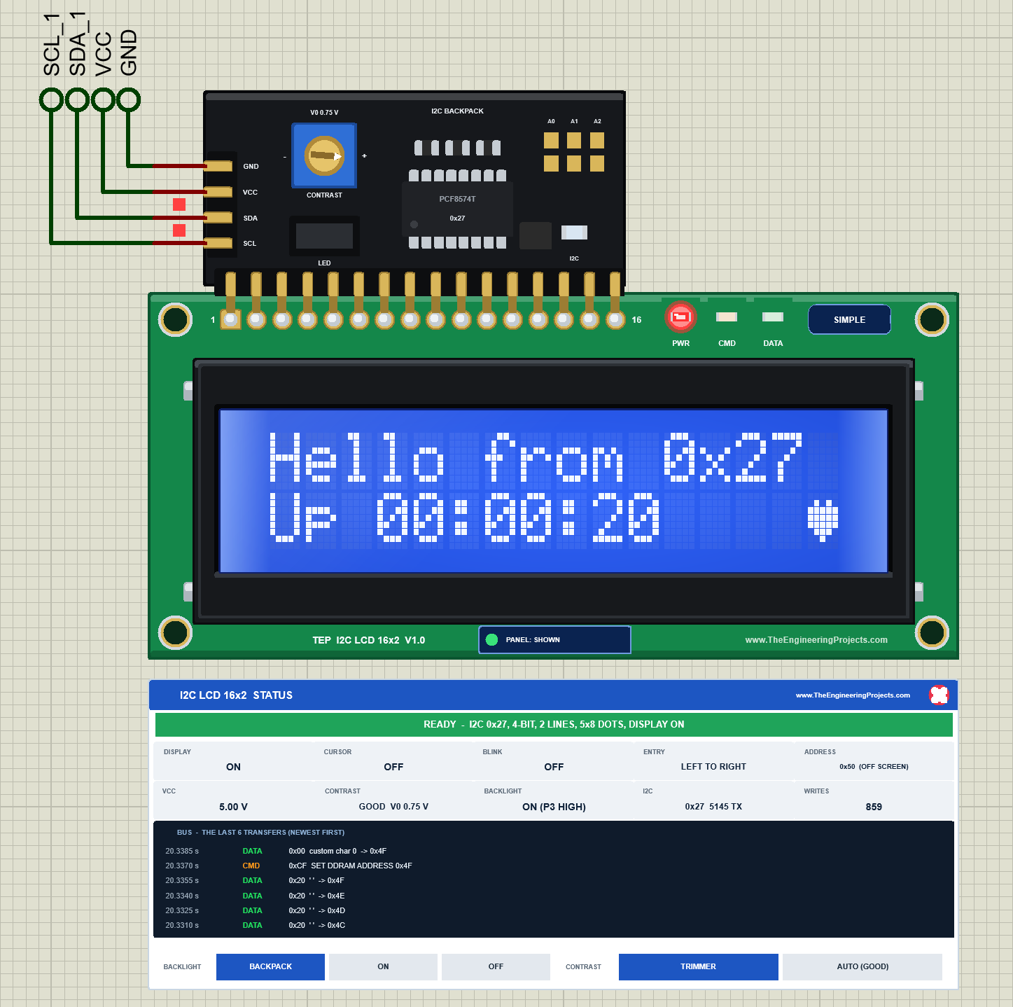
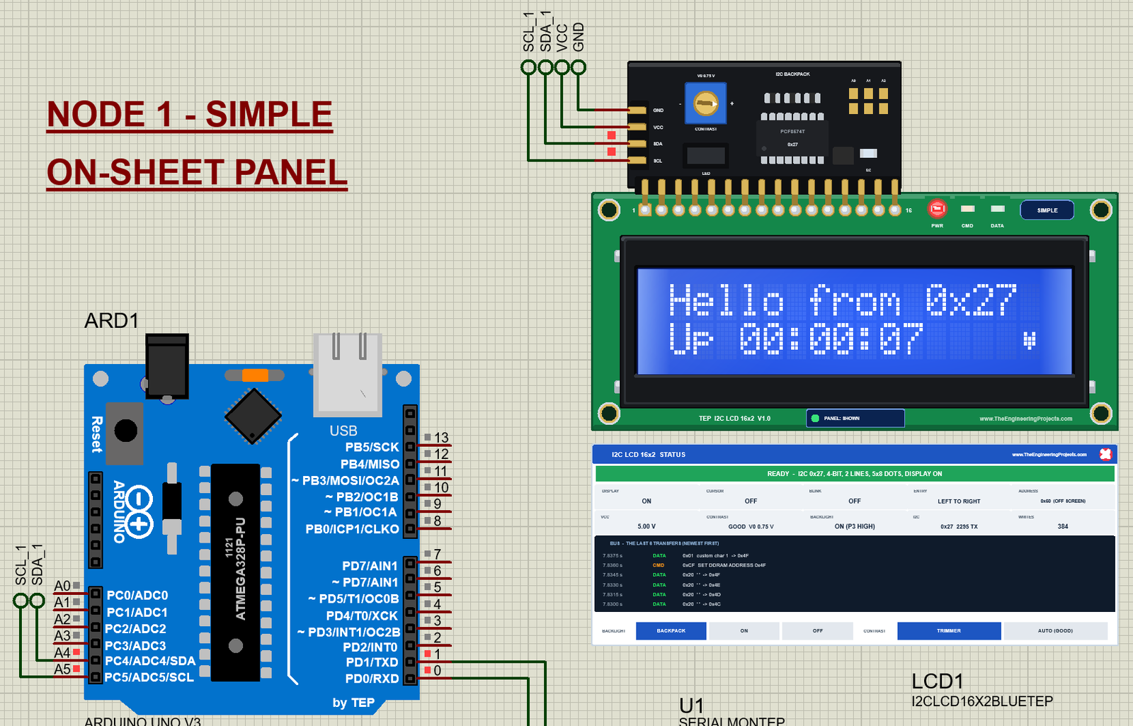
On a real module, the backpack hides behind the LCD. In Proteus we drew it folded up above the LCD, like an exploded view, so you can see and click its parts. The LCD board below it is the one of our LCD 16x2 V3.0: the green PCB in the real 1602 size, the 16 pads (here with the backpack's pins soldered in), the metal frame and the glass with all 32 character cells. The backpack's 4-pin header sits on its left end with the pins pointing left, in the order printed on the real board: GND, VCC, SDA, SCL. Here is LCD1, the blue Simple LCD, in the demo:
Pinout
| Pin | Name | What it does | Demo connection |
|---|---|---|---|
| 1 | GND | Ground | GND (net label) |
| 2 | VCC | Supply, 5 V | VCC (net label, the 5 V rail) |
| 3 | SDA | I2C data (open drain, with the backpack's pull-up) | Arduino A4, through the label SDA_1 |
| 4 | SCL | I2C clock | Arduino A5, through the label SCL_1 |
The Backpack Up Close
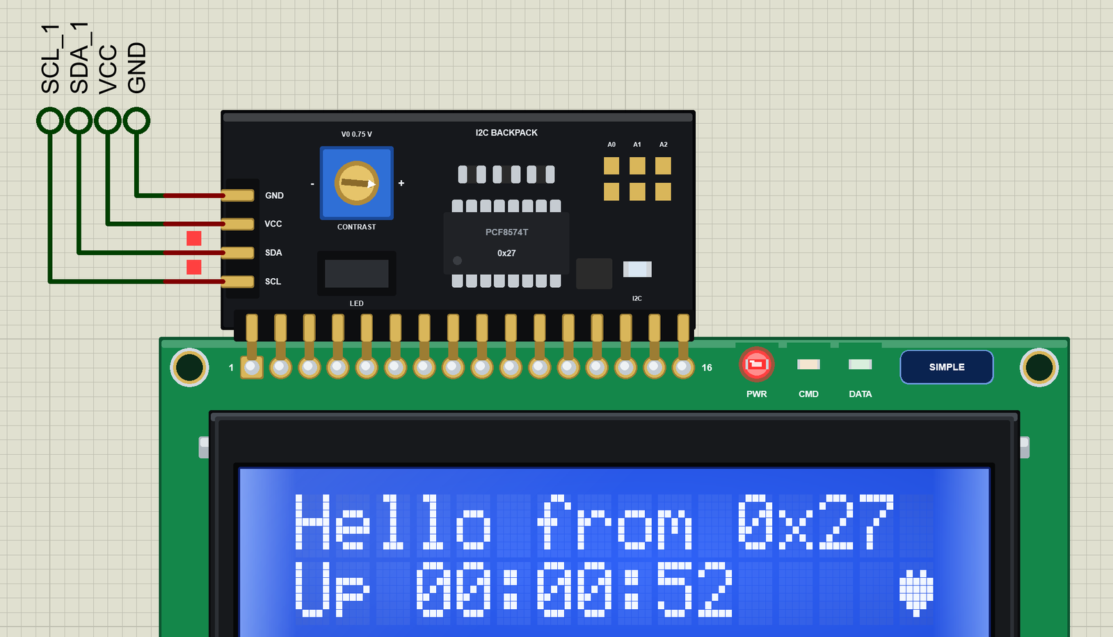
The parts you see are drawn by the model and change while the simulation runs: the trimmer's slot turns and the label above it shows V0, the jumper shows its cap or two bare pins, a bridged pad gets a solder blob, the chip shows its type (PCF8574T or PCF8574AT) and its address, and the small I2C LED flashes blue when the Arduino talks to this address.
LEDs and Indicators
| Indicator | What it shows | On the real module? |
|---|---|---|
| The backlight | The glass glows when P3 is high and the jumper is fitted | Yes |
| PWR LED (red) | Lit while the module has power | TEP addition |
| CMD LED (orange) | Flashes when the LCD takes a command | TEP addition |
| DATA LED (green) | Flashes when the LCD takes a character | TEP addition |
| I2C LED (blue) | Flashes on every I2C transaction to this address | TEP addition |
| Chip marking | PCF8574T or PCF8574AT and the address, live | TEP addition |
| SIMPLE / ADVANCE badge, PANEL / OPEN PANEL | Which device this is, and the panel button | TEP addition |
Component Properties
| Property | Meaning | Default |
|---|---|---|
| PANEL | Simple devices only: the STATUS panel at the start, OPEN or CLOSED | OPEN |
| ADDRESS | 0x20 - 0x27 (a PCF8574T board) or 0x38 - 0x3F (a PCF8574AT board); the pads follow it | 0x27 |
| TRIMMER | The contrast trimmer at the start: V0 in % of VCC (0 = dark blocks, 50 = blank) | 15 |
| LED_JUMPER | FITTED or REMOVED | FITTED |
| BACKLIGHT | BACKPACK (P3 and the jumper), ON or OFF (forced) | BACKPACK |
| CONTRAST | TRIMMER or AUTO (always good) | TRIMMER |
Every run starts from these properties; the clicks on the backpack and the panel's buttons change them for that run only. In the demo, LCD2 has ADDRESS = 0x3F: it is a PCF8574AT board.
Click the Backpack: Trimmer, Jumper and Address Pads
Turning the Contrast Trimmer
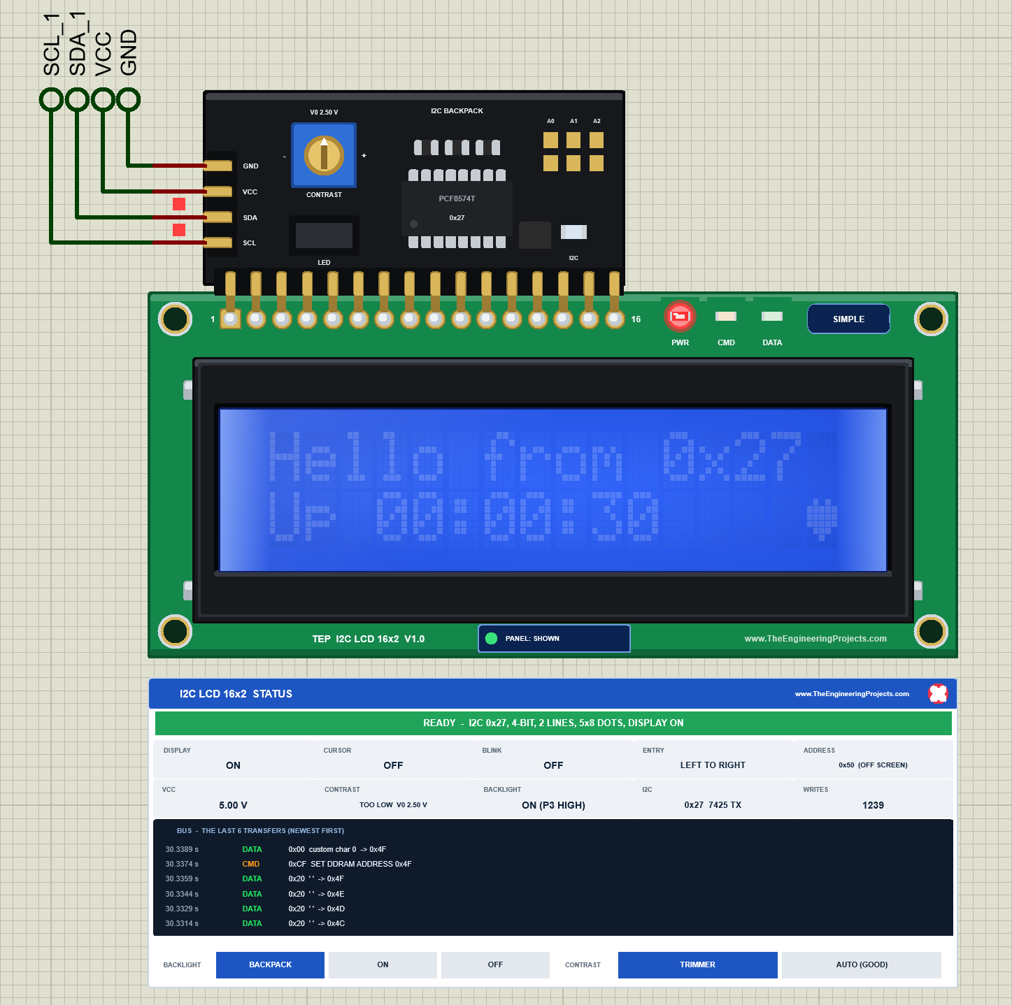
Click the left half of the blue trimmer (the - side) to turn the contrast down, the right half (the + side) to turn it up; each click moves V0 by 5 % of VCC, 0.25 V. At the start V0 is 0.75 V and the contrast is GOOD. Seven clicks on the - side bring V0 to 2.50 V: the characters fade to faint ghosts, and the panel says TOO LOW:
Now ten clicks on the + side: V0 drops to 0 V, the full 5 V is across the crystal, and even the empty dots turn dark. The panel says TOO HIGH:
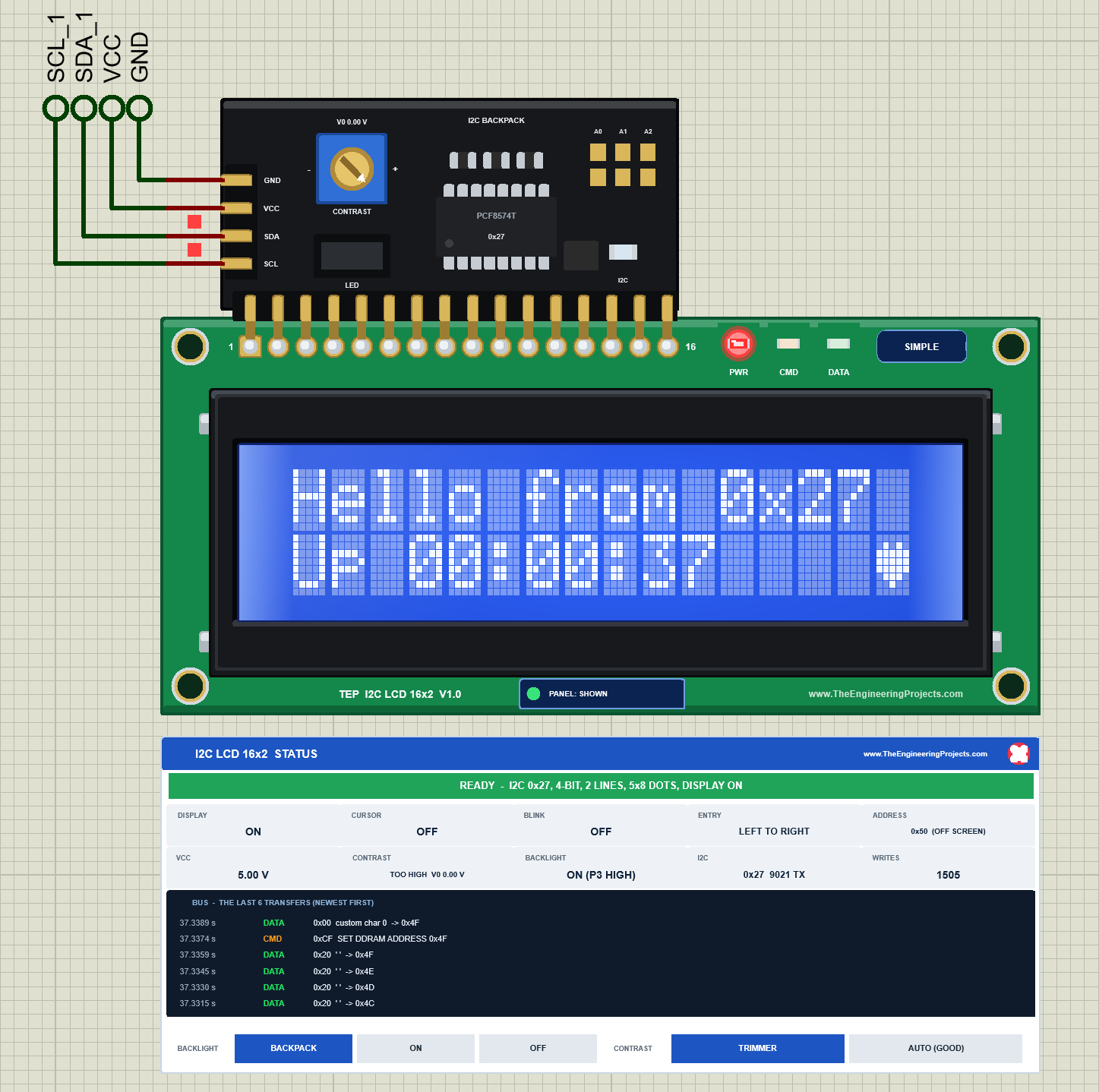
This is the classic "my I2C LCD shows nothing" case. On a real module, turn the trimmer with a small screwdriver until the blocks of the top row just show, then a little back.
Pulling the LED Jumper
Click the LED jumper: its cap comes off, two bare pins show, and the backlight goes out, even though the sketch keeps P3 high. The panel says OFF (NO JUMPER):
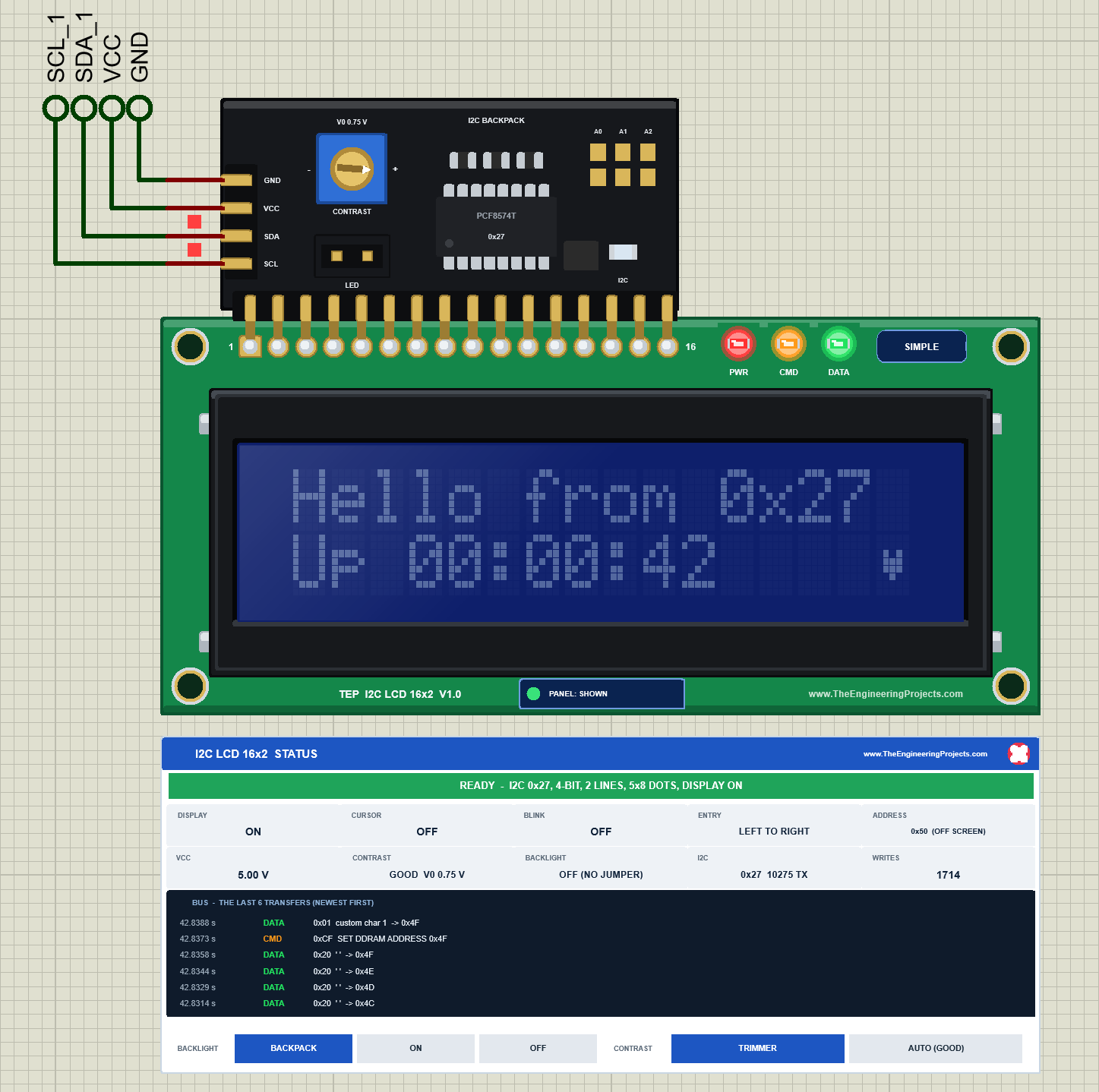
Click it again to fit the cap. The sketch can switch the backlight too: lcd.noBacklight() sets P3 low (the panel then says OFF (P3 LOW)), and lcd.backlight() sets it high again.
Bridging an Address Pad: WRONG ADDRESS
Click pad A0: it gets a solder blob, and the backpack's address becomes 0x26 at once. The sketch still writes to 0x27, so nothing reaches the LCD any more: the clock stops. The banner turns red and says WRONG ADDRESS - THE SKETCH WRITES TO 0x27, THIS BACKPACK IS 0x26, and the I2C readout says 0x26 SKETCH: 0x27:
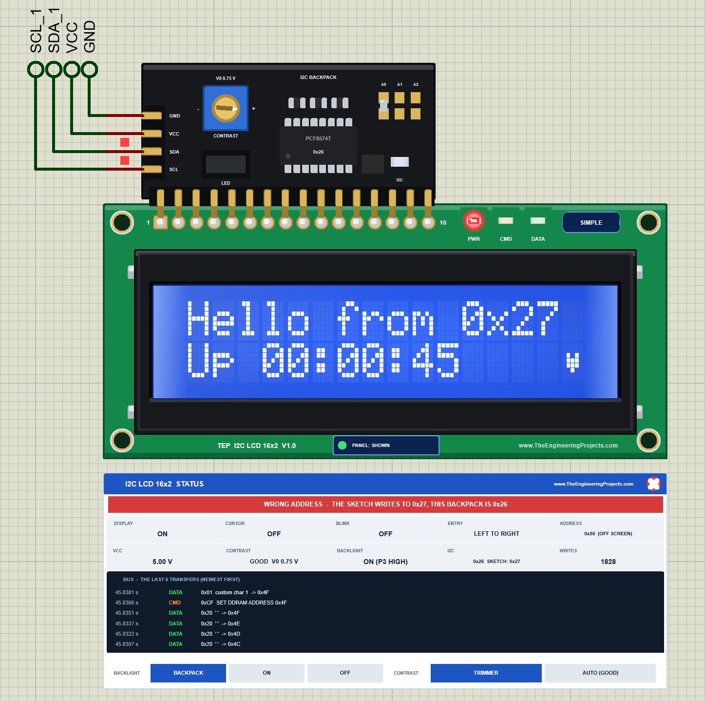
Click the pad again and everything runs on. On a real module, a wrong address looks just like a bad contrast: a blank LCD. In our model you see the reason at once, and the I2C bus tool of the Advance tells you both addresses.
I2C LCD 16x2 Simple: The STATUS Panel
Under the Simple LCD sits the I2C LCD 16x2 STATUS panel (see the pictures above):
| Part | What it shows |
|---|---|
| Banner | READY (with the I2C address, bus, lines and font), WAITING FOR I2C, WRONG ADDRESS, NOT INITIALISED, TOO FAST or NO POWER |
| DISPLAY, CURSOR, BLINK, ENTRY | The display, cursor, blink and entry mode flags |
| ADDRESS | Where the LCD's address counter points (row and column, or OFF SCREEN) |
| VCC, CONTRAST | The supply, and the contrast with V0 (GOOD, WEAK, TOO LOW or TOO HIGH) |
| BACKLIGHT | ON (P3 HIGH), OFF (P3 LOW), OFF (NO JUMPER), or forced |
| I2C | This backpack's address and the transactions so far, or the address the sketch uses instead |
| WRITES | Bytes the LCD took (commands and characters) |
| Bus | The last 6 transfers to the LCD, newest first |
| Buttons | BACKLIGHT (BACKPACK, ON, OFF) and CONTRAST (TRIMMER, AUTO (GOOD)) override the backpack for this run |
The red X in the panel's header closes it, and PANEL on the board opens it again.
I2C LCD 16x2 Advance: The Pop-Up Window
The Advance LCD keeps only the module on the schematic. Here is LCD2, the yellow-green Advance LCD; its chip says PCF8574AT and 0x3F:
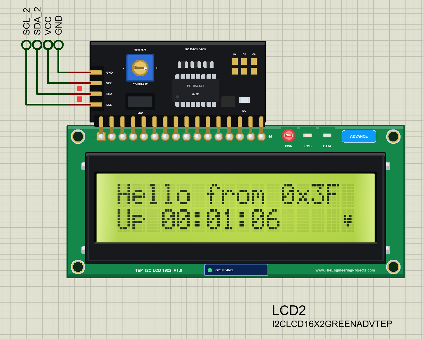
At Run, the "TEP I2C LCD 16x2 Advance" pop-up opens with the look of our TEP Serial Monitor: move it by its header, resize or minimise it, and reopen it with OPEN PANEL. The header has the Display, Bus log and Tests tabs and the theme, Settings and Help icons. Under the header, the BACKLIGHT (Backpack, On, Off) and CONTRAST (Trimmer, Auto) buttons work like the Simple panel's.
The Display Page
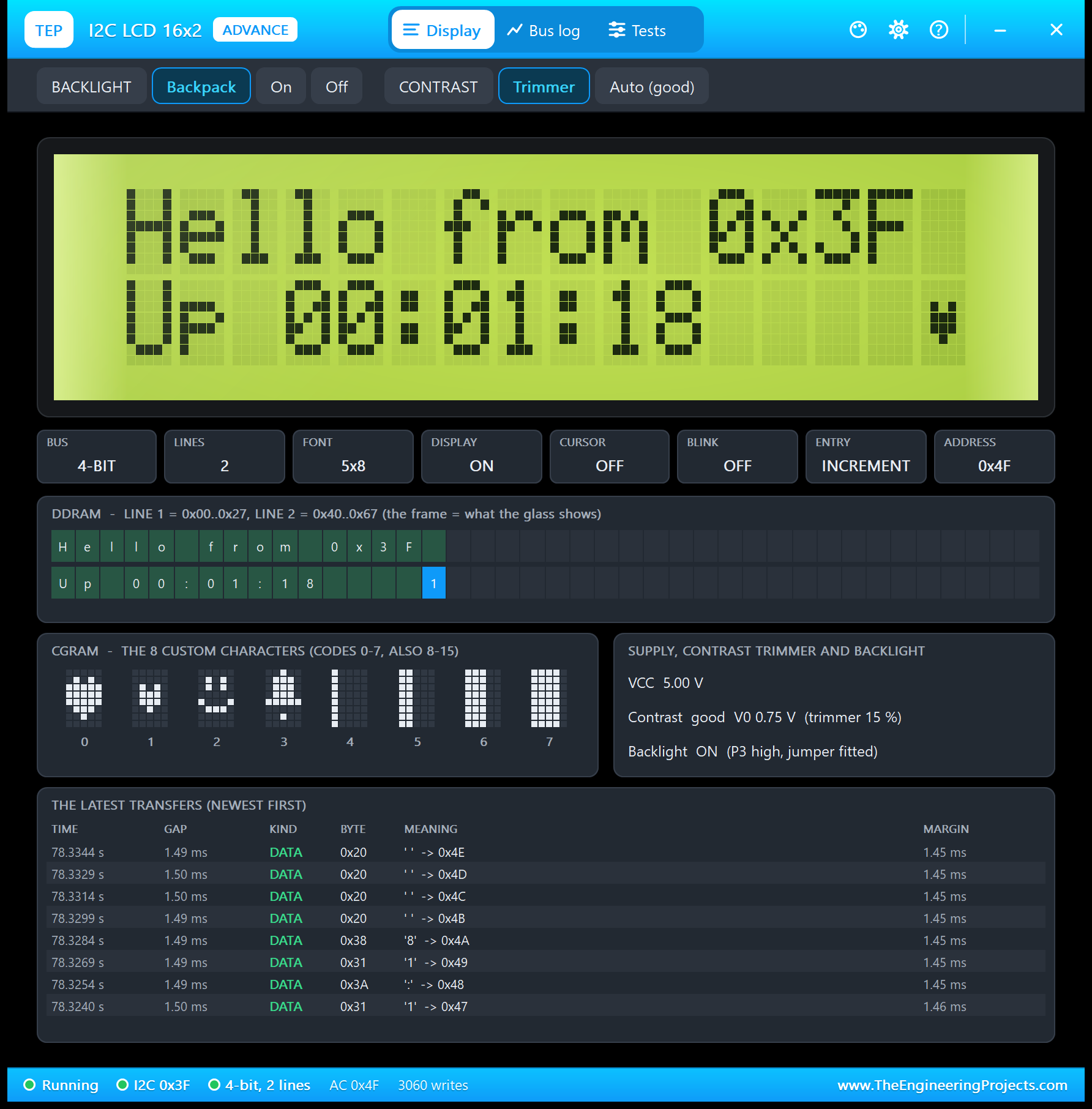
- The glass: a big copy of the LCD, dot by dot.
- Tiles: BUS 4-BIT, LINES 2, FONT 5x8, DISPLAY ON, CURSOR OFF, BLINK OFF, ENTRY INCREMENT and the address counter.
- DDRAM: both lines of 40 bytes; the green frame is what the glass shows.
- CGRAM: the 8 own characters of the demo.
- Supply, contrast trimmer and backlight: VCC, the contrast with V0 and the trimmer setting, and the backlight with P3 and the jumper.
- The latest transfers: the bytes the LCD took, about 1.5 ms apart over I2C.
The Bus Log Page
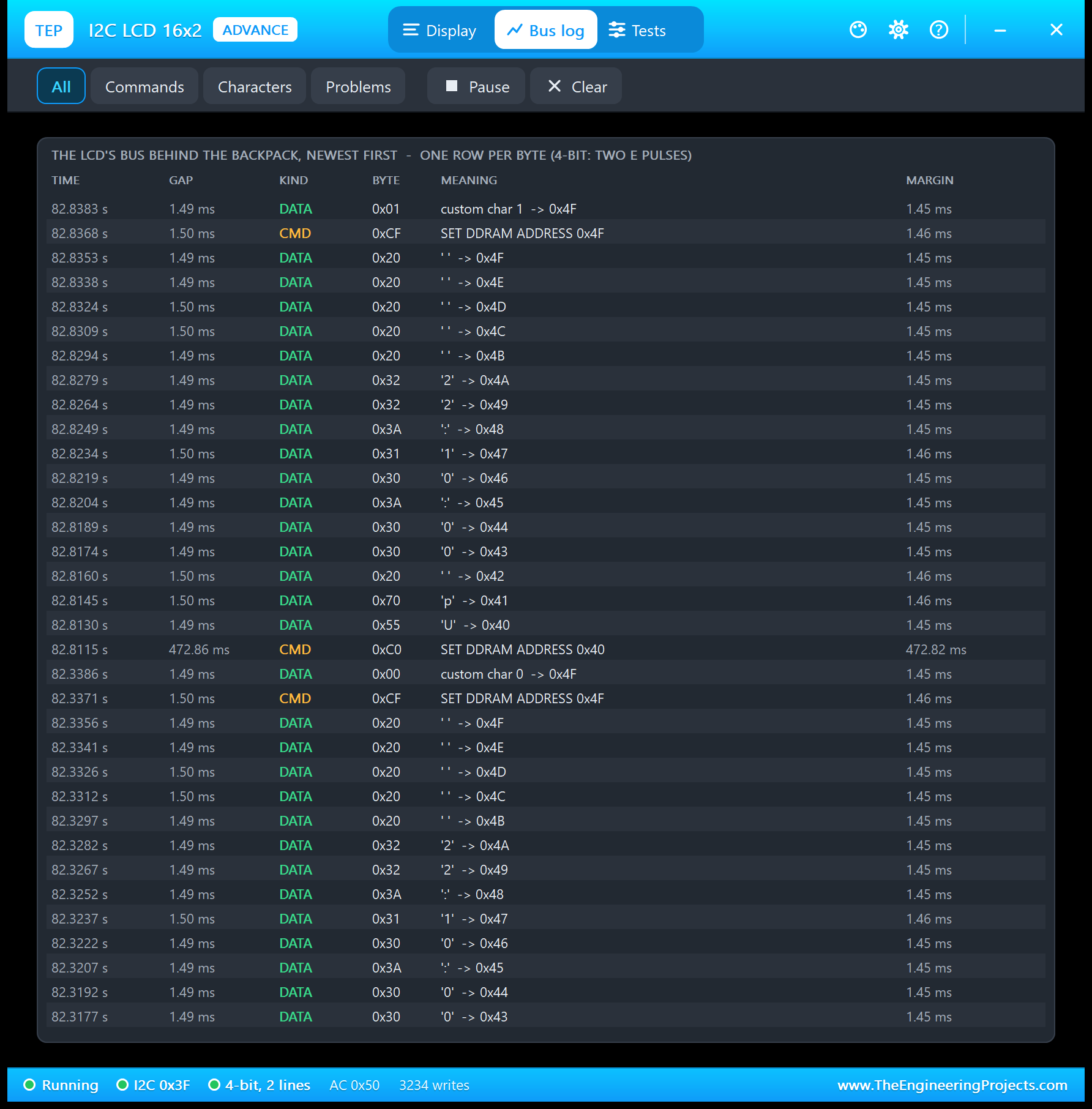
The Bus log shows what the LCD took from the backpack: one row per byte, newest first, with the time, the gap, CMD or DATA, the byte, its meaning and the margin to the busy time. Read the picture from the bottom up: SET DDRAM ADDRESS 0x40 (line 2), then "U", "p", a space, the digits of the clock, and finally the heart. Every byte comes 1.49 ms after the one before: that is the I2C speed. The controller needs only 37 to 41 us, so there is a margin of 1.45 ms.
The Tests Page: Four LCD Test Tools
The tools read the bus as the model sees it during the running simulation. Each has a bold "Good for:" line and a verdict per row: green is fine, amber means check, red means wrong. All the results below come from LCD2 in Proteus 8.5.
1. Init Check: Is the Start-Up Right?
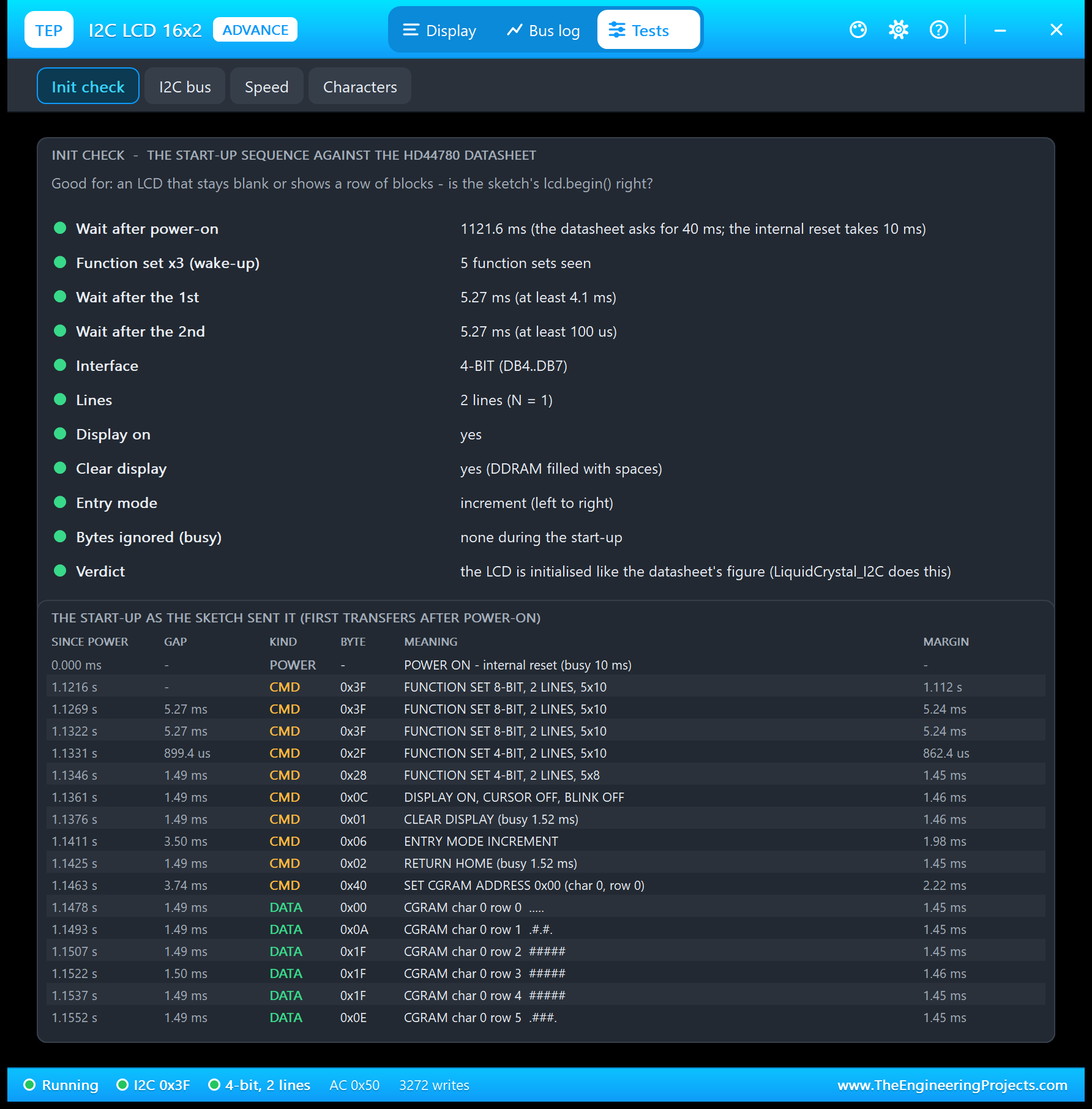
| Check | Result in the picture |
|---|---|
| Wait after power-on | 1121.6 ms (the datasheet asks for 40 ms) |
| Function set x3 (wake-up) | 5 function sets seen |
| Wait after the 1st / 2nd | 5.27 ms / 5.27 ms (at least 4.1 ms / 100 us) |
| Interface, lines | 4-BIT (DB4..DB7), 2 lines (N = 1) |
| Display on, clear, entry mode | Yes, yes, increment (left to right) |
| Bytes ignored (busy) | None during the start-up |
| Verdict | The LCD is initialised like the datasheet's figure |
Why 1121.6 ms? LiquidCrystal_I2C's init() waits 50 ms, writes the port once, and then waits a whole second before it starts the LCD. Add the sketch's address search, and the first command arrives 1.12 s after power-on. In the start-up list, the custom characters appear as rows of dots, for example ".#.#." for 0x0A.
2. I2C Bus: Is the Sketch Talking to This Backpack?
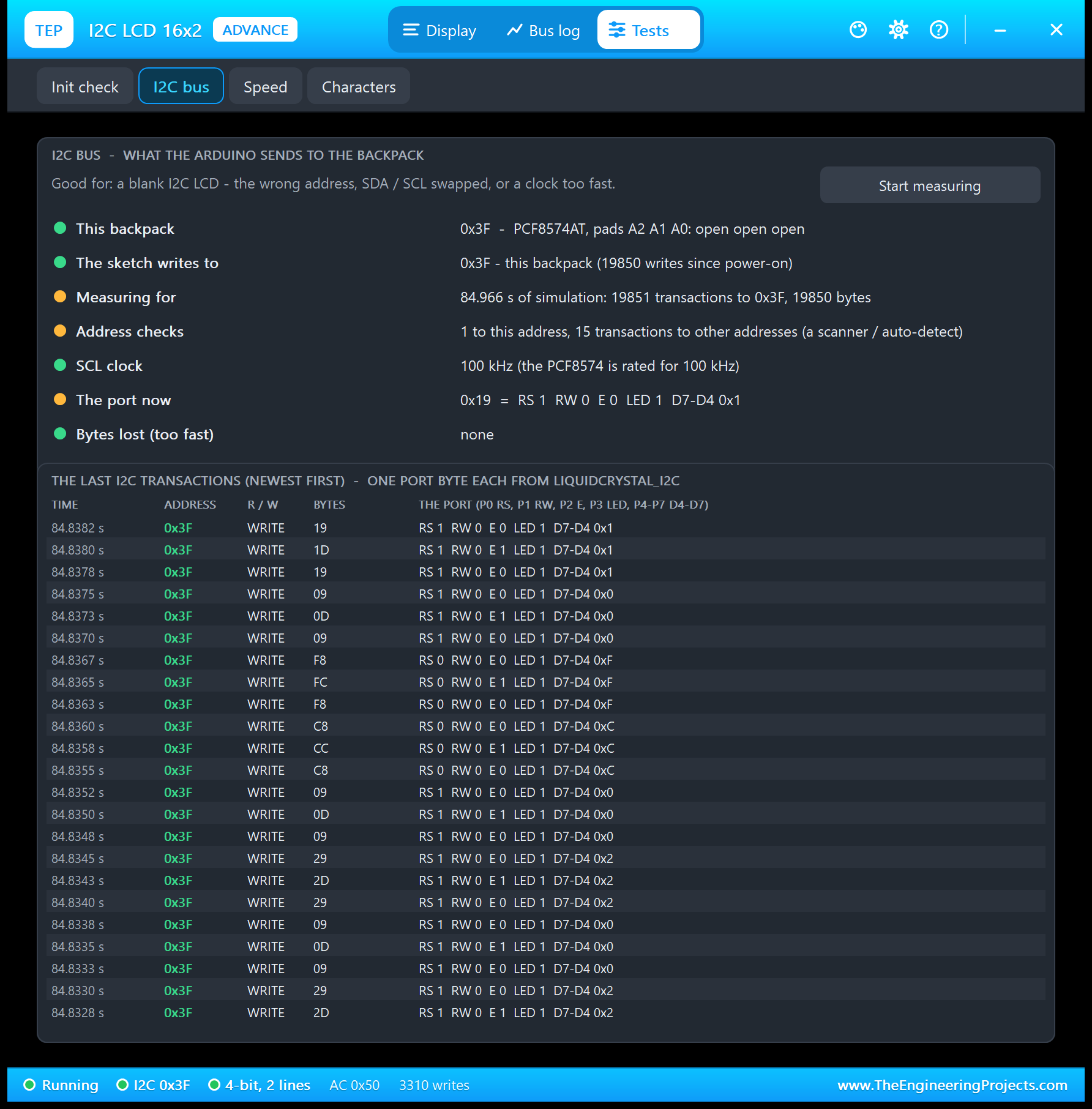
Good for: "a blank I2C LCD - the wrong address, SDA / SCL swapped, or a clock too fast." The tool shows:
| Row | Result in the picture |
|---|---|
| This backpack | 0x3F - PCF8574AT, pads A2 A1 A0: open open open |
| The sketch writes to | 0x3F - this backpack (19850 writes since power-on) |
| Measuring for | 84.966 s of simulation: 19851 transactions to 0x3F, 19850 bytes |
| Address checks | 1 to this address, 15 transactions to other addresses (the sketch's address search) |
| SCL clock | 100 kHz (the PCF8574 is rated for 100 kHz) |
| The port now | 0x19 = RS 1 RW 0 E 0 LED 1 D7-D4 0x1 |
| Bytes lost (too fast) | None |
The 15 address checks are the demo's address search: it tries 0x20 to 0x27 and 0x38 to 0x3E before it finds 0x3F. Below the rows, the last transactions are listed with every port byte decoded: you can watch the E bit go 1, 0, 1, 0 as LiquidCrystal_I2C pulses each nibble.
Now bridge pad A2 of LCD2 (0x3F becomes 0x3B) while the sketch keeps writing to 0x3F. The tool turns red:
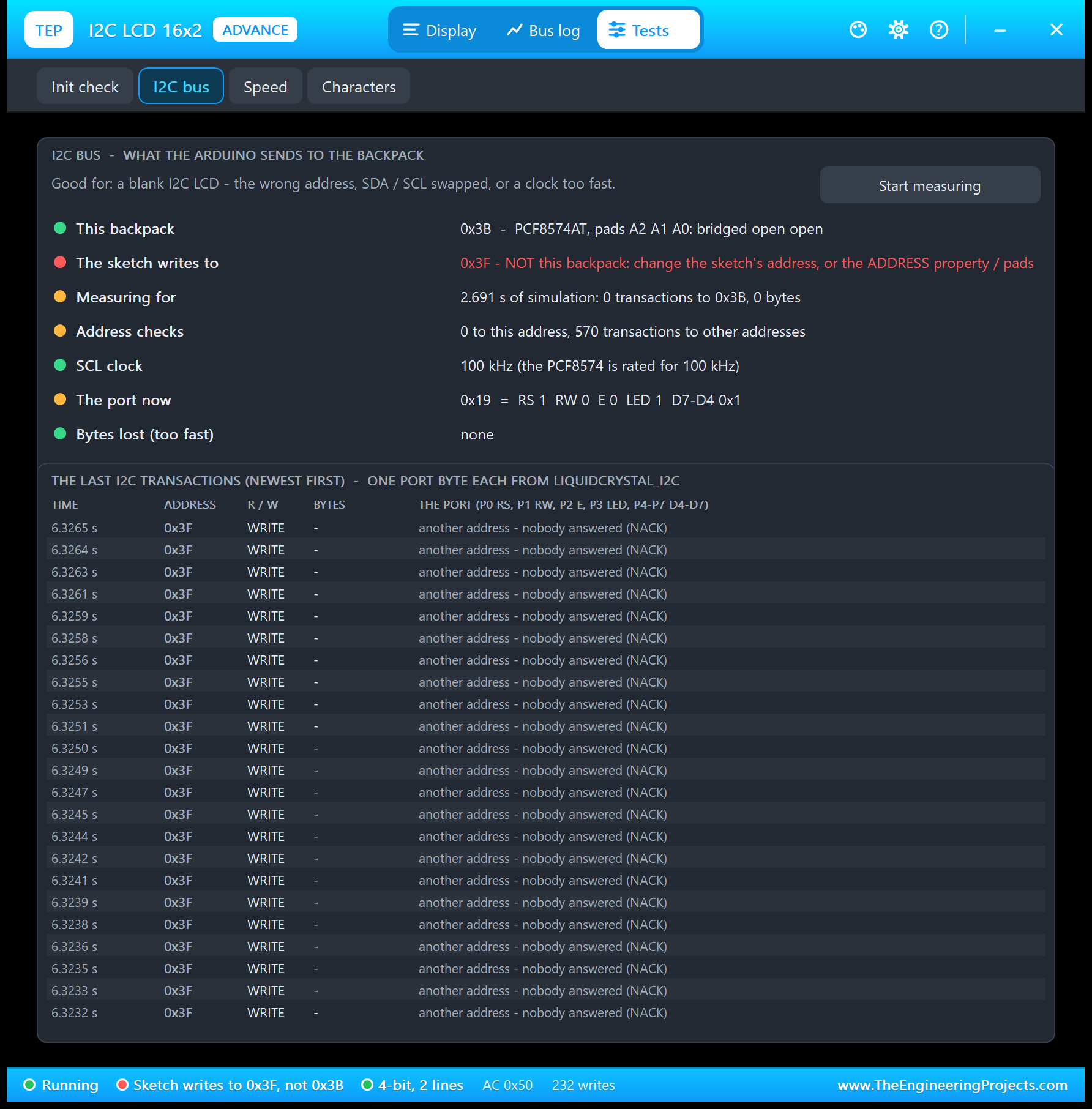
The counters start again at the pad click: in 2.691 s, 0 transactions reached 0x3B and 570 went to 0x3F, where nobody answers any more. Each of them ends with a NACK after the address byte, so the LCD gets nothing. The status bar says it too: "Sketch writes to 0x3F, not 0x3B".
3. Speed: How Fast Is an I2C LCD?
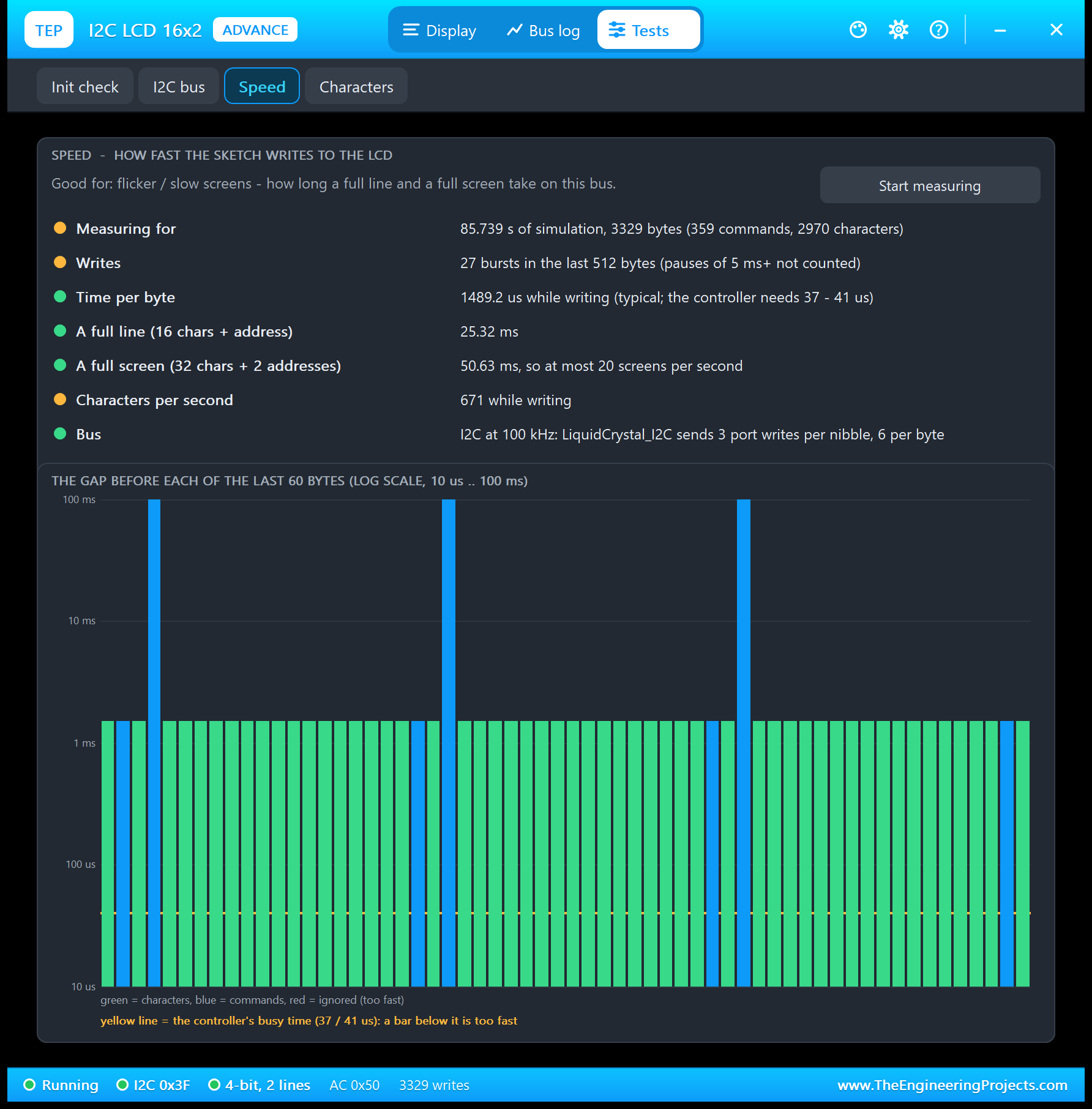
Good for: "flicker / slow screens - how long a full line and a full screen take on this bus." The tool takes the typical gap between two bytes inside a burst of writes:
| Result | Value |
|---|---|
| Time per byte | 1489.2 us (the controller needs only 37 to 41 us) |
| A full line (16 characters + the address) | 25.32 ms |
| A full screen (32 characters + 2 addresses) | 50.63 ms, so at most 20 screens per second |
| Characters per second | 671 while writing |
| Bus | I2C at 100 kHz: LiquidCrystal_I2C sends 3 port writes per nibble, 6 per byte |
Compare it with the same LCD on six pins in our LCD 16x2 V3.0 demo: about 0.3 ms per byte there, 1.5 ms here. For a clock or a menu that is plenty, but a sketch that rewrites the whole screen in a loop will flicker. Update only what changed. The tall blue bars in the chart are the pauses between the clock updates.
4. Characters: Find Any Symbol's Code
Good for: "finding a symbol's code (the degree sign is 0xDF = 223) - click a character." The map shows all 256 codes of the A00 ROM in the datasheet's layout, the characters on the display highlighted. Click one to see its code and the line to print it, for example lcd.write(223);, and, for one of the 8 own characters, its rows as a byte array for createChar(). The LCD 16x2 Library for Proteus V3.0 article shows this tool in a picture.
I2C LCD 16x2 with Arduino in Proteus
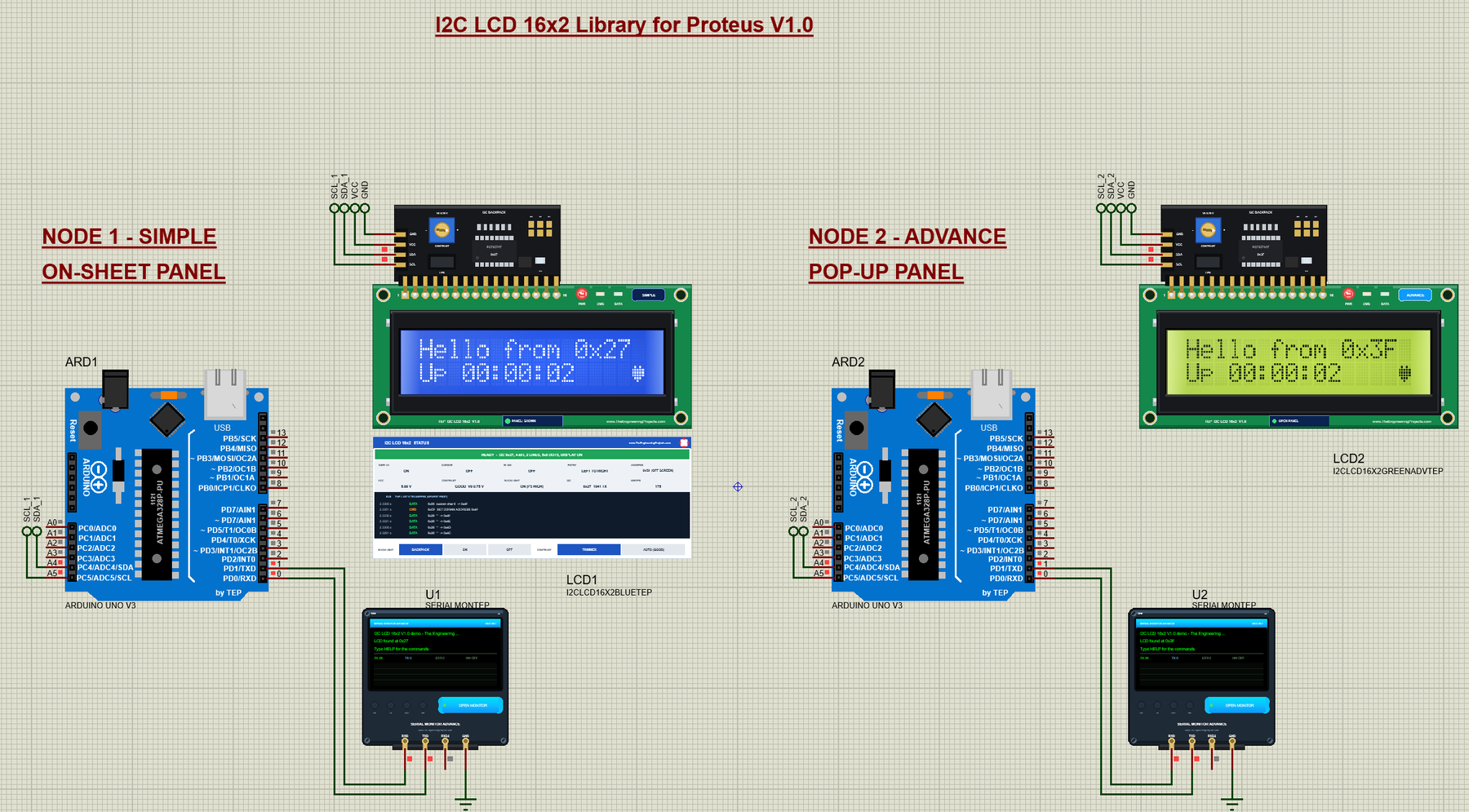
Open I2C-LCD-16x2-ArduinoUnoV3.pdsprj from the Proteus Simulation folder, with I2C_LCD_16x2_Demo.hex and both DLLs beside it. Its two Arduino UNOs from our Arduino Library for Proteus V3.0 run the same HEX file:
- NODE 1 - SIMPLE (on-sheet panel): UNO 1 (ARD1) with LCD1 (blue, Simple, address 0x27) and Serial Monitor U1.
- NODE 2 - ADVANCE (pop-up panel): UNO 2 (ARD2) with LCD2 (yellow-green, Advance, address 0x3F, a PCF8574AT board) and Serial Monitor U2.
Wiring
| Backpack pin | Arduino UNO | Why |
|---|---|---|
| GND | GND | Ground |
| VCC | 5V | Supply |
| SDA | A4 (SDA) | I2C data |
| SCL | A5 (SCL) | I2C clock |
| Serial Monitor RXD / TXD / GND | D1 / D0 / ground | Shows what the Arduino prints, sends what you type |
On an Arduino UNO, SDA is A4 and SCL is A5 (see our Introduction to Arduino UNO). In the demo, every pin goes through a short wire to a net label: in Proteus, terminals with the same name are connected. SDA_1 at the backpack of LCD1 meets SDA_1 at A4 of UNO 1, and node 2 has its own SDA_2 and SCL_2, so the two buses stay apart. VCC and GND are Proteus's power rails.
Why labels and not wires? The backpack's pins and the UNO's A4 / A5 both point left, with SDA above SCL on both. Any pair of wires between them must turn around, and turning around swaps their order, so two direct wires would have to cross. Labels keep the schematic clean.
The Arduino Code
The demo sketch, I2C_LCD_16x2_Demo V1.0, uses the LiquidCrystal_I2C library (version 1.1.2, "LiquidCrystal I2C" by Frank de Brabander in the Library Manager) and Arduino's Wire library. It starts with the LCD object; the address in it is only a starting value:
#include <Wire.h>
#include <LiquidCrystal_I2C.h>

LiquidCrystal_I2C lcd(0x27, 16, 2);    // the address is replaced by the one found
byte lcdAddress = 0;                   // 0 = no LCD answered
The sketch finds the address itself. An I2C address check is an empty write: if a device answers with ACK, Wire.endTransmission() returns 0. The search tries the PCF8574T range first, then the PCF8574AT range:
bool answers(byte a) {                 // an address check: does a device ACK?
  Wire.beginTransmission(a);
  return Wire.endTransmission() == 0;
}

byte findLcd() {                       // the first PCF8574 / PCF8574A address that answers
  const byte first[2] = {0x20, 0x38};
  for (byte b = 0; b < 2; b++)
    for (byte a = first[b]; a < first[b] + 8; a++)
      if (answers(a)) return a;
  return 0;
}
setup() uses what it found: a new LiquidCrystal_I2C object with that address, then lcd.init() and lcd.backlight(). That is why the same HEX file works on both UNOs, at 0x27 and at 0x3F:
void setup() {
  Serial.begin(9600);
  Serial.println(F("I2C LCD 16x2 V1.0 demo - The Engineering Projects"));
  Wire.begin();
  lcdAddress = findLcd();
  if (lcdAddress) {
    lcd = LiquidCrystal_I2C(lcdAddress, 16, 2);
    Serial.print(F("LCD found at ")); printHex(lcdAddress); Serial.println();
  } else Serial.println(F("No I2C LCD found - check SDA (A4), SCL (A5), VCC"));
  lcd.init();                  // the HD44780 start-up over I2C (the library waits ~1 s)
  lcd.backlight();
Then come the 8 own characters (a beating heart in two frames, a smiley, a bell and four bar steps), and the start screen with the address in it. As on any HD44780, createChar() leaves the address counter in CGRAM, so the sketch calls setCursor() before it prints:
byte heartBig[8]   = {0x00, 0x0A, 0x1F, 0x1F, 0x1F, 0x0E, 0x04, 0x00};
byte heartSmall[8] = {0x00, 0x00, 0x0A, 0x0E, 0x0E, 0x04, 0x00, 0x00};
lcd.setCursor(0, 0); // createChar leaves the address in CGRAM
snprintf(text1, sizeof text1, "Hello from 0x%02X", lcdAddress ? lcdAddress : 0x27);
redraw();SCAN lists every device on the bus, from 0x08 to 0x77, with the same address check. It is the classic I2C scanner, built into the demo:
void scan() {                          // SCAN: every device on the bus
  Serial.print(F("I2C devices:"));
  byte n = 0;
  for (byte a = 8; a < 120; a++)
    if (answers(a)) { Serial.print(' '); printHex(a); n++; }
  if (!n) Serial.print(F(" none - check SDA (A4), SCL (A5), VCC"));
  Serial.println();
}
To print a line, the sketch writes the text and pads it with spaces to 16 characters, so a shorter text never leaves old characters behind:
void printLine(byte row, const char* s) {     // the text, padded to 16
  lcd.setCursor(0, row);
  byte n = 0;
  for (; s[n] && n < 16; n++) lcd.print(s[n]);
  for (; n < 16; n++) lcd.print(' ');
}
The clock on line 2 is the up time from millis(), with the heart in the last cell:
void showClock() {
  unsigned long s = millis() / 1000;
  char buf[17];
  snprintf(buf, sizeof buf, "Up %02lu:%02lu:%02lu", s / 3600 % 100, s / 60 % 60, s % 60);
  printLine(1, buf);
  lcd.setCursor(15, 1);
  lcd.write(byte(beat ? HEART_BIG : HEART_SMALL));
}
The bar graph uses 80 steps, 16 cells of 5 columns: a full cell is the ROM's block 0xFF, a part cell one of the four bar characters:
void showBar() {
  int steps = (long)barPercent * 80 / 100;   // 16 cells x 5 columns
  lcd.setCursor(0, 1);
  for (byte c = 0; c < 16; c++) {
    int left = steps - c * 5;
    if (left >= 5) lcd.write(byte(0xFF));
    else if (left >= 1) lcd.write(byte(4 + left - 1));
    else lcd.print(' ');
  }
}
With a backpack, the backlight is not a PWM pin any more but bit P3 of the PCF8574, so the LIGHT command switches it on or off:
  } else if (!strcasecmp(line, "LIGHT")) {
    if (onOff(arg, lightOn)) {
      if (lightOn) lcd.backlight(); else lcd.noBacklight();
      Serial.print(F("OK - backlight ")); Serial.println(lightOn ? F("on") : F("off"));
    }
The loop reads the Serial Monitor, beats the heart twice a second and runs SCROLL one step every 200 ms, without delay():
  unsigned long now = millis();
  if (now - lastTick >= 500) {       // the heart beats twice a second
    lastTick = now;
    beat = !beat;
    if (line2 == SHOW_CLOCK && scrollSteps == 0) { showClock(); parkCursor(); }
  }
To change the sketch, install the library from the Library Manager, export a new HEX file and load it into both UNOs; see How to get the HEX file from Arduino. New to Arduino? Start with our Arduino Tutorial for Beginners.
Serial Monitor Commands
| Command | What it does |
|---|---|
| HELP | The command list |
| STATUS | The LCD's address, line 1, line 2, the backlight, cursor and blink |
| SCAN | Every I2C device on the bus (0x08 - 0x77) |
| TEXT1 <text> | Line 1 (16 characters; a longer text is cut) |
| TEXT2 <text> | Line 2 (the clock stops) |
| CLOCK | Line 2 shows the up time with the beating heart again |
| BAR <0-100> | Line 2 shows a bar graph (80 steps) |
| CHARS | Line 2 shows the 8 own characters |
| LIGHT ON / OFF | The backlight (P3 of the backpack) |
| CURSOR ON / OFF, BLINK ON / OFF | The underline cursor, the blinking block cursor |
| SCROLL | The display slides 16 steps left and back |
| CLEAR | Both lines empty |
How to Run the Demo
- Press Run. Both Serial Monitors (9600 baud) and LCD2's pop-up open; move them aside, as they open over the schematic. After about a second the LCDs show "Hello from 0x27" and "Hello from 0x3F".
- Click the trimmer halves, the LED jumper and an address pad of LCD1, and watch the panel.
- On U1, type LIGHT OFF and LIGHT ON; on U2, SCAN and BAR 75.
- On LCD1's panel, try BACKLIGHT OFF and CONTRAST AUTO (GOOD).
- On LCD2's pop-up, look at the Bus log and run the four tools; bridge a pad of LCD2 and open the I2C bus tool.
I2C LCD 16x2 Proteus Simulation Results
The Serial Monitor in Its Simple Interface
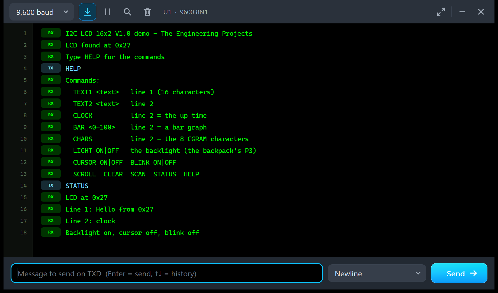
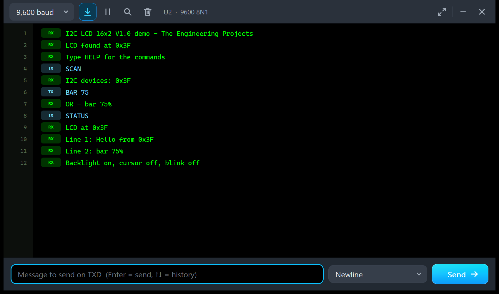
Both monitors in this demo run in the Simple interface of our TEP Serial Monitor, as in every monitor screenshot here: only the log, the send box and one slim toolbar row stay visible.
- Switch to it: right-click the log and choose Simple interface, or press Ctrl+Shift+U.
- Back to the full view: click the corner button, press Esc or Ctrl+Shift+U, or right-click and choose Full interface.
- Your choice is remembered.
Type a command in the send box and press Enter. Every line the demo prints is 80 characters or less. Read all about the monitor in TEP Serial Monitor Advance for Proteus.
U1: HELP and STATUS
I2C LCD 16x2 V1.0 demo - The Engineering Projects
LCD found at 0x27
Type HELP for the commands
HELP
Commands:
  TEXT1 <text>   line 1 (16 characters)
  TEXT2 <text>   line 2
  CLOCK          line 2 = the up time
  BAR <0-100>    line 2 = a bar graph
  CHARS          line 2 = the 8 CGRAM characters
  LIGHT ON|OFF   the backlight (the backpack's P3)
  CURSOR ON|OFF  BLINK ON|OFF
  SCROLL  CLEAR  SCAN  STATUS  HELP
STATUS
LCD at 0x27
Line 1: Hello from 0x27
Line 2: clock
Backlight on, cursor off, blink off
The second line is the address search at work: the sketch found the backpack at 0x27 by itself.
U2: SCAN, BAR and STATUS
I2C LCD 16x2 V1.0 demo - The Engineering Projects
LCD found at 0x3F
Type HELP for the commands
SCAN
I2C devices: 0x3F
BAR 75
OK - bar 75%
STATUS
LCD at 0x3F
Line 1: Hello from 0x3F
Line 2: bar 75%
Backlight on, cursor off, blink off
SCAN finds one device, the backpack at 0x3F: each UNO has its own I2C bus in this demo. Put both LCDs on one bus and SCAN lists both addresses; that is how two I2C LCDs share two wires.
Troubleshooting
- The glass stays dark and the PWR LED is off: no power. Check VCC and GND (the panel says NO POWER with the voltage).
- WAITING FOR I2C: nothing reached this address. Check SDA to A4 and SCL to A5 (swapped lines look the same: nothing works), and that the sketch runs.
- WRONG ADDRESS: the sketch writes to another address. Change the address in the sketch, or the ADDRESS property or the pads; the I2C bus tool shows both addresses.
- A row of blocks on the top line: the LCD was not initialised (lcd.init() or lcd.begin() missing; on the Advance, run the Init check).
- Faint characters or blocks behind them: the contrast. Click the trimmer, or set CONTRAST AUTO (GOOD).
- The backlight stays off: the LED jumper, lcd.backlight() in the sketch, or BACKLIGHT OFF on the panel.
- The part is not simulated, or no monitor window: TEPLCD.DLL or TEPSERIALMON.DLL is missing from MODELS and the project folder; click OPEN MONITOR on a closed monitor.
- The Advance pop-up does not appear: click OPEN PANEL on the board, or turn "Open the panel at Run" back on in Settings.
Things to Know Before Using a Real I2C LCD
The demo sketch uses only Wire, LiquidCrystal_I2C and Serial, so it runs on a real UNO and I2C LCD too. Keep in mind:
- Turn the trimmer first: nine times out of ten, a blank I2C LCD is just the contrast. Turn the blue trimmer on the back until the blocks of the top row show, then a little back.
- Find the address: run an I2C scanner (or the demo's SCAN). A PCF8574T board is 0x27 and a PCF8574AT board 0x3F, unless pads are bridged.
- The LED jumper must be fitted for the backlight; some sketches also forget
lcd.backlight(). - Pull-ups: the backpack has 4.7k pull-ups on SDA and SCL. For long wires or many devices on the bus, check the total.
- 100 kHz: the PCF8574 is rated for Wire's standard 100 kHz; 400 kHz usually works but is outside its datasheet.
- Speed: about 1.5 ms per character, so update only what changed.
Need more room for text? See our Introduction to 20x4 LCD Module.
Limitations of the Simulation
- Not modelled: the PCF8574's interrupt output (not wired on the backpack), I2C timing violations (any clock the AVR makes is accepted; the I2C bus tool shows when it is above 100 kHz), the 5x10 font on the glass, the A02 ROM, the slow response of the liquid crystal and the module's current draw.
- The backpack is drawn above the LCD so you can see its parts; on a real module it sits behind the LCD.
- The model is our own implementation, written from the HD44780 and PCF8574 datasheets. HD44780 is a Hitachi part and PCF8574 an NXP / TI part; this library is not made or endorsed by them or by Labcenter.
- Licences: the demo sketch uses LiquidCrystal_I2C 1.1.2 and Arduino's Wire library. The HEX file contains them and the Arduino AVR core 1.8.6, which includes LGPL-licensed code; its source code is on GitHub.
- Tested in Proteus 8.5 in October 2026 (the demo as shipped, both LCDs, the trimmer, the jumper, the pads, the panel, the pop-up, the four tools and every screenshot here; about 0.32 x real time with the pop-up and both monitors open, the same as our LCD 16x2 V3.0 demo on the same PC) and with automatic PC checks, 0 failed: 65 with the real demo sketch and LiquidCrystal_I2C talking bit by bit to the backpack model, 7,202 on the HD44780 controller, and the demo project read back from disk. Proteus 7 is not supported.
So, that was all about the I2C LCD 16x2 Library for Proteus V1.0. I hope the real I2C address, the clickable trimmer, jumper and pads, and the I2C bus tool make the I2C LCD much easier to understand, so your LCD works the first time you wire a real one. If you use the I2C LCD 16x2 Library for Proteus in a project, please share your feedback in the comments or in our forum, and if you have any questions, ask in the comments and I will help you out. Till the next tutorial, take care and have fun!