Hello friends, I hope you all are doing great. Today, I am going to share the new LCD Library for Proteus V3.0. It brings all our character LCDs together in one library: the LCD 16x2 and the LCD 20x4 on their 16-pin header, and the I2C LCD 16x2 and the I2C LCD 20x4 with the black PCF8574 backpack. You get one LIB file with 16 parts, one model file that runs them all, and a new demo in which a single Arduino UNO drives all four LCDs at the same time.
Each of these LCDs already has its own library and its own article: the LCD 16x2 Library for Proteus V3.0, the LCD 20x4 Library for Proteus V3.0, the I2C LCD 16x2 Library for Proteus V1.0 and the I2C LCD 20x4 Library for Proteus V1.0. This LCD Library for Proteus puts the four of them in one package, so you install one LIB file and one DLL and find every LCD in Pick Devices. Like the four libraries, it is our own HD44780 model, not a new symbol on top of Proteus's built-in LCD: the real timing, the contrast, the backlight, your own characters, the row order of a 20x4 and, on the I2C modules, the PCF8574 backpack with its address pads.
NOTICE: This library is very special to our team. Four LCD modules, one HD44780 model written from the datasheet, an I2C backpack, and now all of it in one library, with a demo that runs four LCDs on one Arduino. It took our team a lot of hard work and many test runs. Your feedback is the fuel that keeps us going, so please tell us what you think in the comments below or in the LCD Library board of our forum. And if our free libraries help you, you can buy us a coffee. So, let's get started with the LCD Library for Proteus V3.0:
What is in LCD Library for Proteus V3.0?
A character LCD shows rows of characters, each a small block of 5x8 dots. On the back of every module sits an HD44780 controller (or a compatible one): your Arduino sends it commands and character codes, and it draws the dots from its character ROM. The library has the four LCD modules you find in most Arduino kits. Two are the plain boards that you wire to the Arduino with six signal wires, and two are the same boards with an I2C backpack soldered on, which need only two:
| Module | Glass | Connection | Arduino library | Its own article |
|---|---|---|---|---|
| LCD 16x2 V3.0 | 2 rows x 16 characters | 16-pin header: RS, E, D4 - D7 (or D0 - D7) | LiquidCrystal | LCD 16x2 Library for Proteus V3.0 |
| LCD 20x4 V3.0 | 4 rows x 20 characters | The same 16-pin header | LiquidCrystal | LCD 20x4 Library for Proteus V3.0 |
| I2C LCD 16x2 V1.0 | 2 rows x 16 characters | PCF8574 backpack: GND, VCC, SDA, SCL | LiquidCrystal_I2C | I2C LCD 16x2 Library for Proteus V1.0 |
| I2C LCD 20x4 V1.0 | 4 rows x 20 characters | The same backpack | LiquidCrystal_I2C | I2C LCD 20x4 Library for Proteus V1.0 |
Every module comes in two colours, blue (white characters on a blue backlight) and yellow-green (dark characters on a yellow-green backlight), and as two devices: Simple, with a live STATUS panel right under the LCD on the schematic, and Advance, with a pop-up window, a bus log and four test tools. That makes the 16 parts:
| Module | Simple | Advance |
|---|---|---|
| LCD 16x2 V3.0 | LCD16X2BLUETEP, LCD16X2GREENTEP | LCD16X2BLUEADVTEP, LCD16X2GREENADVTEP |
| LCD 20x4 V3.0 | LCD20X4BLUETEP, LCD20X4GREENTEP | LCD20X4BLUEADVTEP, LCD20X4GREENADVTEP |
| I2C LCD 16x2 V1.0 | I2CLCD16X2BLUETEP, I2CLCD16X2GREENTEP | I2CLCD16X2BLUEADVTEP, I2CLCD16X2GREENADVTEP |
| I2C LCD 20x4 V1.0 | I2CLCD20X4BLUETEP, I2CLCD20X4GREENTEP | I2CLCD20X4BLUEADVTEP, I2CLCD20X4GREENADVTEP |
These are exactly the parts of the four single-LCD libraries, with the same names, so a design you made with one of them opens with this library too. For the modules themselves, read our Introduction to 16x2 LCD Module and our Introduction to 20x4 LCD Module.
What's New in LCD Library for Proteus V3.0
Our earlier LCD libraries, the New LCD Library for Proteus of 2016 and the LCD Library for Proteus V2.0 of 2023, were symbols on top of Proteus's own LCD model. Version 3.0 is a new start:
- One library, four LCD modules:
TEPLCD.LIBwith all 16 parts, andTEPLCD.DLL, the model that runs them all. - Our own HD44780 model: the real busy times (a byte sent while the controller is busy is lost and reported), DDRAM, CGRAM, the full A00 ROM, cursor and blink, the display shift and the blocks you see before the LCD is initialised.
- The real 20x4 row order: line 1 of the controller on rows 1 and 3, line 2 on rows 2 and 4.
- The I2C backpack: a PCF8574 at 0x20 - 0x27 or a PCF8574A at 0x38 - 0x3F, with the address pads, the contrast trimmer and the LED jumper, which you can click while the simulation runs.
- Real analog pins: the supply, the contrast (V0 with a pot) and the LED backlight (dim it with PWM); open pins get friendly defaults.
- Simple and Advance devices in blue and yellow-green, with PWR, CMD and DATA LEDs on every board.
- A showcase demo: one Arduino UNO drives all four LCDs, two on a shared 4-bit bus and two on one I2C bus, plus the demos of the four single-LCD libraries.
- A compact package: about 1.62 MB, without the C++ source code.
The TEPLCD.DLL in this package is one step newer than the one in the four single-LCD packages: its I2C bus test now lists the bytes for a second device on the same bus as Other devices, which the showcase needs (more on that below). It runs all 16 parts, so keep this one.
Download LCD Library for Proteus
Click the button below to download LCD-Library-for-Proteus-v3.0.zip (about 1.62 MB, without the C++ source code):
LCD Library for Proteus V3.0- README.txt: a detailed guide to the 16 parts, the installation, the showcase wiring and commands, the properties, the test tools and real hardware.
- Proteus Library Files:
TEPLCD.LIB(all 16 parts),TEPSERIALMON.LIBand our Arduino UNO libraryArduinoV3TEP.LIB/ArduinoV3TEP.IDX. - Proteus Model Files:
TEPLCD.DLLandTEPSERIALMON.DLL. - Proteus Simulation: five demo projects with their HEX files: the showcase
LCD-Library-ArduinoUnoV3.pdsprjand the demos of the four single-LCD libraries, plus copies of both DLLs. - Arduino Code: the five sketches. The parallel LCDs use Arduino's LiquidCrystal library, which comes with the Arduino IDE; the I2C LCDs use "LiquidCrystal I2C" by Frank de Brabander from the Library Manager.
No Proteus yet? Read How to Download and Install Proteus 7 and 8. New to libraries? Follow How to Install a New Library in Proteus.
How to Install LCD Library for Proteus
- Close Proteus and extract the whole zip file to a normal folder, for example your Desktop.
- Copy the four files from Proteus Library Files into the LIBRARY folder, usually
C:\Program Files (x86)\Labcenter Electronics\Proteus 8 Professional\LIBRARY(on some PCsC:\ProgramData\Labcenter Electronics\Proteus 8 Professional\LIBRARY; use the folder that already holds Proteus's own .LIB files). - Copy
TEPLCD.DLLandTEPSERIALMON.DLLfrom Proteus Model Files into the MODELS folder. If one of our single-LCD libraries put a TEPLCD.DLL there, replace it with this one. - Installed one of our single-LCD libraries before? Delete its LIB file (
TEPLCD16X2.LIB,TEPLCD20X4.LIB,TEPI2CLCD16X2.LIBorTEPI2CLCD20X4.LIB) from the LIBRARY folder, or Pick Devices lists those parts twice. DeleteTEPLCD.IDXtoo, if there is one. - Start Proteus, press P and search for LCD. The 16 parts are in the category Optoelectronics > Alphanumeric LCDs.
Tip: every demo project needs its .hex file and the two DLLs beside it, so keep the Proteus Simulation folder together. The library was tested in Proteus 8.5; Proteus 7 is not supported.
Parallel or I2C: Which LCD Should You Use?
All four LCDs have the same controller and the same character ROM; they differ in the size of the glass and in how the Arduino reaches the controller. On the 16-pin header, LiquidCrystal drives RS, E and four data lines itself, and each byte goes over as two halves of 4 bits. On the I2C modules, a PCF8574 backpack sits between the Arduino and the header: the Arduino sends every half byte as three I2C writes to the backpack, and the backpack sets the LCD's pins. Here is what that means, measured with the Speed tool of each library's demo:
| LCD 16x2 | LCD 20x4 | I2C LCD 16x2 | I2C LCD 20x4 | |
|---|---|---|---|---|
| Arduino pins | 6 (RS, E, D4 - D7) | 6 (RS, E, D4 - D7) | 2 (SDA A4, SCL A5) | 2 (SDA A4, SCL A5) |
| Time per byte | 0.31 ms | 0.31 ms | 1.49 ms | 1.49 ms |
| A full screen | 10.45 ms | 25.81 ms | 50.63 ms | 125.10 ms |
| Contrast | A 10k pot on V0 | A 10k pot on V0 | The trimmer on the backpack | The trimmer on the backpack |
| Backlight | The A / K pins: dim it with PWM | The A / K pins: dim it with PWM | On or off from the sketch | On or off from the sketch |
| Two on one Arduino | Share RS and D4 - D7, one E pin each | Share RS and D4 - D7, one E pin each | Share SDA and SCL, one address each | Share SDA and SCL, one address each |
So pick a parallel LCD when you have six free pins and want fast updates or a dimmable backlight, and an I2C LCD when the pins are short, for example with sensors, a keypad and an LCD on one UNO, and a few screens per second are enough. And as the last row says, you can have several of either kind on one Arduino. That is what the new demo shows.
The Showcase: One Arduino UNO Drives All Four LCDs
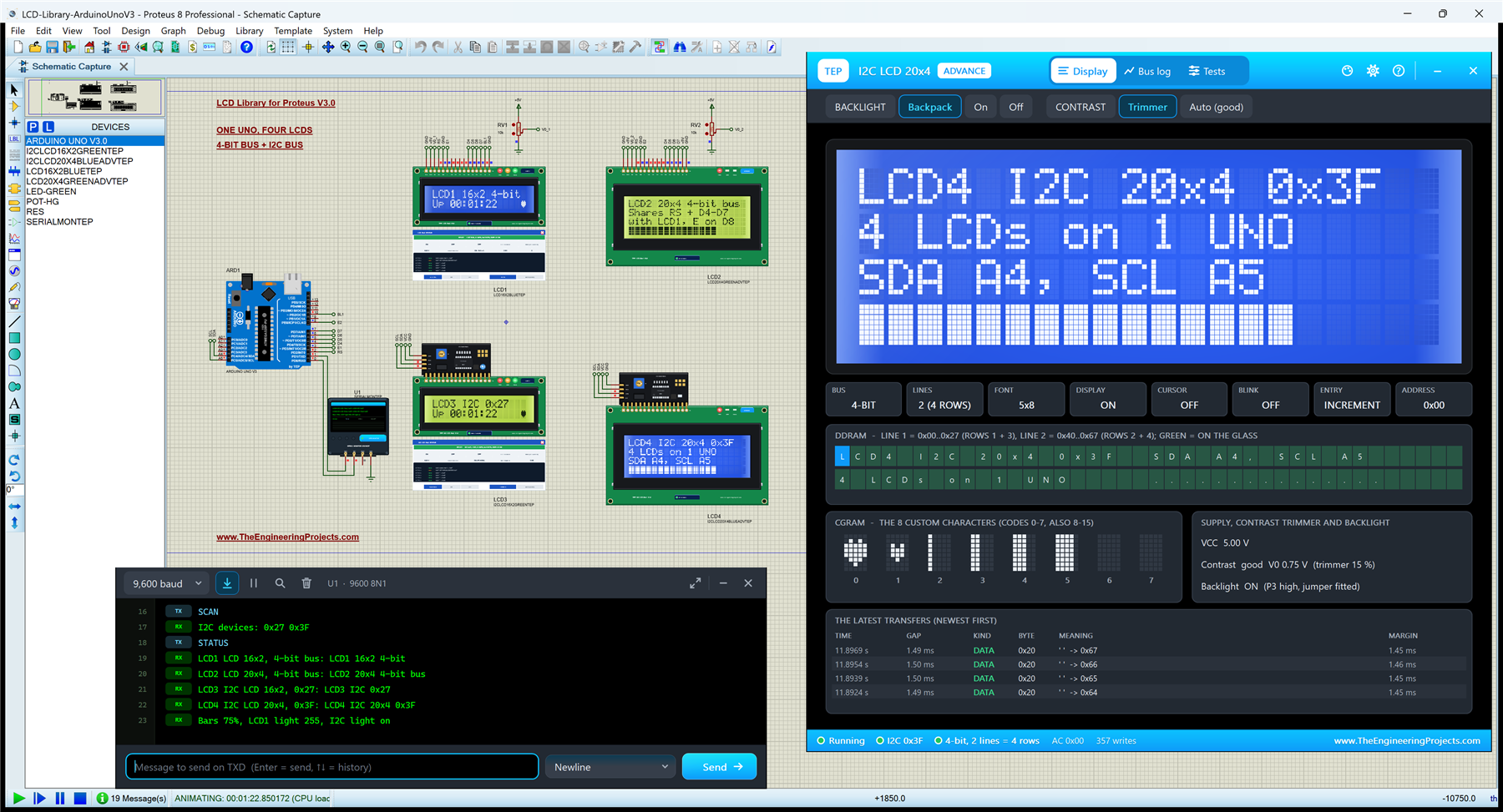
Open LCD-Library-ArduinoUnoV3.pdsprj from the Proteus Simulation folder, with LCD_Library_Demo.hex and both DLLs beside it. One Arduino UNO from our Arduino Library for Proteus V3.0 runs all four LCDs (see our Introduction to Arduino UNO for its pins):
- LCD1: LCD 16x2, blue, Simple, on the 4-bit bus, with its contrast pot RV1 and the backlight on D10 (PWM).
- LCD2: LCD 20x4, yellow-green, Advance, on the same 4-bit bus with its own E pin, D8, its pot RV2 and the backlight on +5V.
- LCD3: I2C LCD 16x2, yellow-green, Simple, at address 0x27 (a PCF8574T backpack).
- LCD4: I2C LCD 20x4, blue, Advance, at address 0x3F (a PCF8574AT backpack), on the same SDA and SCL.
- U1: our TEP Serial Monitor on D0 / D1, for the commands.

At the start, every LCD names itself on its first row: "LCD1 16x2 4-bit", "LCD2 20x4 4-bit bus", "LCD3 I2C 0x27" and "LCD4 I2C 20x4 0x3F". The two 16x2s show the up time with a beating heart. The two 20x4s show two lines about their bus and a bar on row 4 that fills once a minute. The four screens appear together about two seconds after Run; the reason is in the code below.
Two LCDs on One 4-Bit Bus
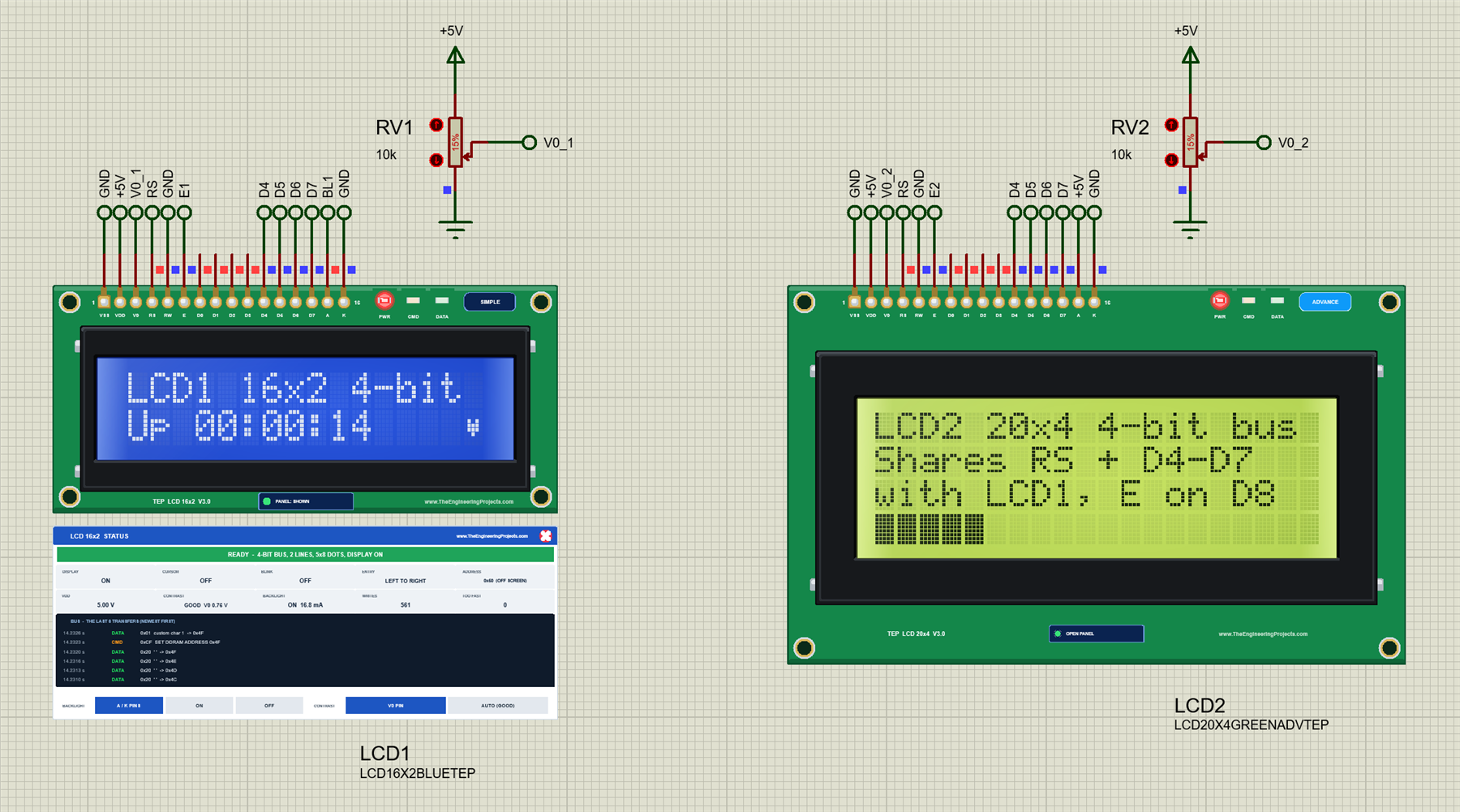
An HD44780 reads RS and the data lines only when its E pin pulses. So two parallel LCDs can share RS and D4 to D7, as long as each one has its own E pin. In the sketch that is simply two LiquidCrystal objects with the same pins, except the second one, E:
LiquidCrystal lcd1(2, 3, 4, 5, 6, 7);   // RS, E, D4, D5, D6, D7
LiquidCrystal lcd2(2, 8, 4, 5, 6, 7);   // RS and D4..D7 shared with LCD1, own E
When the sketch prints on LCD1, LiquidCrystal pulses D3: LCD1 takes the byte, and LCD2 ignores it, although it sees the same levels on RS and D4 to D7. You can watch this in LCD2's Bus log, which lists every byte LCD2 took:
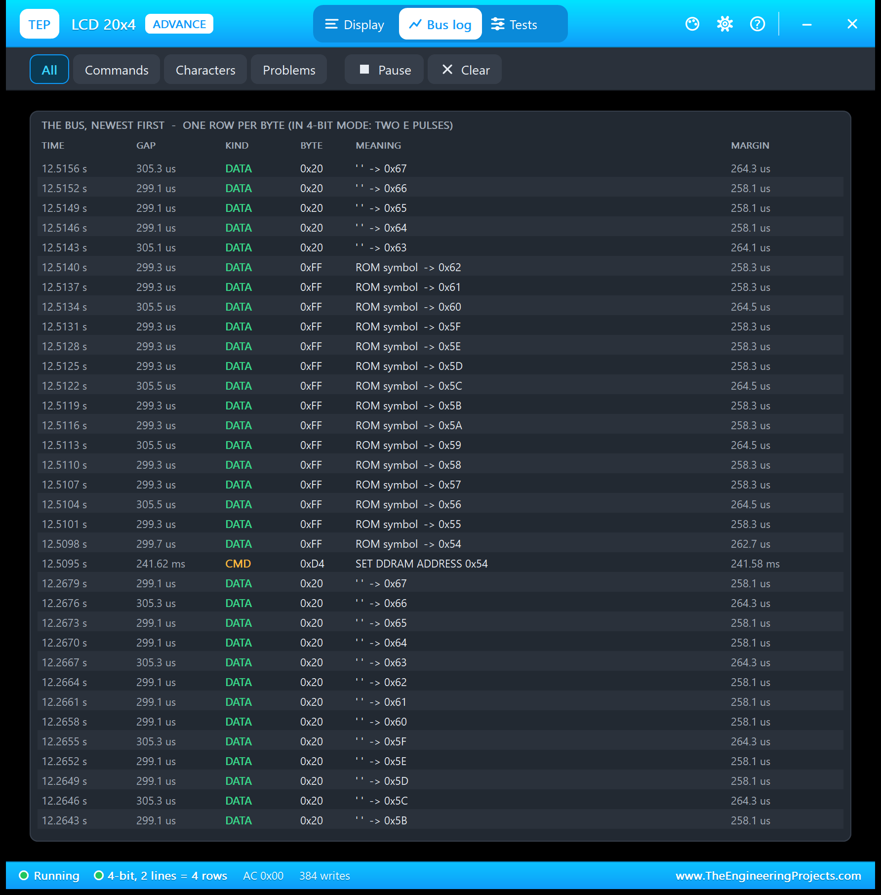
LCD1's clock rewrites its second row twice a second over the very same RS and D4 to D7 wires, but not one of those bytes is in the log: LCD2's E pin, D8, stayed low, so LCD2 never took them. If two LCDs of yours show the same text, check this first: they share an E pin.
Two I2C LCDs on One Bus
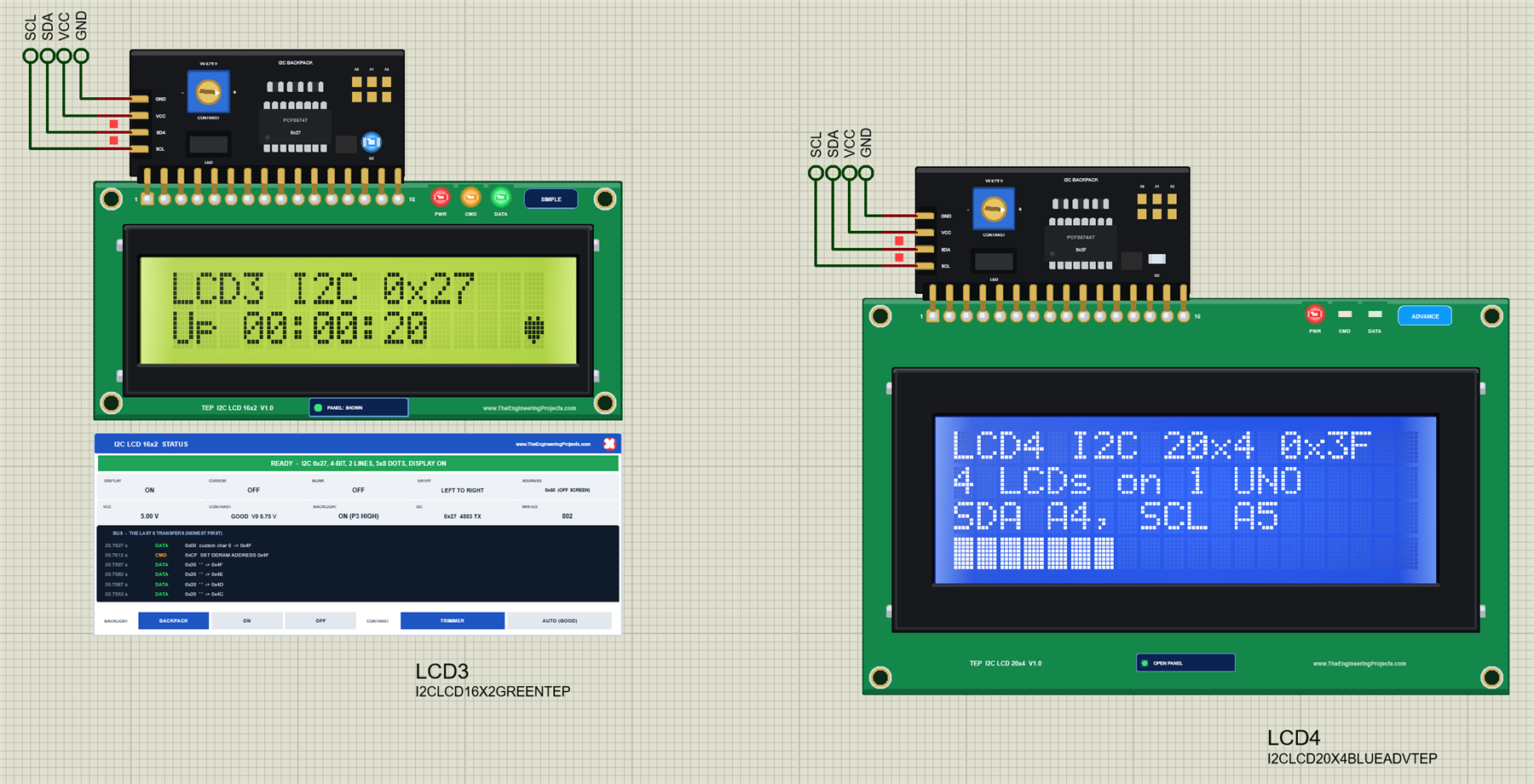
I2C works the other way round: every device on the bus has an address, and the Arduino starts every transfer with it. A backpack answers and takes the bytes only for its own address. The two common backpack chips have different ranges: the PCF8574T from 0x20 to 0x27 and the PCF8574AT from 0x38 to 0x3F, and three solder pads, A0 to A2, pick the address inside the range. In the showcase, LCD3 has a PCF8574T at 0x27 and LCD4 a PCF8574AT at 0x3F, both with the pads open, so they share SDA and SCL without a conflict:
LiquidCrystal_I2C lcd3(0x27, 16, 2);    // the backpack's address and the LCD size
LiquidCrystal_I2C lcd4(0x3F, 20, 4);
LCD4 is an Advance LCD, so it shows how this looks from the backpack's side. Open its pop-up, go to Tests and click I2C bus:
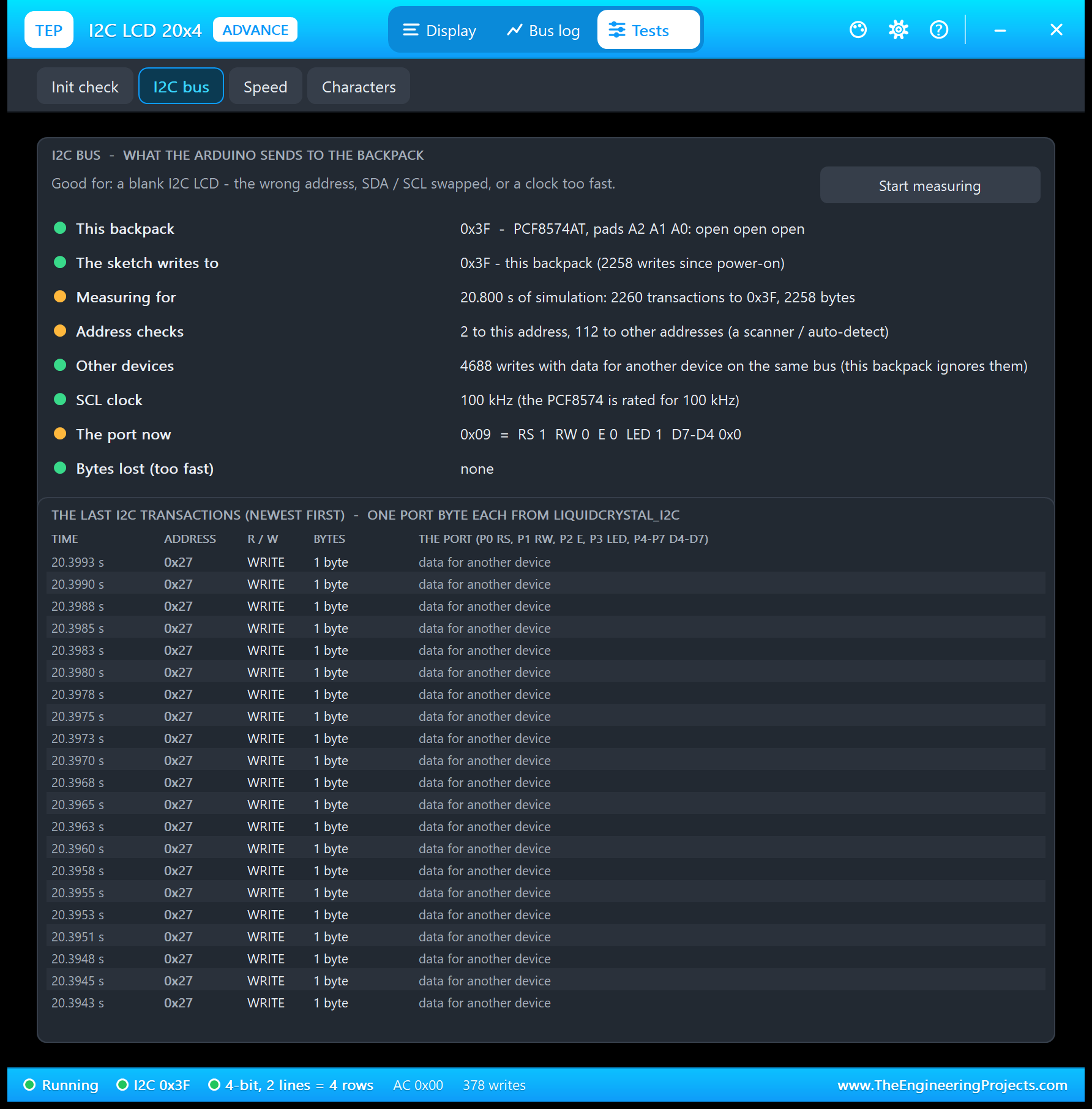
The Address checks are the empty transfers a sketch uses to find a device: one for each backpack at the start, and one for every address from 0x08 to 0x77 in the SCAN command. Two of them reached LCD4's 0x3F, 112 went to other addresses. The Other devices row counts the writes that carried data for another address, here LCD3's 0x27: LCD4's backpack sees them all on the bus and ignores them, just like a real PCF8574. This row is new in this library's DLL; the single-LCD demos have one LCD per bus, so it never shows there.
Wiring
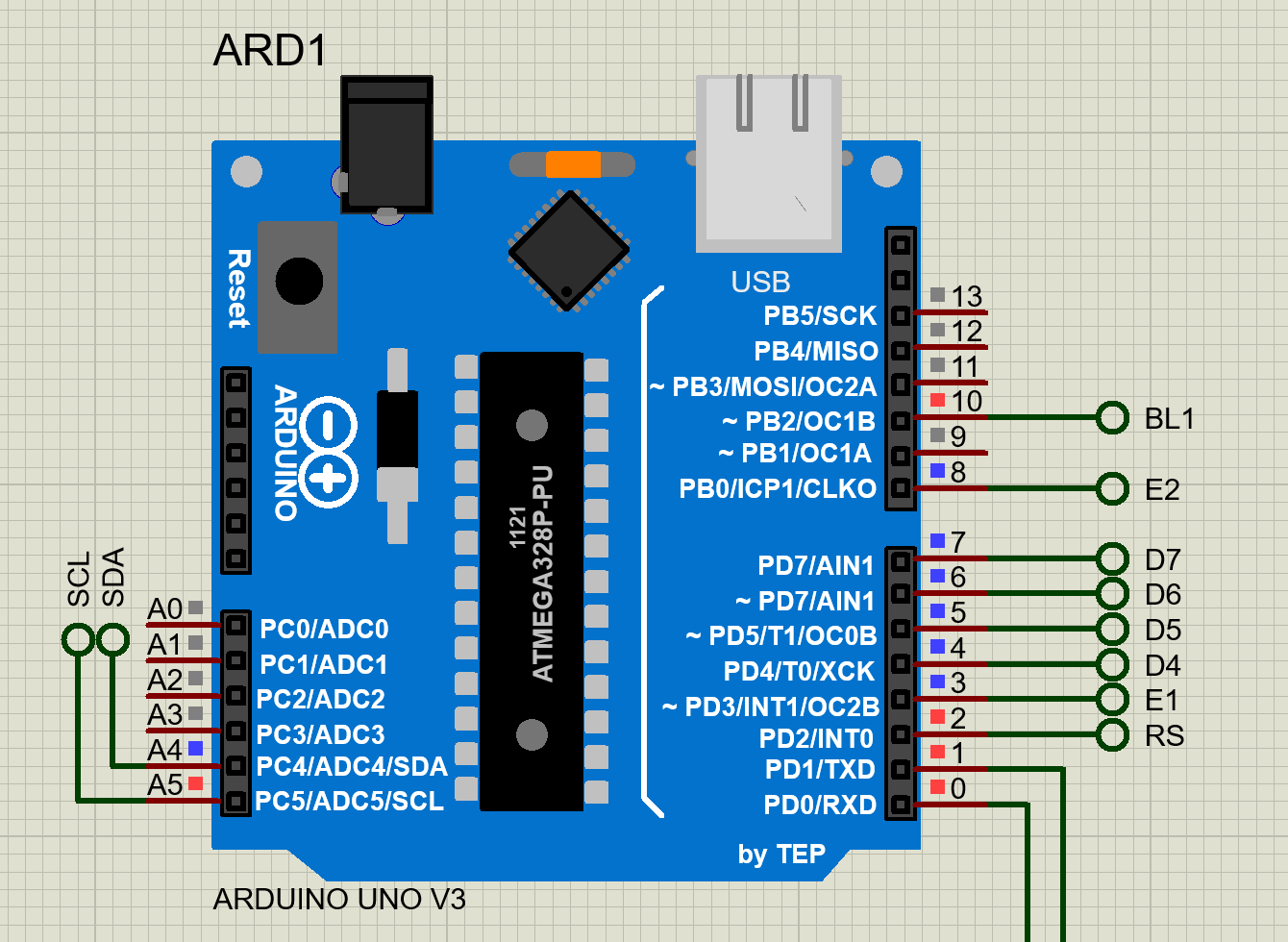
| LCD | Signals | Power, contrast, backlight |
|---|---|---|
| LCD1 LCD 16x2 | RS D2, E D3, D4 - D7 to D4 - D7 | VDD +5V; RW, VSS, K to GND; V0 the wiper of RV1 (10k); A to D10 (PWM) |
| LCD2 LCD 20x4 | RS D2, E D8, D4 - D7 to D4 - D7 (the same wires as LCD1) | VDD +5V; RW, VSS, K to GND; V0 the wiper of RV2; A to +5V |
| LCD3 I2C LCD 16x2 | SDA A4, SCL A5 | VCC +5V, GND; address 0x27 |
| LCD4 I2C LCD 20x4 | SDA A4, SCL A5 (the same bus) | VCC +5V, GND; address 0x3F |
| Serial Monitor U1 | RXD from D1, TXD to D0 | GND (RXD2 is not needed) |
Every connection is a short wire to a terminal with a net label: in Proteus, terminals with the same name are connected. So the RS label on the UNO's D2 meets the RS pins of LCD1 and LCD2, and SDA and SCL reach both backpacks, without a single crossing wire. The labels are RS, E1, E2, D4 to D7, BL1, V0_1, V0_2, SDA, SCL, +5V, VCC and GND.
The Arduino Code
The showcase sketch, LCD_Library_Demo V3.0, uses Arduino's LiquidCrystal library (version 1.0.7, it comes with the Arduino IDE) for LCD1 and LCD2, the LiquidCrystal_I2C library (version 1.1.2) for LCD3 and LCD4, and the Wire library for the I2C bus:
#include <Wire.h>
#include <LiquidCrystal.h>
#include <LiquidCrystal_I2C.h>
In setup(), each LCD starts with its own call: begin() with the size for the parallel ones, init() for the I2C ones, which got their size in the constructor. Before that, the sketch checks that both backpacks answer:
  lcd1.begin(16, 2);
  lcd2.begin(20, 4);
  Wire.begin();
  found3 = answers(0x27);
  found4 = answers(0x3F);
  lcd3.init(); lcd3.backlight();         // LiquidCrystal_I2C waits ~1 s in init()
  lcd4.init(); lcd4.backlight();
LiquidCrystal_I2C switches the backpack's backlight off and waits one second in each init(), and the sketch prints the start screens only when all four LCDs are ready, so they appear together after about two seconds. The address check is a transfer without data: the device with this address answers with an ACK, and endTransmission() returns 0:
bool answers(byte a) {                  // an address check: does a device ACK?
  Wire.beginTransmission(a);
  return Wire.endTransmission() == 0;
}
The SCAN command calls it for every address from 0x08 to 0x77 and prints the ones that answer, a handy check for any I2C project:
  for (byte a = 8; a < 120; a++)
    if (answers(a)) { Serial.print(' '); printHex(a); k++; }
Both LCD libraries are built on Arduino's Print class, so one small function returns "LCD n" as a Print object, and the rest of the sketch prints on any of the four LCDs the same way. Only setCursor() needs its own little switch:
Print& out(byte n) {
  if (n == 0) return lcd1;
  if (n == 1) return lcd2;
  if (n == 2) return lcd3;
  return lcd4;
}
printLine() moves to the start of a row and pads the text with spaces to the width of that LCD, 16 or 20, so a shorter text never leaves old characters behind:
void printLine(byte n, byte row, const char* s) {   // the text, padded to the width
  at(n, 0, row);
  byte k = 0;
  for (; s[k] && k < cols(n); k++) out(n).print(s[k]);
  for (; k < cols(n); k++) out(n).print(' ');
}
All four LCDs get the same six own characters: two hearts for the beating heart and four bar steps. On the 20x4s, row 4 is a bar of 20 cells with 5 columns each, so 100 steps; a full cell is the ROM's block 0xFF and a part cell one of the bar characters, codes 2 to 5. If the bar has not changed, nothing is sent at all:
void showBar(byte n, int steps, int& shown) {   // row 4 of a 20x4: 0..100 steps
  if (steps == shown) return;
  shown = steps;
  at(n, 0, 3);
  for (byte c = 0; c < 20; c++) {
    int left = steps - c * 5;
    if (left >= 5) out(n).write(byte(0xFF));
    else if (left >= 1) out(n).write(byte(2 + left - 1));
    else out(n).print(' ');
  }
}
The backlights work differently on the two kinds of LCD. LCD1's backlight anode is on D10, a PWM pin, so the LIGHT command dims it with analogWrite(). A backpack switches its backlight with its port pin P3, which LiquidCrystal_I2C sets with backlight() and noBacklight(): on or off, nothing in between:
if (i2cLight) { lcd3.backlight(); lcd4.backlight(); } else { lcd3.noBacklight(); lcd4.noBacklight(); }The loop reads the Serial Monitor and, twice a second, beats the hearts and updates the two clocks and the bars. To change the sketch, export a new HEX file and load it into the UNO; see How to get the HEX file from Arduino. New to Arduino? Start with our Arduino Tutorial for Beginners.
Serial Monitor Commands
| Command | What it does |
|---|---|
| HELP | The command list |
| STATUS | The four LCDs (type, found or NOT FOUND, row 1), the bars and the backlights |
| SCAN | Every I2C device on the bus (0x08 - 0x77) |
| TEXT1 <text> ... TEXT4 <text> | Row 1 of LCD1 ... LCD4 (16 or 20 characters; a longer text is cut) |
| ALL <text> | Row 1 of all four LCDs |
| BAR <0-100> | A fixed bar on row 4 of both 20x4s (100 steps) |
| MINUTE | The bars fill once a minute again |
| LIGHT <0-255> | LCD1's backlight PWM on D10 |
| I2CLIGHT ON / OFF | The backlights of LCD3 and LCD4 (the backpacks' P3) |
| CLEAR | All four LCDs empty; the clocks and bars stop |
| SHOW | The start screens again |
How to Run the Showcase
- Press Run. The Serial Monitor (9600 baud) and the pop-ups of LCD2 and LCD4 open; move them aside, as they open over the schematic. After about two seconds, all four LCDs show their start screens.
- Type SCAN in the monitor: both backpacks answer.
- Type ALL Hello, TEP! and watch the first row of all four LCDs change, then BAR 75 for the two 20x4s.
- Type LIGHT 60 and I2CLIGHT OFF, then LIGHT 255 and I2CLIGHT ON.
- Click the arrows of RV1 and RV2 for the contrast of LCD1 and LCD2, and the trimmer, the jumper and the pads on the backpacks of LCD3 and LCD4.
- On the pop-ups of LCD2 and LCD4, look at the Display page, the Bus log and the tests.
LCD Library for Proteus Simulation Results
The Serial Monitor in Its Simple Interface
The monitor in this demo runs in the Simple interface of our TEP Serial Monitor, as in every monitor screenshot here: only the log, the send box and one slim toolbar row stay visible.
- Switch to it: right-click the log and choose Simple interface, or press Ctrl+Shift+U.
- Back to the full view: click the corner button, press Esc or Ctrl+Shift+U, or right-click and choose Full interface.
- Your choice is remembered.
Type a command in the send box and press Enter. Every line the demo prints is 80 characters or less. Read all about the monitor in TEP Serial Monitor Advance for Proteus.
SCAN, BAR and STATUS
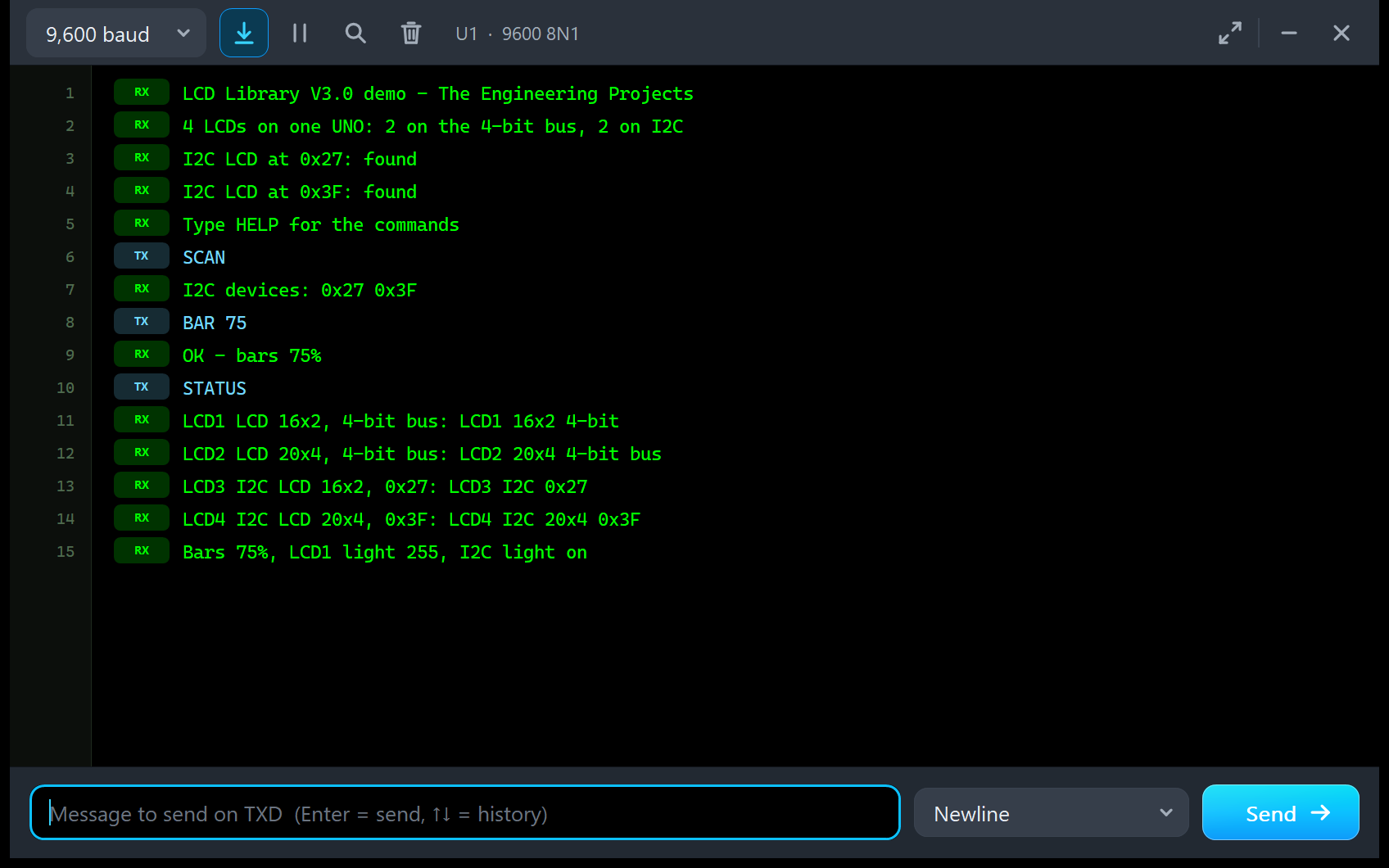
LCD Library V3.0 demo - The Engineering Projects
4 LCDs on one UNO: 2 on the 4-bit bus, 2 on I2C
I2C LCD at 0x27: found
I2C LCD at 0x3F: found
Type HELP for the commands
SCAN
I2C devices: 0x27 0x3F
BAR 75
OK - bars 75%
STATUS
LCD1 LCD 16x2, 4-bit bus: LCD1 16x2 4-bit
LCD2 LCD 20x4, 4-bit bus: LCD2 20x4 4-bit bus
LCD3 I2C LCD 16x2, 0x27: LCD3 I2C 0x27
LCD4 I2C LCD 20x4, 0x3F: LCD4 I2C 20x4 0x3F
Bars 75%, LCD1 light 255, I2C light on
At the start the sketch reports both backpacks, and SCAN finds exactly the two addresses on the bus. BAR 75 draws 15 full cells on row 4 of both 20x4s at once, and STATUS lists each LCD with its type and its first row.
One Command, Four LCDs
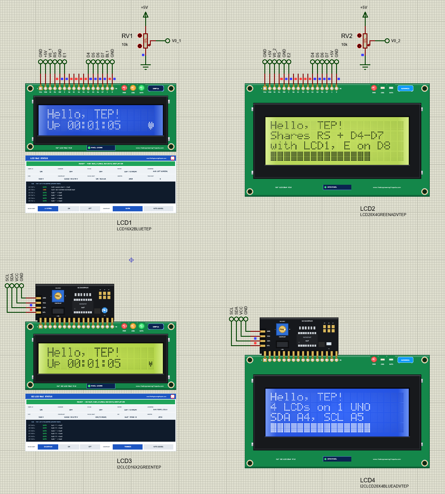
ALL writes its text on row 1 of every LCD, each padded to its own width. Two of the four writes go over the 4-bit bus, each with its own E pin, and two over I2C, each to its own address. Then the backlights:
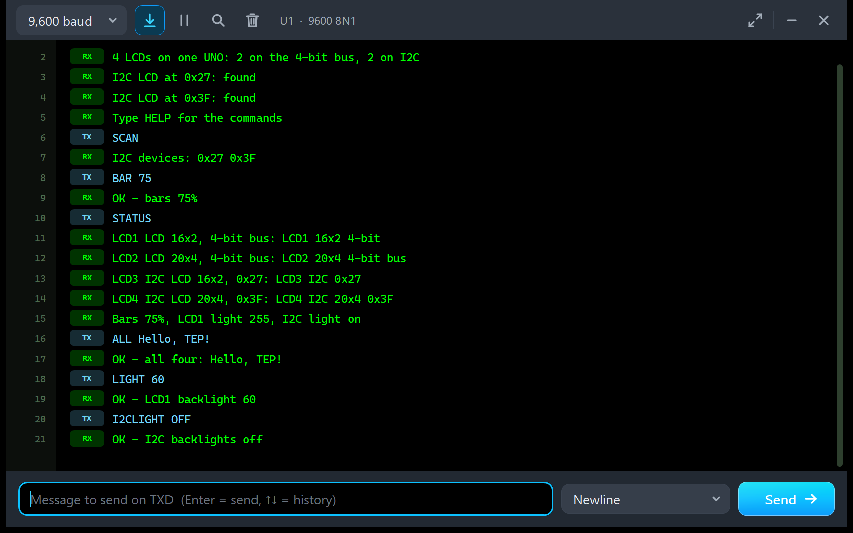
ALL Hello, TEP!
OK - all four: Hello, TEP!
LIGHT 60
OK - LCD1 backlight 60
I2CLIGHT OFF
OK - I2C backlights off
Two Kinds of Backlight
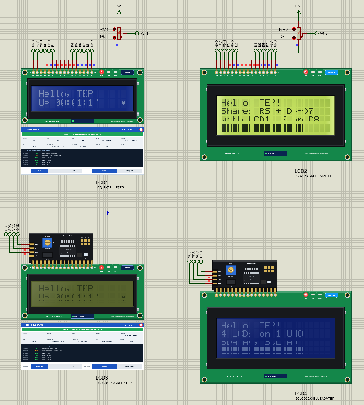
LIGHT 60 sets the PWM on D10 to 60 of 255, and our model averages the current like your eye does: about a quarter of the full 16.8 mA. I2CLIGHT OFF clears P3 on both backpacks, so LCD3 and LCD4 go dark; their characters stay in the controller and come back with I2CLIGHT ON. LCD2's backlight is wired to +5V and stays on.
Simple and Advance: Panels and Test Tools
In the showcase, LCD1 and LCD3 are Simple devices: their STATUS panel sits right under the board and shows the state in words (READY, NOT INITIALISED, TOO FAST, NO POWER), the flags, the address, the supply, the contrast and the backlight, and the last six transfers. LCD2 and LCD4 are Advance devices: they keep only the board on the schematic and open a pop-up window with the Display, Bus log and Tests tabs. Here is LCD2's Display page:
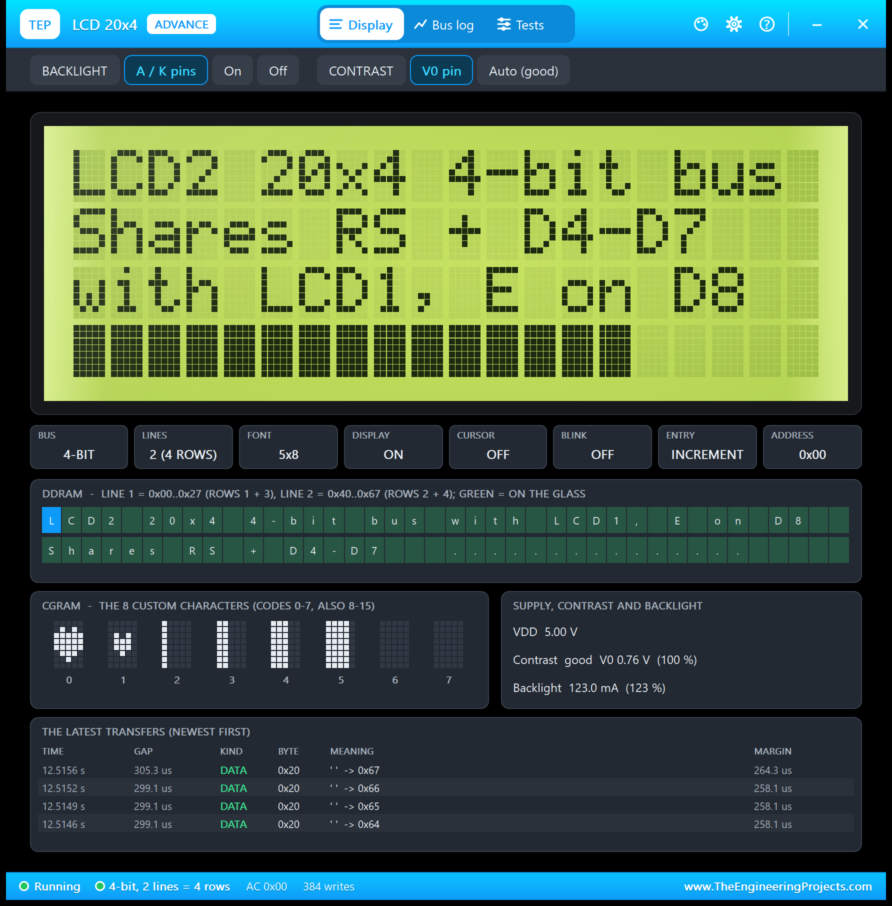
The DDRAM grid shows the row order of every 20x4: the controller's line 1 holds "LCD2 20x4 4-bit bus" and then "with LCD1, E on D8", which the glass shows on rows 1 and 3. The CGRAM shows the two hearts and the four bar steps of the sketch. The Tests tab has four tools on every Advance LCD:
| Tool | Good for | On |
|---|---|---|
| Init check | An LCD that stays blank or shows blocks: is the start-up right? | All Advance LCDs |
| Timing | Lost characters: is the sketch too fast for the controller? | LCD 16x2, LCD 20x4 |
| I2C bus | A blank I2C LCD: the address, the address checks, other devices, the clock | I2C LCD 16x2, I2C LCD 20x4 |
| Speed | Slow screens: how long a full line and a full screen take | All Advance LCDs |
| Characters | A symbol's code (the degree sign is 0xDF), the bytes for createChar() | All Advance LCDs |
In the showcase, LCD4's Init check shows the one-second wait of LiquidCrystal_I2C: its first command comes about 2.3 s after power-on, far more than the 40 ms the datasheet asks for, so it passes.
The Four Single-LCD Demos
The package also has the demos of the four single-LCD libraries, so you can study one LCD at a time. Each one runs on two UNOs, with a Simple LCD on NODE 1 and an Advance LCD on NODE 2, and each is explained step by step in its own article. They are the same projects as in those libraries, and they run unchanged on this DLL.
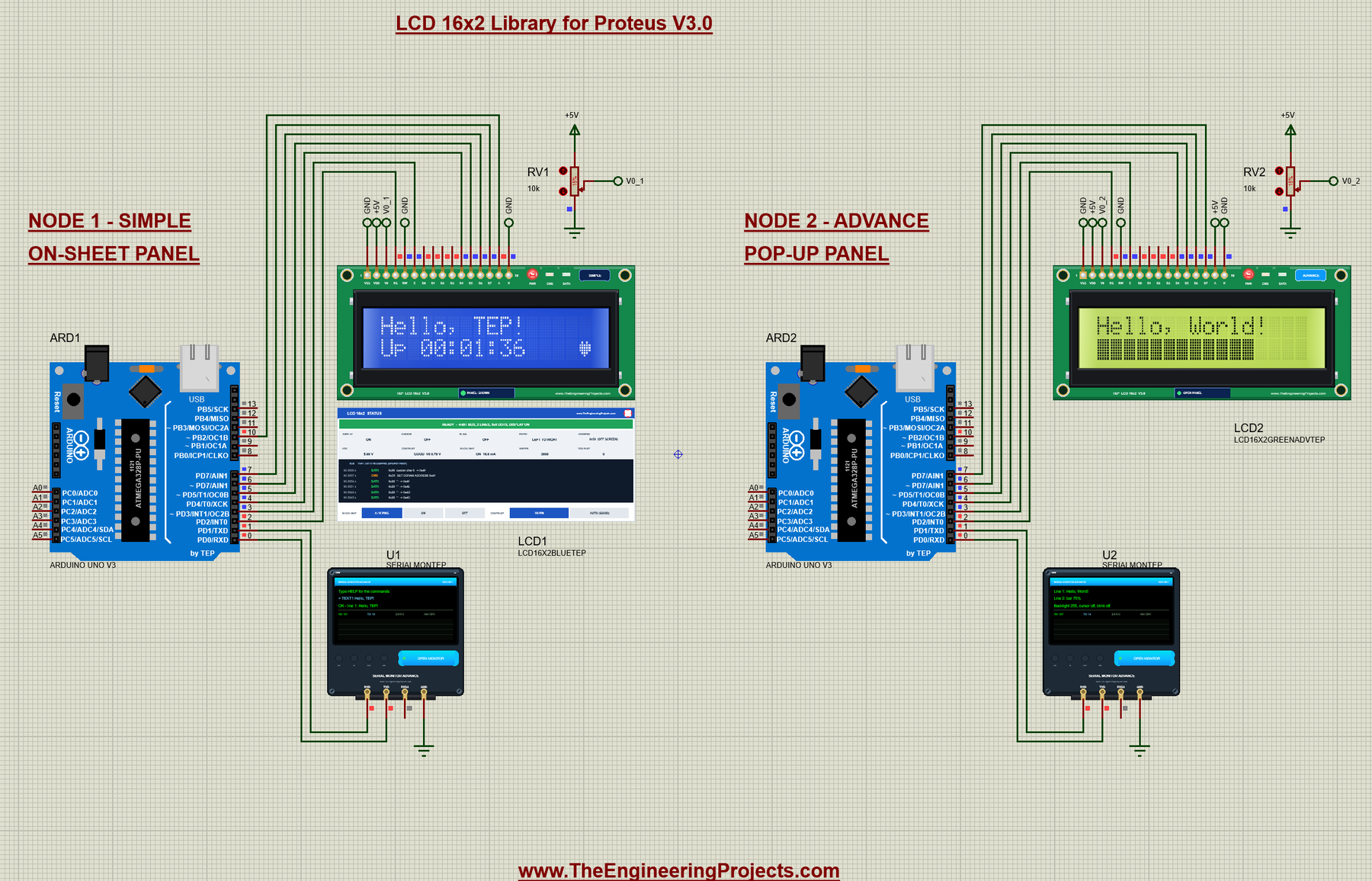
LCD 16x2: LiquidCrystal on the 4-bit bus, the contrast pot and the PWM backlight, with commands for both lines, a bar graph and scrolling. Read the LCD 16x2 Library for Proteus V3.0.
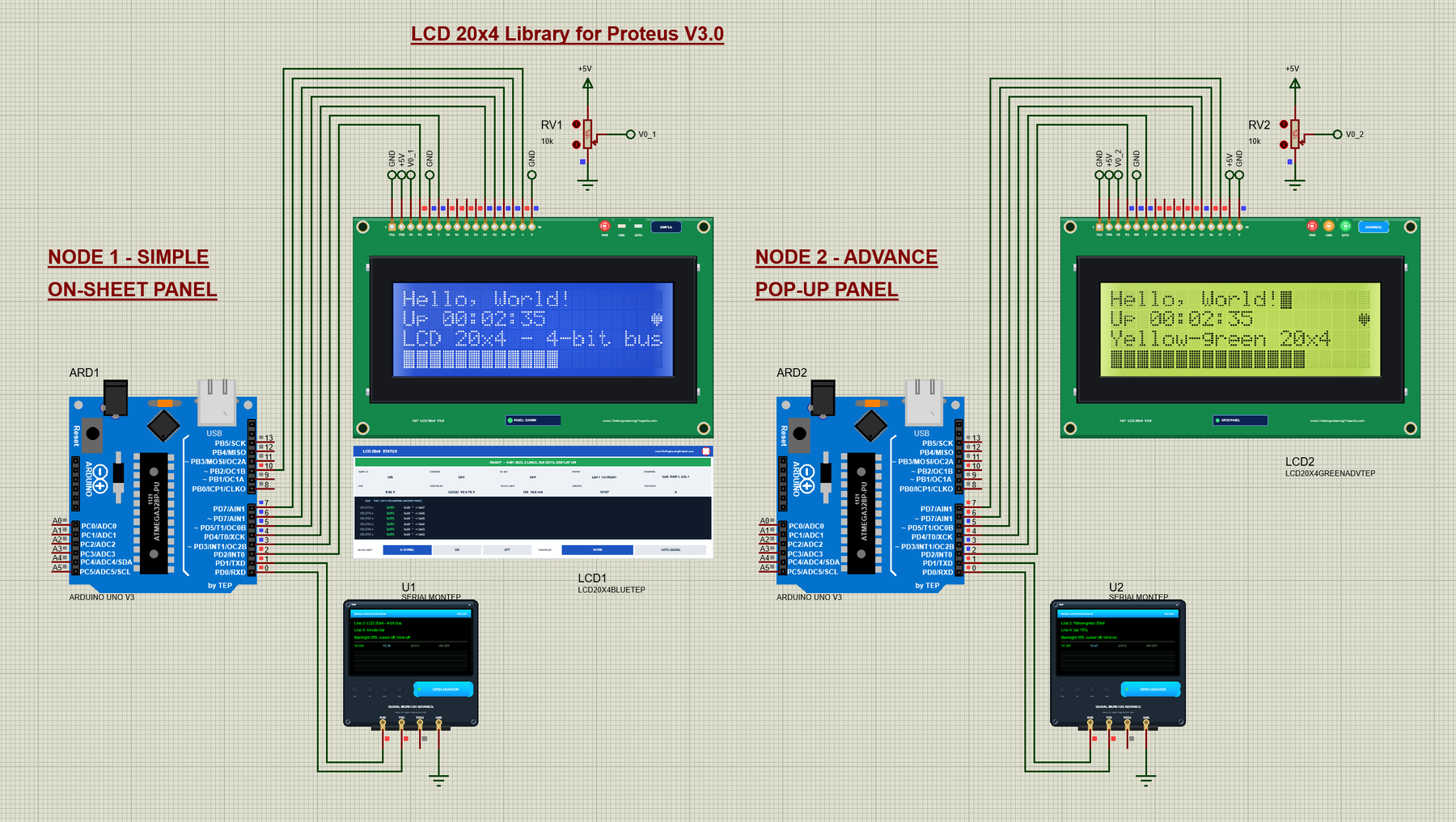
LCD 20x4: the four-row dashboard, the 20x4 row order (rows 1 and 3 swap places in a display shift) and the blocks on rows 1 and 3 before initialisation. Read the LCD 20x4 Library for Proteus V3.0.
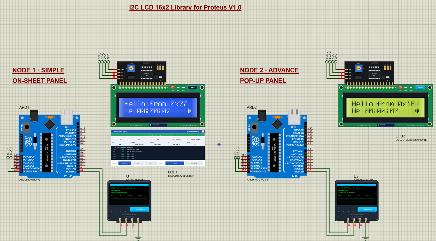
I2C LCD 16x2: two backpacks at 0x27 and 0x3F, each on its own UNO; each sketch finds its backpack's address by itself, and you can bridge the pads, turn the trimmer and pull the LED jumper. Read the I2C LCD 16x2 Library for Proteus V1.0.
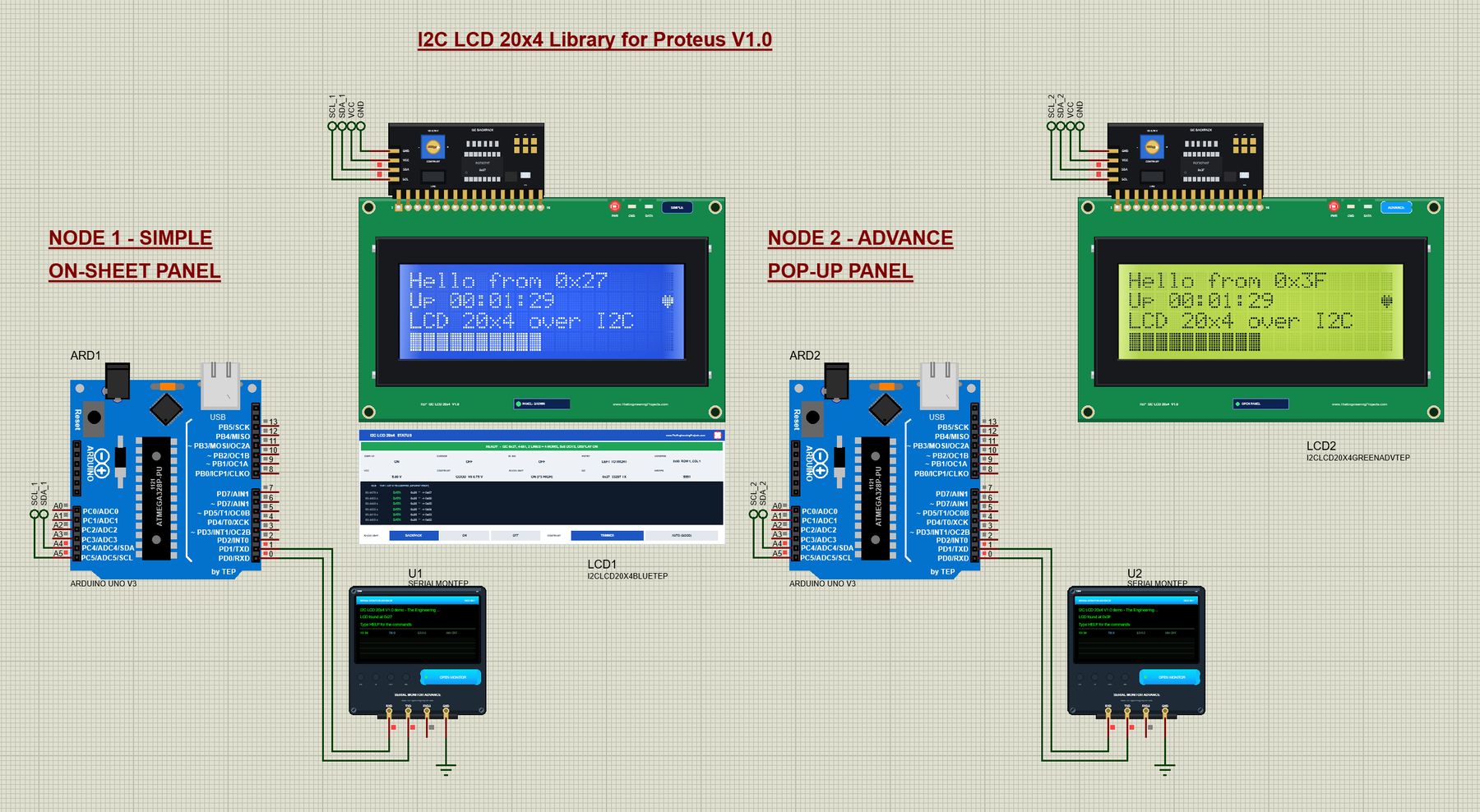
I2C LCD 20x4: the big LCD on just two wires, with the same backpack features and the 20x4 row order. Read the I2C LCD 20x4 Library for Proteus V1.0.
Troubleshooting
- Every part shows up twice in Pick Devices: a single-LCD library's LIB file is installed too. Delete it (step 4 of the installation).
- The part is not simulated, or there is no panel: TEPLCD.DLL is missing from MODELS and from the project folder, or an older TEPLCD.DLL is there; use the one from this package.
- Two parallel LCDs show the same text: they share their E pin. Give each LCD its own E.
- An I2C LCD stays blank: type SCAN. No address at all means SDA, SCL or VCC; another address than the one in your sketch means the wrong address in
LiquidCrystal_I2C lcd(...)(the Advance I2C bus test then says NOT this backpack). - Two I2C LCDs show the same text: both backpacks have the same address. Bridge a pad on one of them, or use a PCF8574T and a PCF8574AT, as in the showcase.
- Blocks on the top row (16x2) or on rows 1 and 3 (20x4): the sketch did not initialise the LCD; on an Advance LCD, run the Init check.
- Faint characters or dark blocks: the contrast. Turn the pot or the backpack's trimmer, or set CONTRAST AUTO (GOOD) on the panel.
- No monitor window: TEPSERIALMON.DLL is missing, or click OPEN MONITOR on the monitor.
Things to Know Before Using Real LCDs
The showcase sketch uses only LiquidCrystal, LiquidCrystal_I2C, Wire and Serial, so it runs on a real UNO with the same four LCDs too. Keep in mind:
- Contrast first: a blank LCD at power-on is very often just the contrast. Turn the pot or the trimmer until the blocks just show, then a little back.
- The backlight current: the blue backlight (about 20 mA) is fine on a PWM pin; a yellow-green one (about 120 mA) goes to 5V or a transistor, never to an Arduino pin.
- Check the address: many I2C backpacks come at 0x27, others at 0x3F. Run SCAN before you write the address into the sketch.
- A shared bus: keep the wires short; each extra LCD adds load to RS, D4 to D7, SDA and SCL.
- Speed: over I2C a full 20x4 screen takes about 125 ms, so update only what changed.
Limitations of the Simulation
- Not modelled: the 5x10 font on the glass, the A02 (European) ROM, the slow response of the liquid crystal, the LCD's current draw, the PCF8574's INT output and clock stretching.
- The PWR, CMD and DATA LEDs, the badges, the panel buttons, the STATUS panels and the pop-ups are TEP additions; a real board has only its backlight.
- The model is our own implementation, written from the HD44780 and PCF8574 datasheets; HD44780 is a Hitachi part and PCF8574 an NXP / TI part, and this library is not made or endorsed by them or by Labcenter.
- Licences: the demo sketches use Arduino's LiquidCrystal 1.0.7, LiquidCrystal_I2C 1.1.2 and Wire. The HEX files contain them and the Arduino AVR core 1.8.6, which include LGPL-licensed code; their source code is on GitHub.
- Tested in Proteus 8.5 in October 2026 (the showcase as shipped: all four LCDs, SCAN, ALL, BAR, LIGHT, I2CLIGHT, STATUS, the panels, both pop-ups and every screenshot here; about 0.66 x real time with both pop-ups and the monitor open; the four single-LCD demos re-run on the same DLL) and with automatic PC checks, 0 failed: 49 with the real showcase sketch against four LCD models at once, 7,202 on the HD44780 controller, and the showcase project read back from disk. Proteus 7 is not supported.
So, that was all about the LCD Library for Proteus V3.0. I hope having all four LCDs in one library, and seeing four of them run on one Arduino, makes your next display project much easier. If you use the LCD Library for Proteus in a project, please share your feedback in the comments or in our forum, and if you have any questions, ask in the comments and I will help you out. Till the next tutorial, take care and have fun!