Hello friends, I hope you all are doing great. Today, I am going to share the new 5 mm LED Library for Proteus. Proteus has LEDs of its own, little symbols with a triangle and two arrows. They do the job, but they look nothing like the part on your bench. So we drew the real thing: the moulded dome, the two metal frames you can see inside it, the rim with its flat, and two thin legs, in six colours.
5 mm LED Library for Proteus
Latest version: V1.0 (November 2026, this tutorial)
Other component libraries: C945 Transistor · PC817 Optocoupler · Relay Module · Resistor · Designer Colour LED · Push Button · Active Buzzer · Electrolytic Capacitor · Ceramic Capacitor · Tantalum Capacitor · Film Capacitor · 1N4007 Diode · Zener Diode · Schottky Diode · Supercapacitor · Photodiode · RGB LED · Bridge Rectifier · Flashing LED · Bi-Colour LED · SMD LED · Slide Switch · Toggle Switch · Rocker Switch · Micro Limit Switch · Emergency Stop Switch · SMD Resistor · Power Resistor · Resistor Network · Potentiometer · Trimmer Potentiometer · Slide Potentiometer · NTC Thermistor · DIP Switch · Fuse · Passive Buzzer · Mini Speaker · 7-Segment Display · LED Bar Graph · IR / UV LED · Small Transistors · TIP122 Darlington · N-MOSFET · P-MOSFET · PC817 Optocoupler · Filament Bulb · Power LED · Voltage Regulator · SCR and TRIAC · Inductor · Toroid Inductor · Crystal
Helping Tools
- Serial Monitor Advance: a serial terminal window for the UART of your board
- Serial Monitor Expert: the serial monitor with extra debugging tools
- LCD Library for Proteus V3.0: 16x2, 20x4 and I2C LCDs to show your readings
These LEDs are drawn to true scale against our Arduino, so a sheet full of them stays neat. They glow with their current, PWM dims them, and too much current burns them out, just like the real ones. Click one while the simulation runs and a pop-up shows the current, the voltage, the brightness, the PWM it sees, and the series resistor you need for your supply.
NOTICE: Our team has put a lot of effort into these small parts: the bodies, the animation and the pop-ups are all our own design, and you get them free. Your feedback is the fuel that keeps us going, so please tell us what you think in the comments below or in the 5 mm LED board of our forum. And if our free libraries help you, you can buy us a coffee. So, let's get started with the 5 mm LED Library for Proteus:
What is an LED?
LED stands for Light Emitting Diode. Like any diode it lets current flow one way only, from the anode to the cathode. What makes it special is the tiny crystal at its heart, called the die. When current crosses the junction in that crystal, the energy comes out as light. The material of the die decides the colour, so a red LED and a blue LED are built from different stuff.
That is also why each colour needs a different voltage. Blue light carries more energy than red light, so a blue LED needs a higher forward voltage before it conducts. Our models use the usual values for a 5 mm part at 20 mA:
| Colour | Forward voltage at 20 mA | Device |
|---|---|---|
| Red | 2.0 V | LED5MMREDTEP |
| Orange | 2.05 V | LED5MMORANGETEP |
| Yellow | 2.1 V | LED5MMYELLOWTEP |
| Green | 2.2 V | LED5MMGREENTEP |
| Blue | 3.1 V | LED5MMBLUETEP |
| White | 3.2 V | LED5MMWHITETEP |
Why an LED Needs a Resistor
This is the one rule that every beginner has to learn, usually by burning a few LEDs. Once an LED is conducting, its voltage hardly changes, whatever the current does. A tiny rise in voltage makes a huge rise in current. So if you connect an LED straight to 5 V, nothing limits the current, and it dies in a moment.
The fix is a series resistor. It takes whatever voltage the LED does not want, and by doing so it sets the current. The sum is simple:
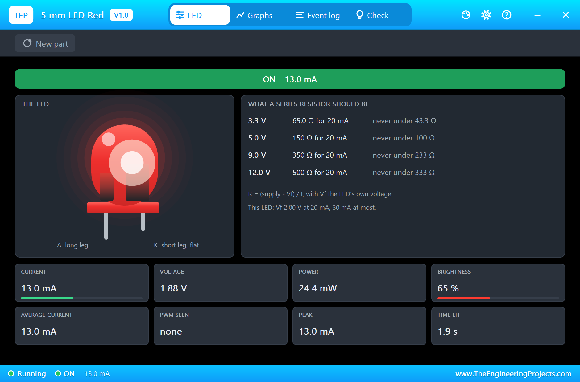
R = (supply voltage - LED voltage) / currentFor a red LED on 5 V at 20 mA, that is (5 - 2) / 0.02 = 150 ohms. A little more is fine, and most people use 220 ohms because it is common and gives a comfortable 13 mA. Our pop-up works this out for you, for 3.3, 5, 9 and 12 V, and also tells you the smallest value that stays inside the limit.
Why not just pick a resistor that gives exactly 30 mA, the limit? Because a limit is not a target. Parts differ, supplies rise and rooms get warm, so a design should leave room. An LED at 10 to 15 mA is already bright, it runs cool, and it will last for years. Our pop-up shows both numbers for that reason: the value that gives a healthy 20 mA, and the smallest value you should never go below.
Which Leg is Which?
A new LED has one leg longer than the other. The long leg is the anode, and it goes towards the positive side. There is a second clue if the legs have been cut: the rim of the plastic has a small flat on the cathode side. Our symbol has that flat too, on the right, over the K leg. Look inside the dome of a real LED and you will see the two metal frames. The larger one, shaped like an anvil, is usually the cathode, and it holds the die in a little cup.
How PWM Dims an LED
An Arduino pin has only two states, HIGH and LOW, so how can it dim an LED? It switches the LED on and off very quickly, and your eye averages the result. This is PWM, and the share of time spent on is the duty cycle. At 50 % duty, the LED looks about half as bright. analogWrite() does this for you on the pins marked with a wave. Our model has the same lag as your eye, so a PWM signal really does dim it on the sheet.
Features of the 5 mm LED Library for Proteus
- The real look, at true scale: the dome, the metal frames inside, the rim with its flat and two legs 2.54 mm apart, with our small TEP signature on the rim.
- Six colours: red, orange, yellow, green, blue and white, each with its own forward voltage.
- A real diode: the diode law with a series resistance, in the analog simulator.
- It glows with its current: the dome lights up from the die, in steps, and PWM dims it.
- It burns out: well over its 30 mA limit, the die overheats, the dome goes dark and scorched and the circuit opens.
- A reverse warning: connect it backwards and it stays dark, and the pop-up says REVERSED.
- A pop-up for every LED: click it at Run for the glow, the series resistor for four supplies, eight live values, graphs, an event log and a check page.
- A complete package: about 1.5 MB with the library, our Arduino UNO V4.0, the demo's resistors and the demo, without the source code of the models.
The 5 mm LED in Proteus
The six devices are in TEPLED5MM.LIB, under Optoelectronics, LEDs, with the prefix D. They all run on one model, TEPLED5MM.DLL. Search LED5MM in Pick Devices. The pins are A and K, and they stand 100 thou apart, the real 2.54 mm pitch, so they sit right on the Proteus grid.
The Properties
| Property | What it does |
|---|---|
| Forward voltage at 20 mA, V | the voltage of the part; each colour has its own by default |
| Maximum current, mA | the limit, 30 mA by default; over it the die starts to heat |
Download 5 mm LED Library for Proteus
Click the button below to download 5mm-LED-Library-for-Proteus-v1.0.zip (about 1.5 MB, without the source code of the models):
5 mm LED Library for Proteus V1.0- README.txt: installation, the demo, the properties, troubleshooting and the limits.
- Proteus Library Files:
TEPLED5MM.LIB,TEPRESISTOR.LIBand ourArduinoV4TEP.LIB. - Proteus Model Files:
TEPLED5MM.DLL,TEPRESISTOR.DLLandTEPARDUINO.DLL. - Arduino Code: the demo sketch.
- Proteus Simulation: the demo project, its HEX file and copies of the DLLs.
No Proteus yet? Read How to Download and Install Proteus 7 and 8. New to libraries? Follow How to Install a New Library in Proteus.
How to Install 5 mm LED Library for Proteus
- Close Proteus and extract the whole zip file, for example to your Desktop.
- Copy the files from Proteus Library Files into the LIBRARY folder of Proteus.
- Copy the files from Proteus Model Files into the MODELS folder.
- Delete
TEPLED5MM.IDXfrom the LIBRARY folder if it is there. - Start Proteus, press P and search for LED5MM.
Demo: Six Colours and a Test Bench
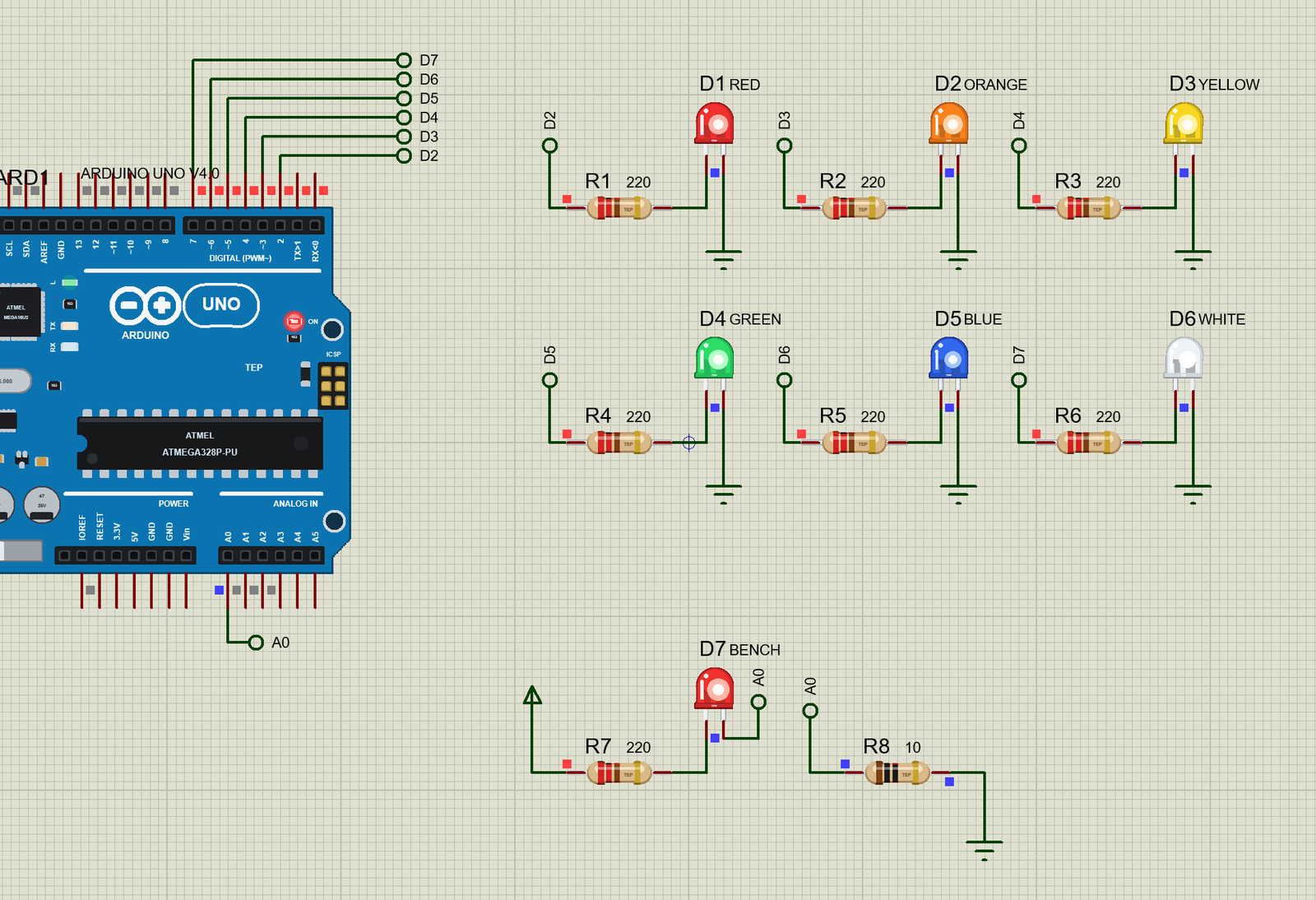
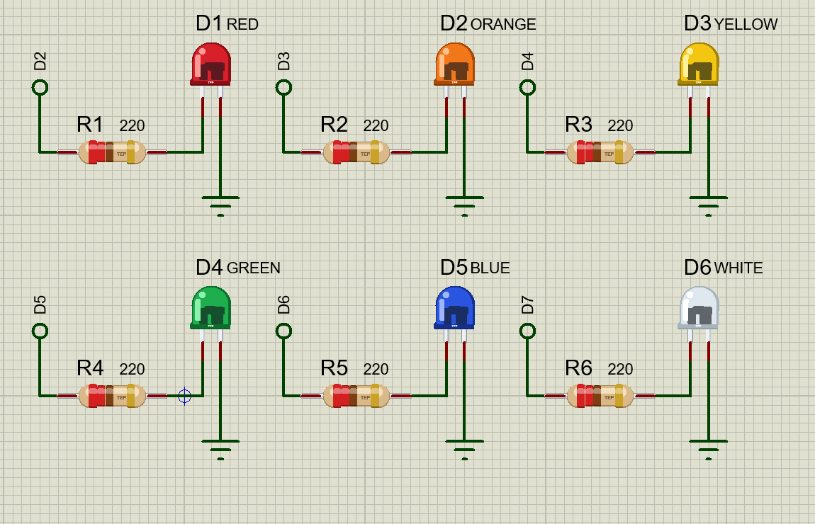
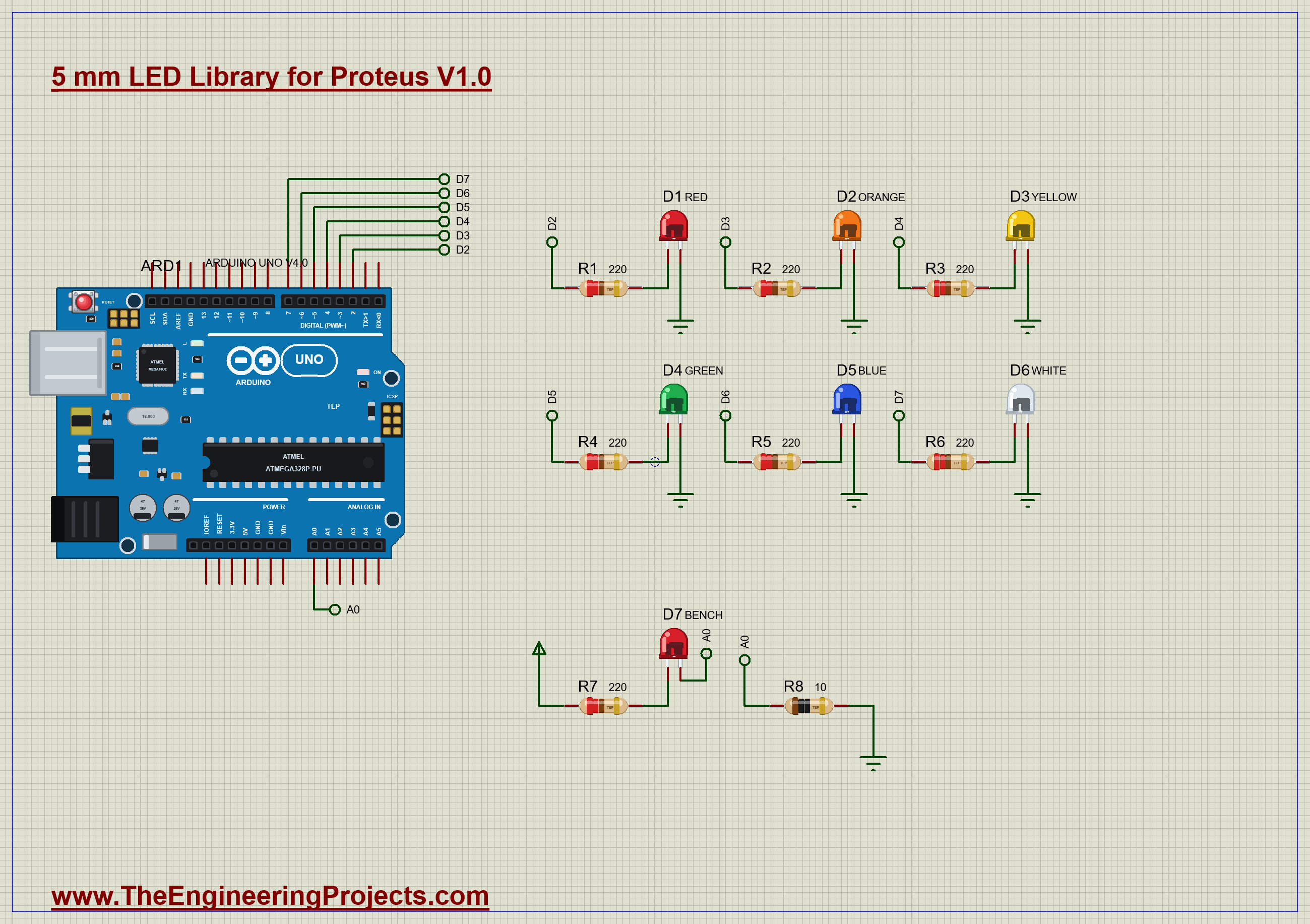
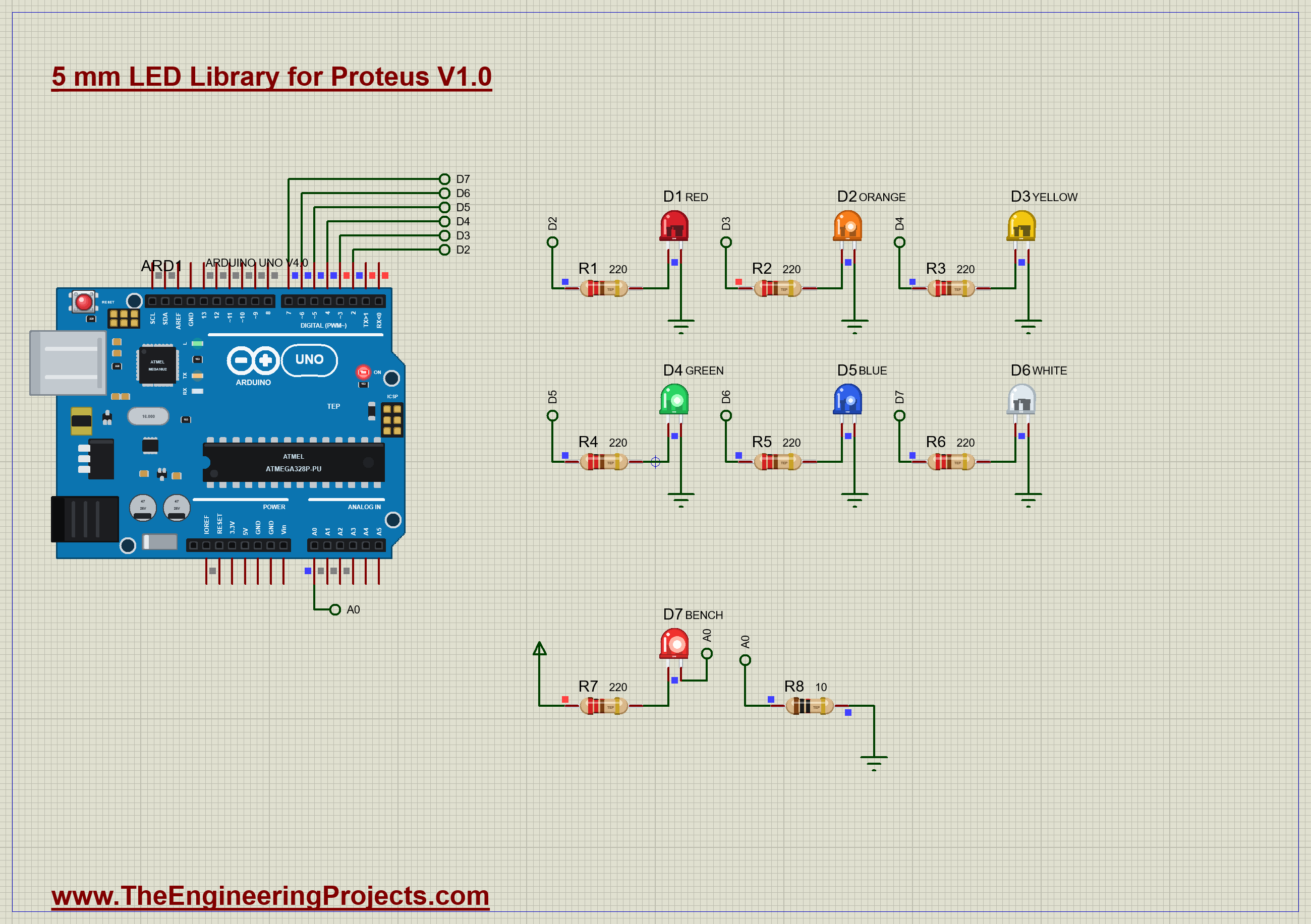
The demo has two parts. Six LEDs show off the colours, with chase, all-on and fade patterns from the Arduino. A seventh LED sits on a little test bench, where we measure its current and push it until it fails. Open LED-Colours-ArduinoUnoV4.pdsprj. It runs on our Arduino UNO Library for Proteus V4.0, and the results appear in its built-in monitor, the same window as our TEP Serial Monitor Advance for Proteus. The resistors are the real-looking parts from our Resistor Library for Proteus, and they are in the zip file too.
| Part | Connection | Job |
|---|---|---|
| D1 to D6 | D2 to D7, each through 220 ohms | the six colours |
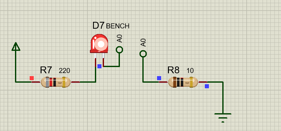
| R7 | +5V to D7's anode, 220 ohms | the resistor we will step down |
| D7 | R7 to A0 | the LED on the bench |
| R8 | A0 to GND, 10 ohms | the current sense resistor |
The Patterns
The sketch keeps its six pins in an array, so a pattern is just a small loop. The chase moves one lit LED along the row, and it uses millis() rather than delay(), so the sketch can listen to the monitor all the time:
void chase() {
  digitalWrite(LEDS[step], LOW);
  step = (step + 1) % 6;
  digitalWrite(LEDS[step], HIGH);
}
The fade uses PWM on the three pins that have it here. One LED brightens as the other fades, and the level bounces between 0 and 255:
void fade() {
  level += direction;
  if (level >= 255 || level <= 0) {
    direction = -direction;
    level = constrain(level, 0, 255);
  }
  analogWrite(3, level);
  analogWrite(5, 255 - level);
  analogWrite(6, level);
}
The Test Bench
R8 is a small sense resistor under the LED. All of the LED's current goes through it, so the voltage across it tells us the current by Ohm's law. With 10 ohms, 20 mA makes 0.2 V, which the Arduino reads easily on A0. If current was flowing and then it stops, the LED has failed:
  float volts = sum / 16.0 * 5.0 / 1023.0;
  float mA = volts / R_SENSE * 1000.0;
Run the Demo
Press Run. The LEDs chase, and the monitor shows the bench:
5 mm LED demo - The Engineering Projects
Commands: chase | all | fade | off
D7: 13.7 mA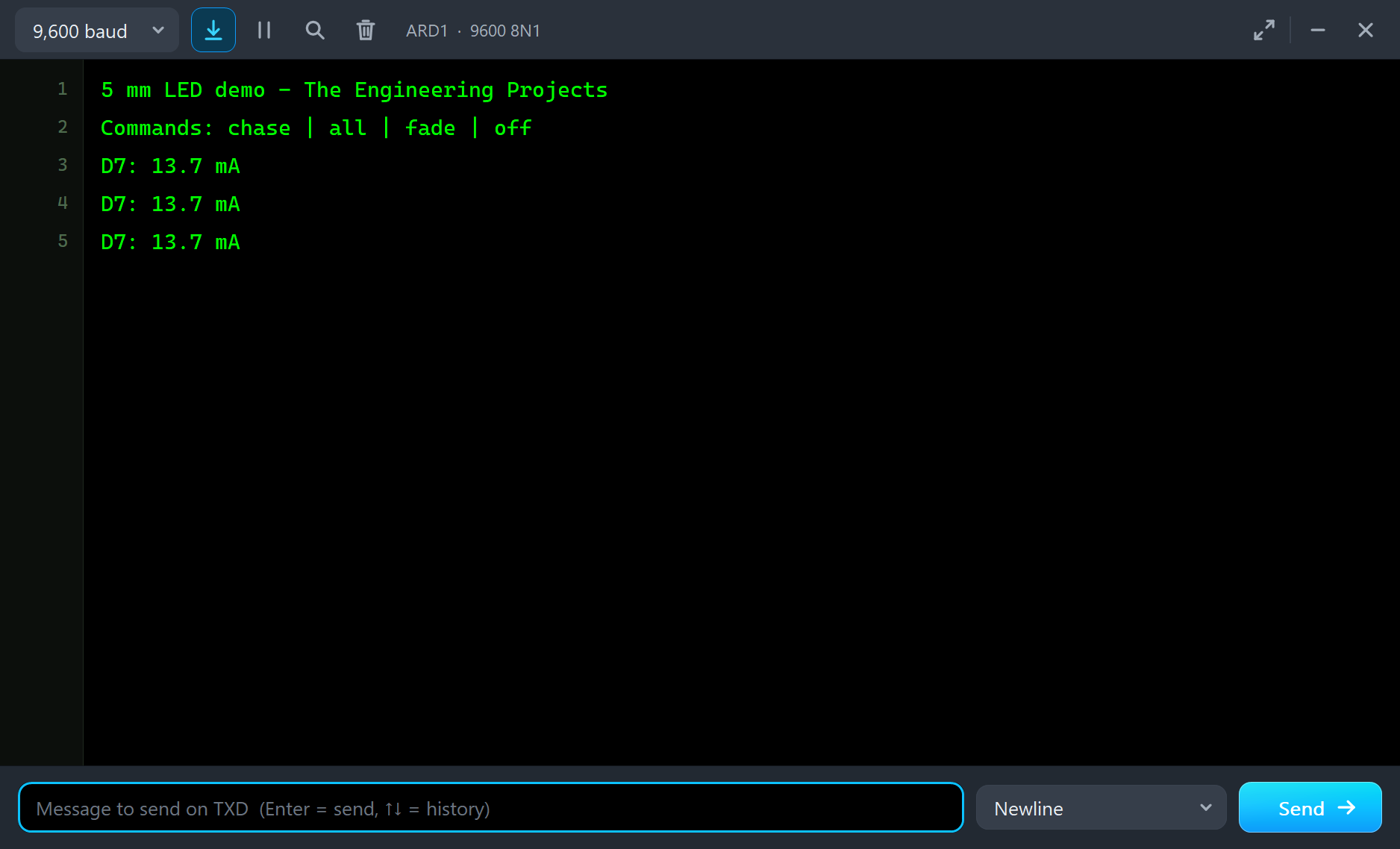
All On
Type all and press Send. Here is the complete circuit, truly running, with every LED lit:
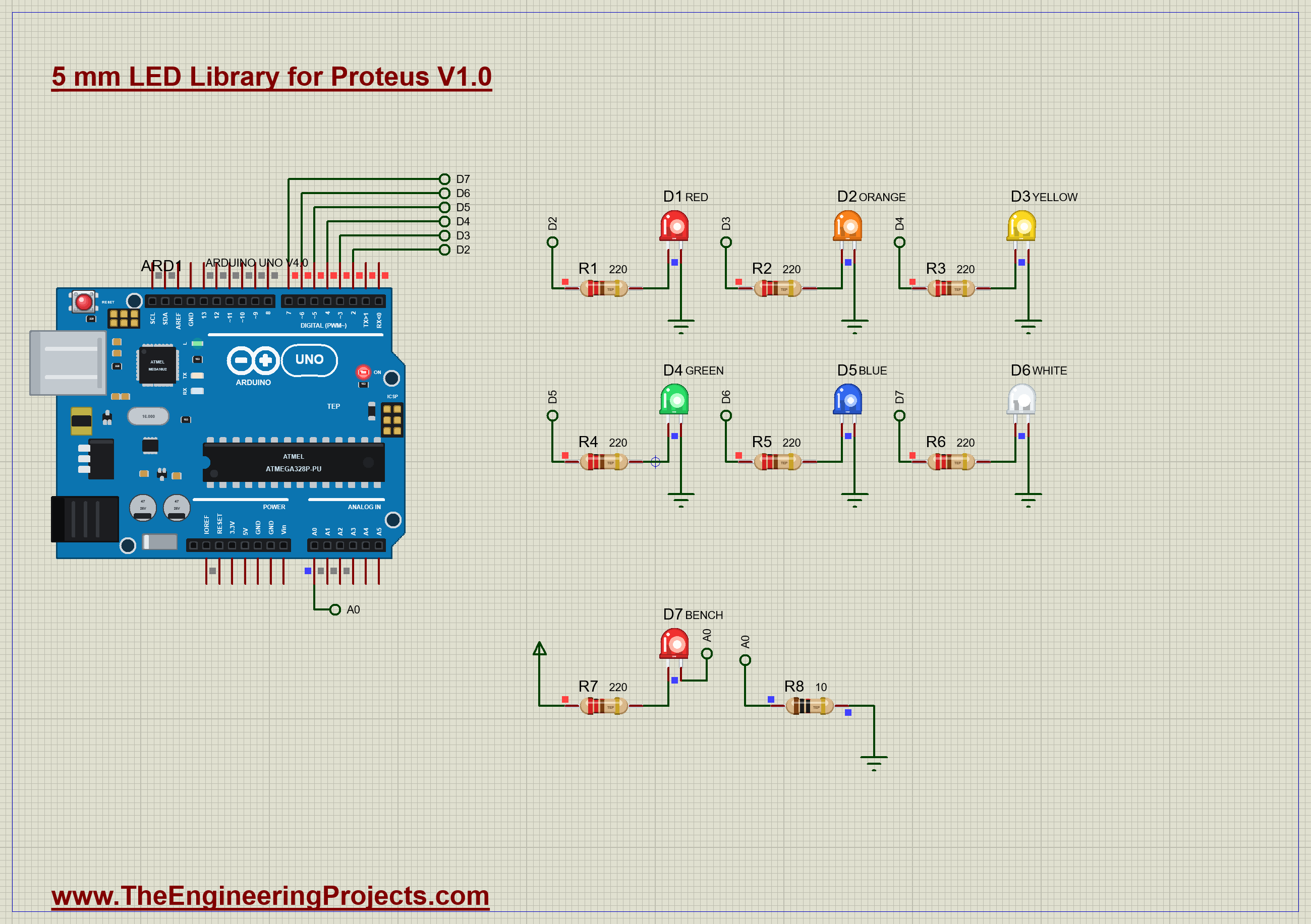
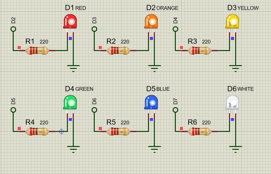
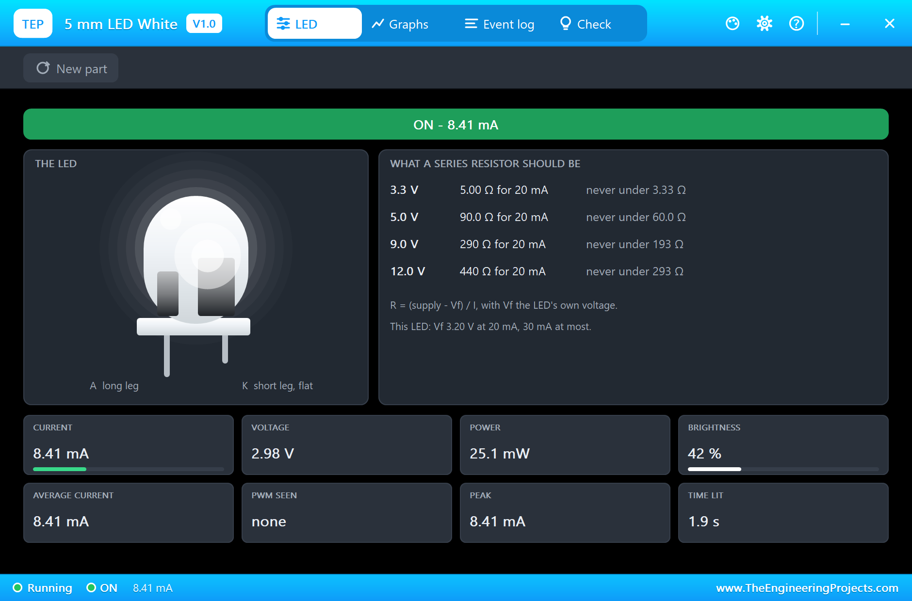
Now look closely at the numbers. The Arduino gives each LED the same 5 V through the same 220 ohms, yet they do not all draw the same current. Red has the lowest forward voltage and takes 13.0 mA. Blue and white need about 3 V, so less voltage is left across the resistor, and they take only about 8.6 mA. That is the sum from earlier, working exactly as it should.
The Pop-Up
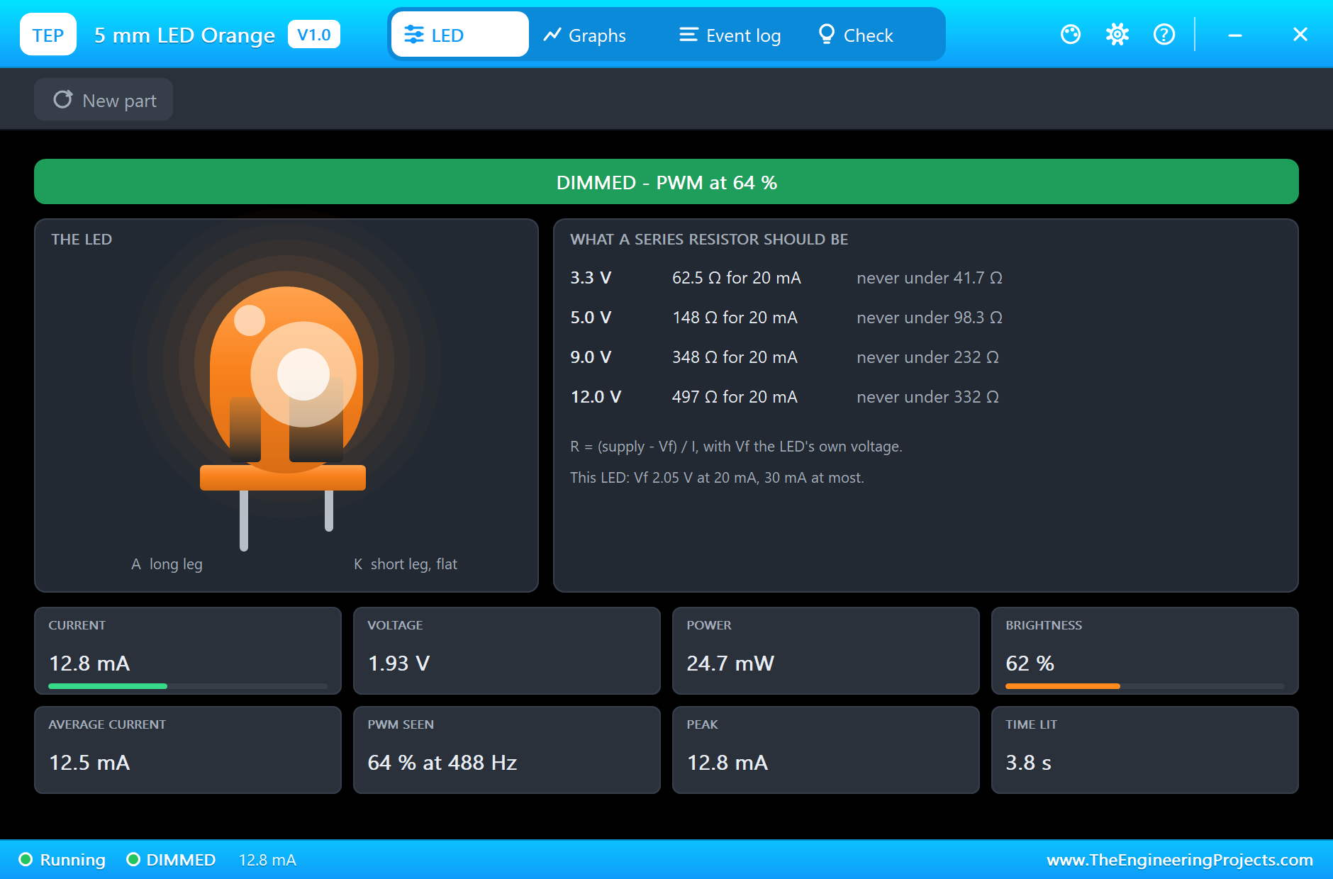
Click the dome of an LED. A sheet can hold a lot of LEDs, so the pop-ups stay closed until you ask for one. The LED tab shows the state, the part with its glow, the series resistor for four supplies, and the live values:
Fade
Type fade. Orange, green and blue start to breathe, while the others go dark. Click an orange LED and the banner says DIMMED, with the duty cycle and the frequency it measures from the current. The UNO's PWM runs at about 490 Hz on D3, and about 980 Hz on D5 and D6:
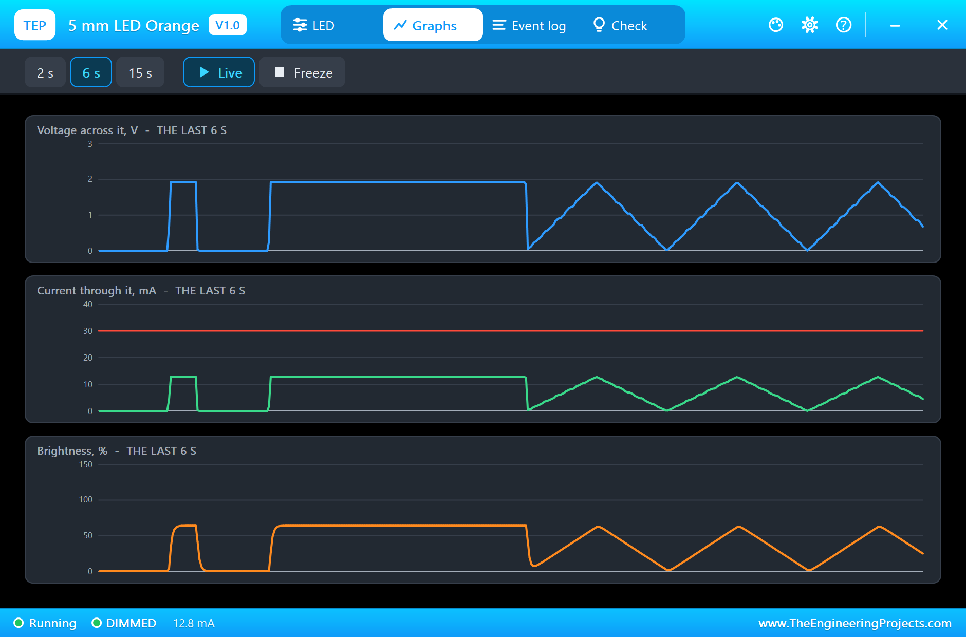
The Graphs tab shows the brightness rising and falling. Notice that the current is really a fast square wave, and the smooth curve is what your eye makes of it:
Stress the Bench
Now let's find out how much an LED can take. Type chase to free up the view, click R7 and press E12 down on its pop-up. Each press swaps it for the next smaller value, and the LED gets brighter. Here are the numbers from our run:
| R7 | Current | LED voltage | What happens |
|---|---|---|---|
| 220 ohm | 13.5 mA | 1.89 V | fine |
| 180 ohm | 16.1 mA | 1.93 V | fine |
| 150 ohm | 18.9 mA | 1.98 V | about the rated 20 mA |
| 120 ohm | 22.7 mA | 2.04 V | fine |
| 100 ohm | 26.3 mA | 2.10 V | close to the limit |
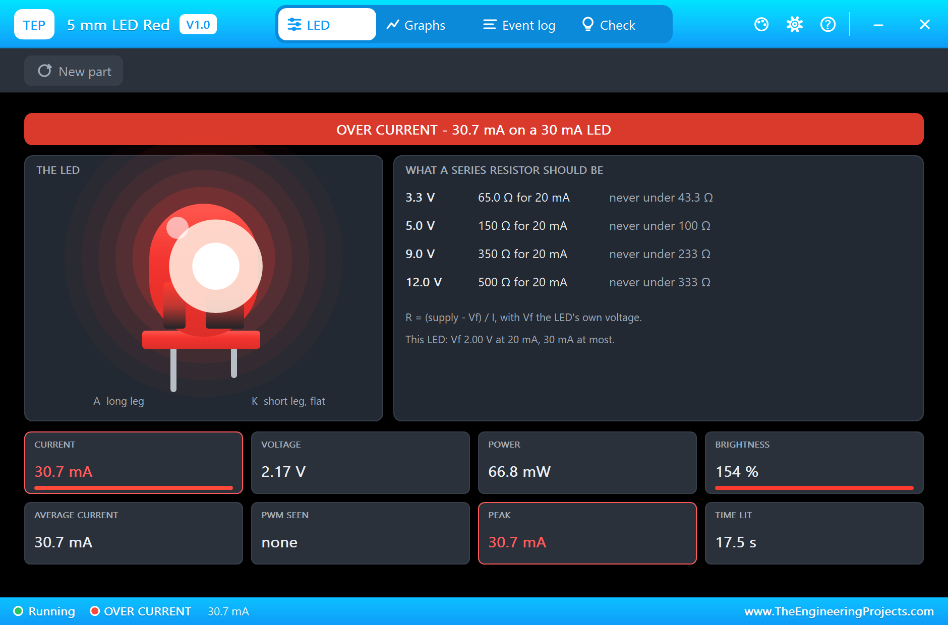
| 82 ohm | 30.7 mA | 2.17 V | OVER CURRENT |
| 68 ohm | 35.3 mA | 2.24 V | OVER CURRENT |
| 56 ohm | 40.5 mA | 2.32 V | OVER CURRENT |
| 47 ohm | 45.6 mA | 2.40 V | OVER CURRENT |
| 39 ohm | 51 mA | over 2.4 V | it burns out |
See how the LED's voltage only climbs from 1.89 V to 2.40 V while the current more than triples. That is the steep curve of a diode, and it is the reason a resistor must set the current. Past 82 ohms the banner turns red:
Burn It Out
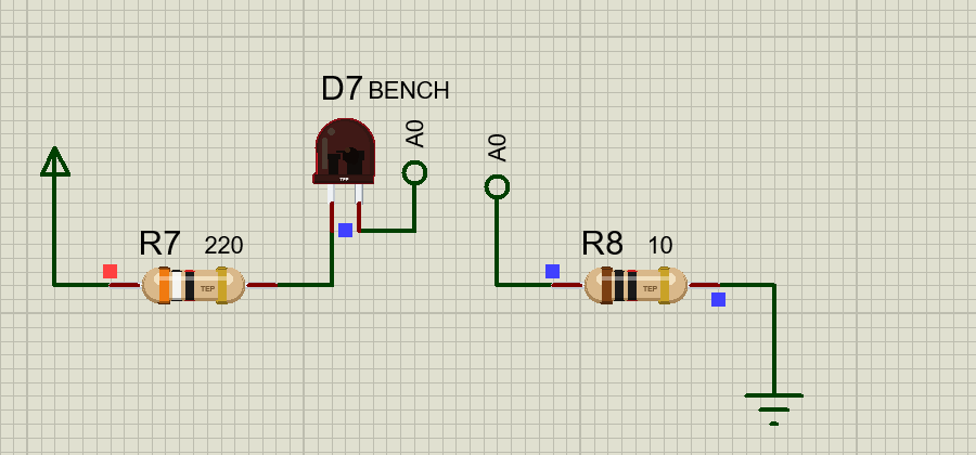
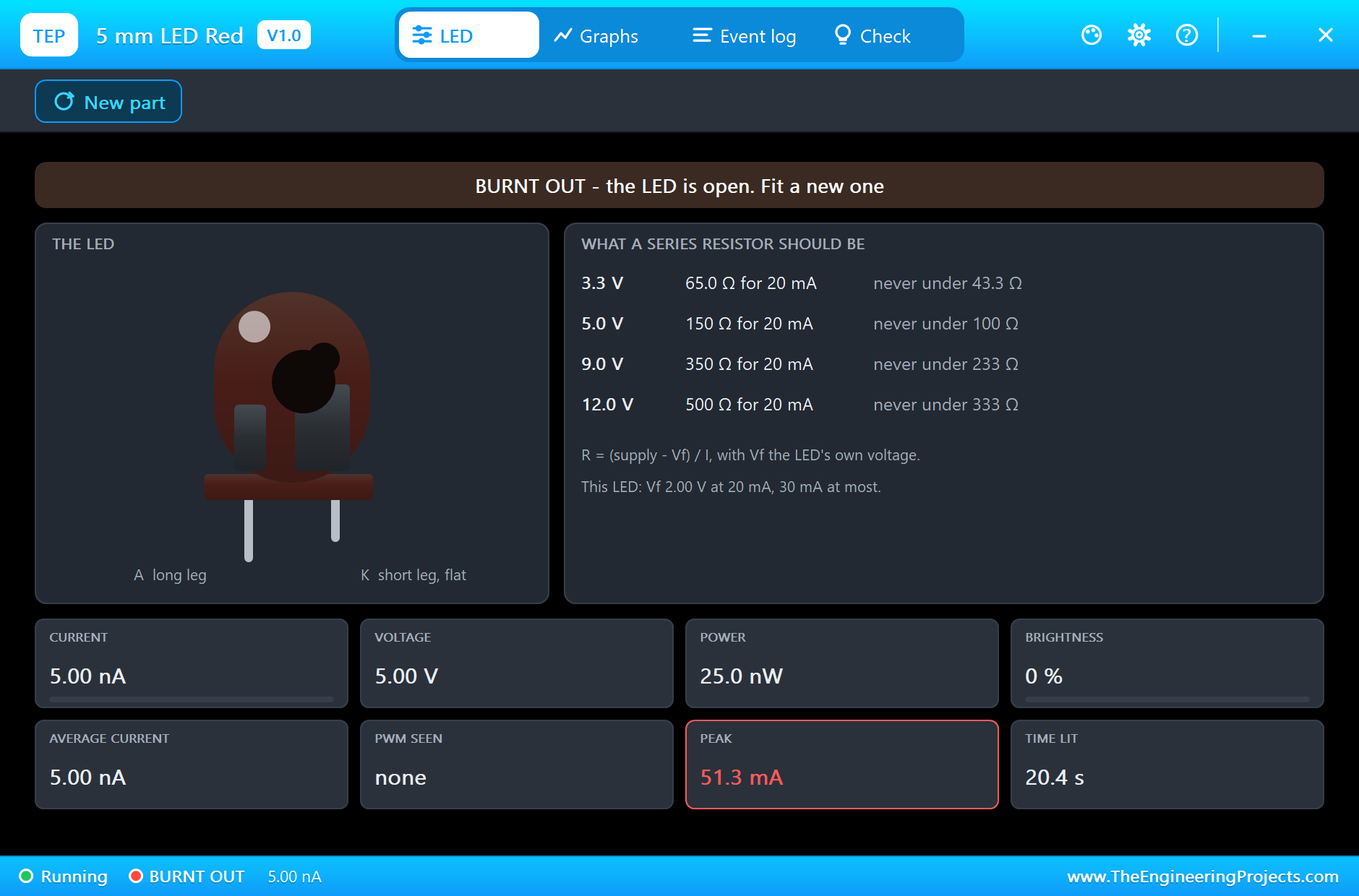
Keep going. At 39 ohms the current reaches 51 mA, far past the limit, and the die heats up quickly. When it fails, it opens, the current drops to nothing, and the monitor catches it:
D7: 45.5 mA OVER 30 mA
D7 BURNT OUT: no current on A0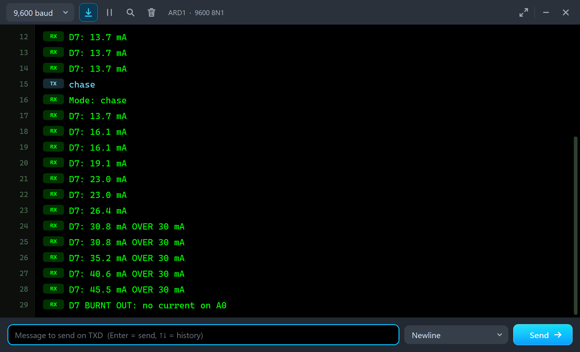
The Graphs and the Log
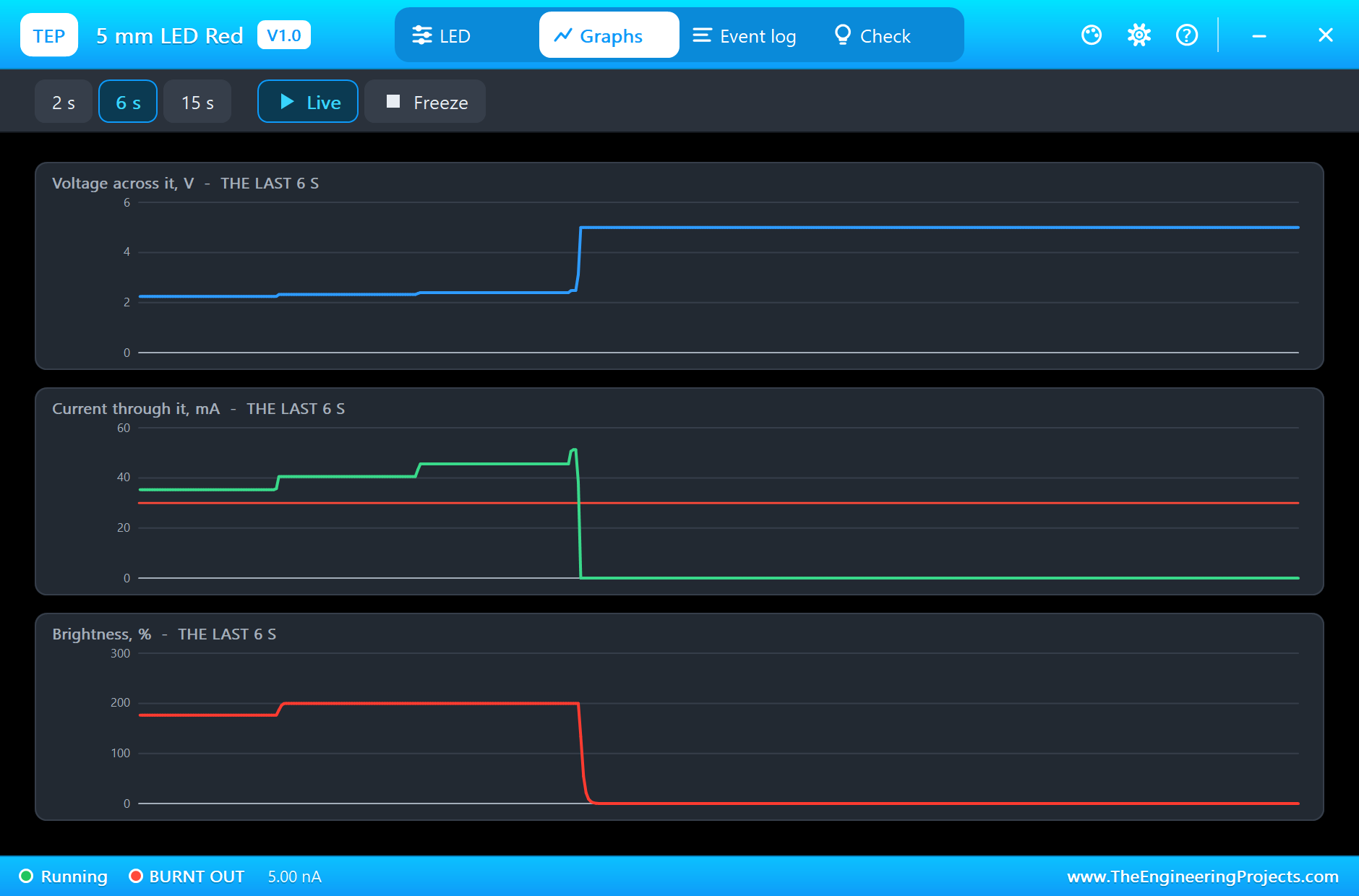
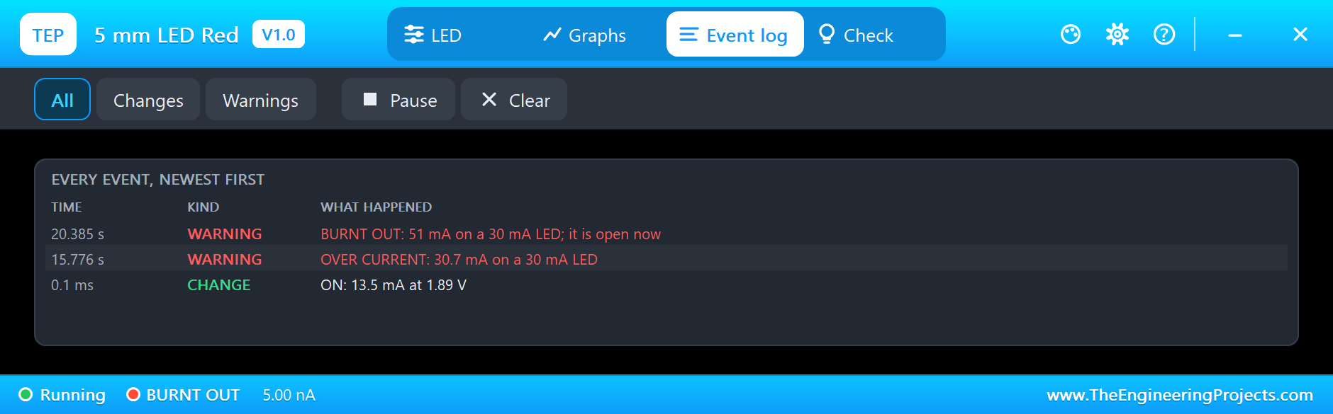
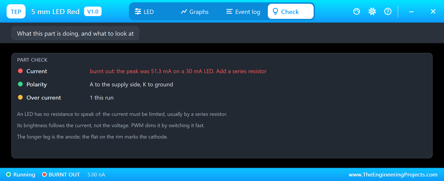
The Graphs tab shows the last moments of D7: the current climbing in steps past the red limit line, and then the end. The Event log keeps the whole story with the time of each step, and the Check page gives its verdict, with the advice that would have saved the LED:
Fit a New Part
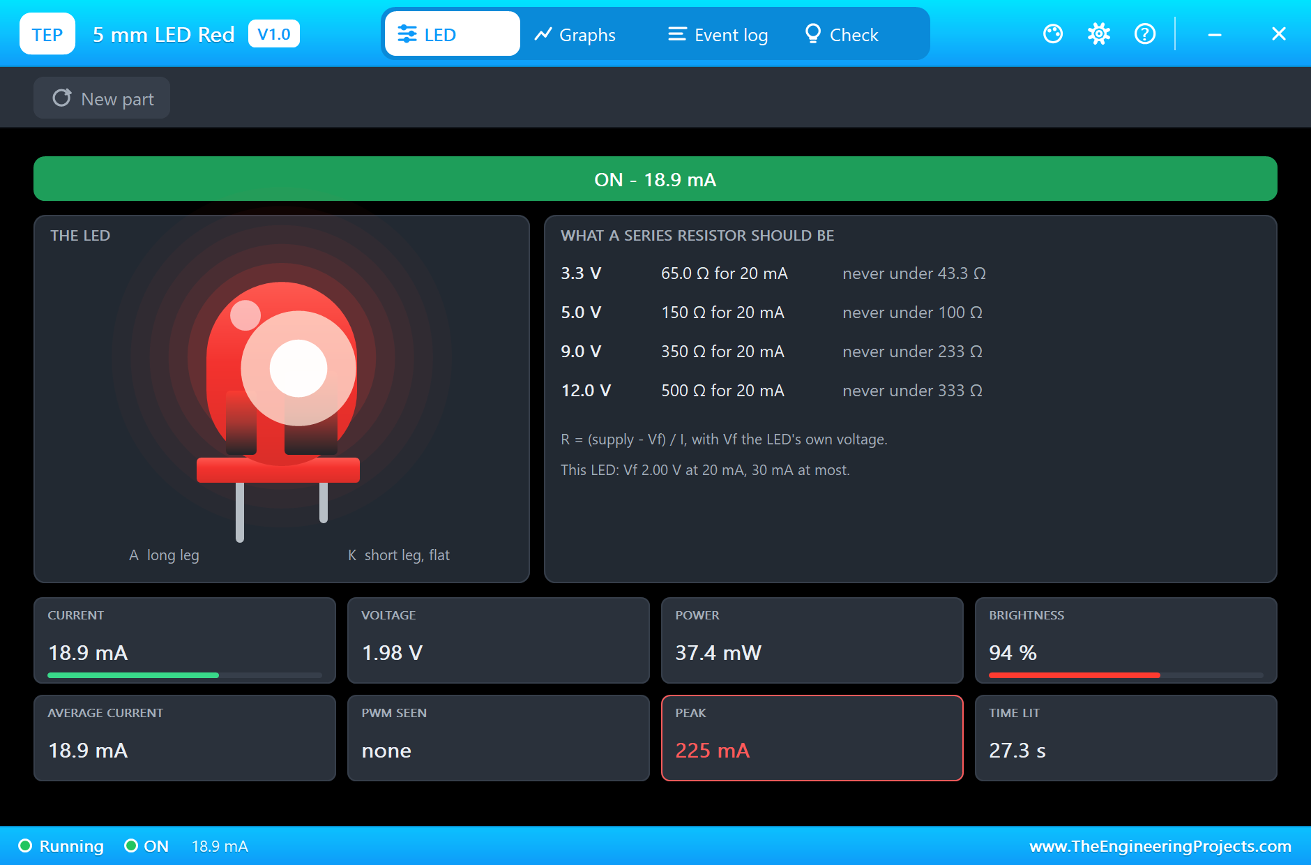
A burnt LED stays burnt. Press New part on its pop-up, or press Stop and Run. Be quick to bring R7 back up with E12 up on the resistor's pop-up, or the new one will go the same way. At 150 ohms D7 is back at a healthy 18.9 mA:
Try It Yourself
- Swap the anode and cathode of an LED, and read the pop-up.
- Work out R for a blue LED at 15 mA on 5 V, set it, and check the answer in the pop-up.
- Change the chase speed in the sketch, and find where it starts to look like a solid line.
- Add a seventh LED to the chase. Remember that the array and the loops need to grow.
- Set the maximum current property of D7 to 20 mA, and see how soon the warning comes.
Ideas to Extend the Demo
- Add a push button to step through the patterns, instead of typing.
- Build a traffic light from red, yellow and green.
- Read a pot on A1 and set the fade speed with it.
- Switch off D7's supply from a pin if the sketch sees more than 30 mA, and you have an electronic fuse.
Your Own Sketches
The demo sketch is in the zip file, and you can change it in the Arduino IDE. New to Arduino? Start with our Arduino Tutorial for Beginners. Export the compiled binary, and set the UNO's PROGRAM property to the new file. Our guide on How to get the HEX file from Arduino shows you where the file ends up.
Things to Know Before Using a Real LED
- Always use a series resistor: never wire an LED straight to a supply or a pin.
- Mind the Arduino's limits: a UNO pin is happy at 20 mA, and the whole chip should not pass 200 mA, so six LEDs are fine and sixty are not.
- Long leg to positive: the flat on the rim marks the cathode.
- Colours differ: blue and white need about 3 V, so they may not light from a low supply.
- LEDs in series need more voltage: add up the forward voltages before you pick the resistor.
Troubleshooting
- The LED stays dark and the state is REVERSED: A and K are swapped.
- The LED burns out at once: there is no series resistor.
- The pop-up does not open: click the dome while the simulation runs.
- The LED looks dim: its brightness follows the current. Use fewer ohms, up to the limit, or a higher PWM duty.
- The part is not simulated:
TEPLED5MM.DLLis missing from MODELS and from the project folder.
Limitations of the Simulation
- The forward voltage and the light do not change with temperature, and the capacitance of the junction is left out.
- The brightness is the current's share of 20 mA, not a measured light output.
- The dome is repainted about four times a second, so a fast blink looks slower on the sheet than it would on your bench.
- Arduino is a name of Arduino; this library is not made or endorsed by Arduino or Labcenter.
- Tested in Proteus 8.5 in October 2026 (the demo as shipped). Proteus 7 is not supported.
So, that was all about the 5 mm LED Library for Proteus. I hope it makes your circuits look a little more real, and teaches you the series resistor rule without burning a single LED on your bench. If you have any questions, ask in the comments and I will help you out. Till the next tutorial, take care and have fun!