Welcome to the next tutorial of our Raspberry Pi programming course. Our previous tutorial taught us to how to tweet from Raspberry pi. We also discussed some methods used by the tweepy library to perform some API calls in our project. We will learn how to print from a Raspberry pi in this lesson.
Let us get started
There are several benefits of having a print server. Print servers may link numerous computers to one or multiple printers, either physically or wirelessly, allowing you to access the printer with various devices and send print instructions from all the other connected computers.
It is not easy to print from an Android smartphone to a cabled printer; however, a printer server makes it simple. A print server is useful in small workpl ...
Welcome to the next tutorial of our Raspberry Pi programming course. Our previous tutorial taught us to configure our raspberry pi for voice control. We also discussed some methods of reducing vexing noises so that the voice command program understands you. However, in this lesson, we will learn how to tweet from Raspberry pi.
What will we learn?
Assume you wish to add tweeting into a Raspberry Pi software you're developing. This article will show you how to build a Twitter app, get access privilege tokens, and post a tweet. On our Raspberry Pi, we'll make a simple program that tweets the result of the uptime command. This is a made-up example, but it demonstrates what is needed to tweet from a raspberry pi.
For this session, a repo has been set up. Because we'll be referring to code wit ...
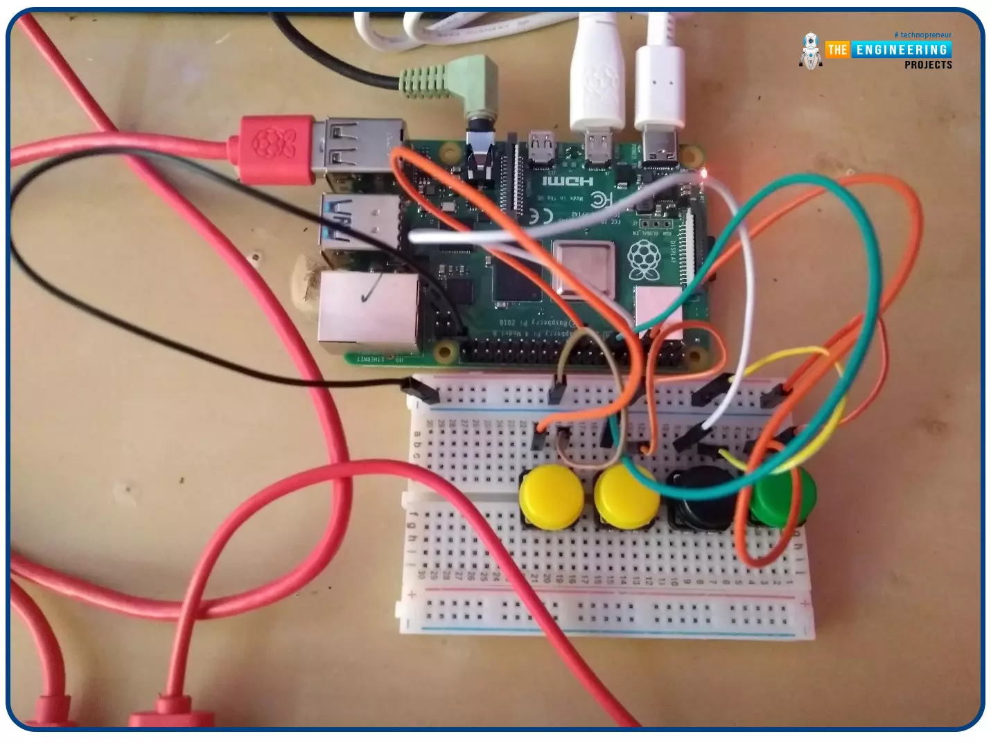
Welcome to the next tutorial of our Raspberry Pi programming course. Our previous tutorial taught us to make a button-controlled "music box" that plays different sounds depending on which buttons are pressed. In this lesson, we will configure our raspberry pi for voice control.
What will you learn?
Like the Amazon Echo, voice-activated gadgets are becoming increasingly popular, but you can also construct your own with a Raspberry, a cheap USB mic, and some appropriate software. Simply speaking to your Raspberry Pi will allow you to search YouTube, view websites, activate applications, and even answer inquiries.
What will you need?
Because the Raspberry Pi lacks a soundcard or audio port, this project requires a USB microphone or a camera with a ...
Welcome to the next tutorial of our Raspberry Pi programming course. In our previous tutorial, we learned how to create a timelapse video with still images and understand how phototimer and FFmpeg work. In this lesson, you'll make a button-controlled "music box" that plays different sounds depending on which buttons are pressed.
What you will learn
Connect button pushes to function calls using the Python gpiozero package and uses the Python dictionary data structure
Components
Raspberry Pi
Breadboard
Buttons
Jumper wires
Speaker
Set up your project
For this project, you'll need some audio samples. On Raspbian, there are many audio files; however, playing them with Python can be challenging. You can, however, transform the audio files ...
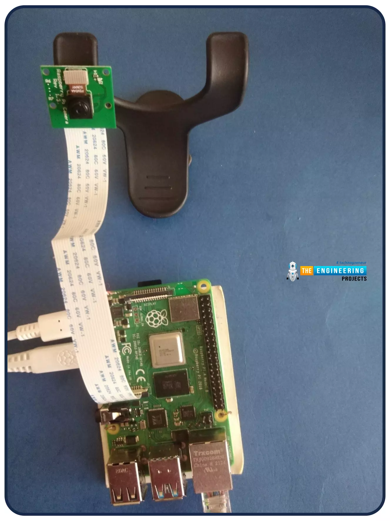
Welcome to the next tutorial of our Raspberry Pi programming course. Our previous tutorial looked at how to Interface DS18B20 with Raspberry Pi 4. This tutorial will teach us how to create a time-lapse video with still images and understand how phototimer and FFmpeg work.
What is time-lapse?
When photographing something over a lengthy period, "time-lapse" comes to mind. A video can be created by mixing the still photos. Plant development may be tracked with time-lapse movies, as can the changing of the seasons. They can also be utilized as low-resolution security cameras.
Components
Raspberry pi 4B
Pi camera
Connect to the Raspberry Pi
Cameras that can be used with the Raspberry Pi are a bit limi ...
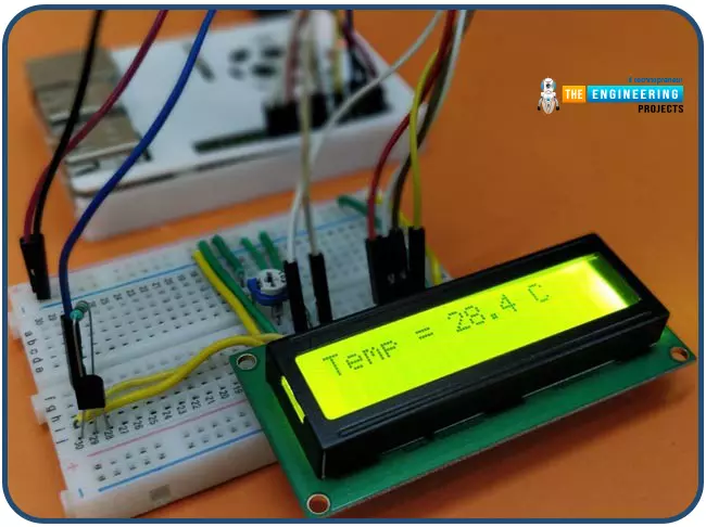
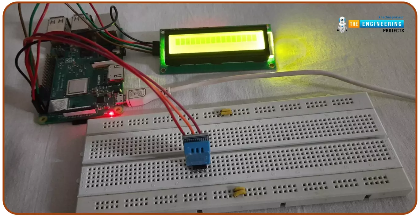
Hello friends, I hope you all are having fun. Today, we are going to share the 7th tutorial of Section-III in our Raspberry Pi Programming Course. In the last tutorial, we interfaced a DHT11 sensor with Raspberry Pi 4. Today, we are going to interface another temperature sensor i.e. DS18B20 with Raspberry Pi 4.
DS18B20 is a popular temperature sensor especially in severe/critical environments i.e. chemical plants, mines, industrial sites etc. because of its 1-wire operational technique and accurate readings up to 4 decimal digits.
Project Description
Today, we will interface a DS18B20 temperature sensor with Raspberry Pi 4 and will display the values on a 16x2 LCD.Let's have a look at the components required for this project:
Components ...
Hello friends, I hope you all are doing great. Today, I am going to share the 6th tutorial of Section-III in the Raspberry Pi Programming Course. In our previous tutorial, we have seen how to interface an Ultrasonic Sensor with Raspberry Pi 4 and used Python to perform its calculations. In today's tutorial, we'll discuss how to interface a DHT11 temperature and humidity sensor to a Raspberry Pi. So, let's get started:
ComponentsHere's the list of components, we are going to use in today's circuit:
LCD display
DHT11 sensor
Raspberry pi
Breadboard
Male-to-female jumper wires
What is a DHT11 sensor?
DHT11 is a low-cost digital sensor, used to measure temperature and humidity in the surr ...
Hello friends, I hope you all are doing well. Today, I am going to share the 5th tutorial of Section-III in our Raspberry Pi Programming Course. In our previous tutorial, we have seen the interfacing of a PIR Sensor with Raspberry Pi 4. In today's tutorial, we will interface an Ultrasonic sensor with Raspberry Pi and will use Python to perform its calculations. So, let's get started:
Components:Here's the list of components, we are going to use in today's project:
Raspberry Pi 4
Ultrasonic sensor
Male-to-female jumper wires
Breadboard1k ohm resistor
2k ohm resistor
What are Ultrasonic Sensors?
An Ultrasonic Sensor consists of a transmitter and a receiver, the transmitter emits the ultrasonic wave, which after hitting some ob ...
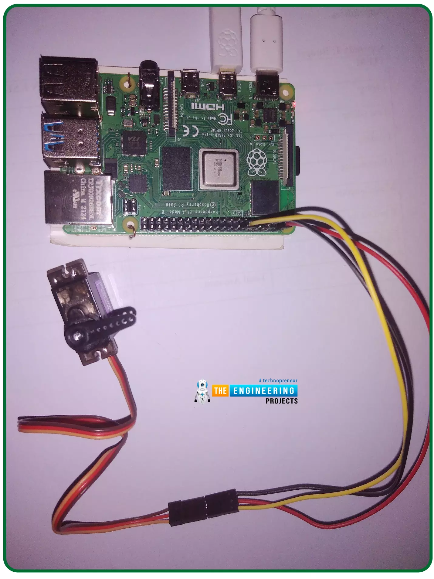
Hello friends, I hope you all are doing well. Welcome to the 11th tutorial of our Raspberry Pi programming course. In the previous chapter, we have seen how to regulate the speed of a Stepper motor with Raspberry Pi 4. Today, we'll work on the servo motor and will control it with RPi4. So, let's get started:
Components Required:We will need the following components to control Servo Motor with Raspberry Pi 4:
Raspberry Pi 4.
Servo Motor.
Male-to-female jumper wires.
What is a servo motor?
A Servo Motor is a simple DC motor with a position feedback Control System and a gearbox.A Servo Motor's primary advantage is its ability to maintain its shaft's angular position at any desired angle i.e. if we want to keep our shaft at 67 degre ...
Hello friends, I hope you all are having fun. Welcome to the 10th tutorial of our Raspberry Pi programming course. In the last chapter,
PWM was utilized to regulate the DC motor's speed and direction
with a motor driver L293D. In this chapter, we'll advance our skills with PWM and use it to control a stepper motor using the same motor driver L293D.Here's the video demonstration of this project:Let's get started:
Components RequiredHere's the list of components, which we will use to control the speed and direction of Raspberry Pi 4:
Raspberry Pi 4.Stepper Motor.
Motor Driver IC(L293D).
Jumper wires.
9V Battery.
Breadboard.
The Raspberry Pi with desktop is required for this project. An SSH connection can be made, or the RPi can ...