Introduction to PC817
- PC817 is a 4 Pin optocoupler, consists of an Infrared Emitting Diode (IRED) & photo transistor, which enables it optically connected but electrically insulated.
- Inrared Emitting Diode is connected to first two Pins and if we apply power to it, then IR waves are emitted from this diode, which makes the photo transistor forward biased.
- If there's no power on the input side, diode will stop emitting IR waves and thus photo transistor will reverse biased.
- PC817 is normally used in embedded project for isolation purposes.
- In my embedded projects, I place PC817 after Microcontroller Pins to isolate back EMF, in case of motor control etc.
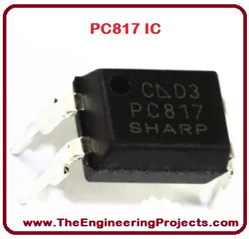
- PC-817 has several applications e.g. noise suppression in switching circuits, input/output isolation for MCU (Micro Controller Unit). PC 817 is shown in the figure given below.
- You can download PC817 Datasheet by clicking below button:
| PC817 Features | |||
|---|---|---|---|
| No. | Parameter | Value | |
| 1 | Pin Count | 4 | |
| 2 | Manufacturer | Sharp | |
| 3 | IRED | 1 | |
| 4 | Forward Current | 50mA | |
| 5 | Peak Forward Current | 1A | |
| 6 | Reverse Voltage | 6V | |
| 7 | Power Dissipation | 70mW | |
| 8 | Collector Emitter Voltage | 80V | |
| 9 | Emitter Collector Voltage | 6V | |
| 10 | Collector Current | 50mW | |
| 11 | Collector Power Dissipation | 150mW | |
| 12 | Total Power Dissipation | 200mW | |
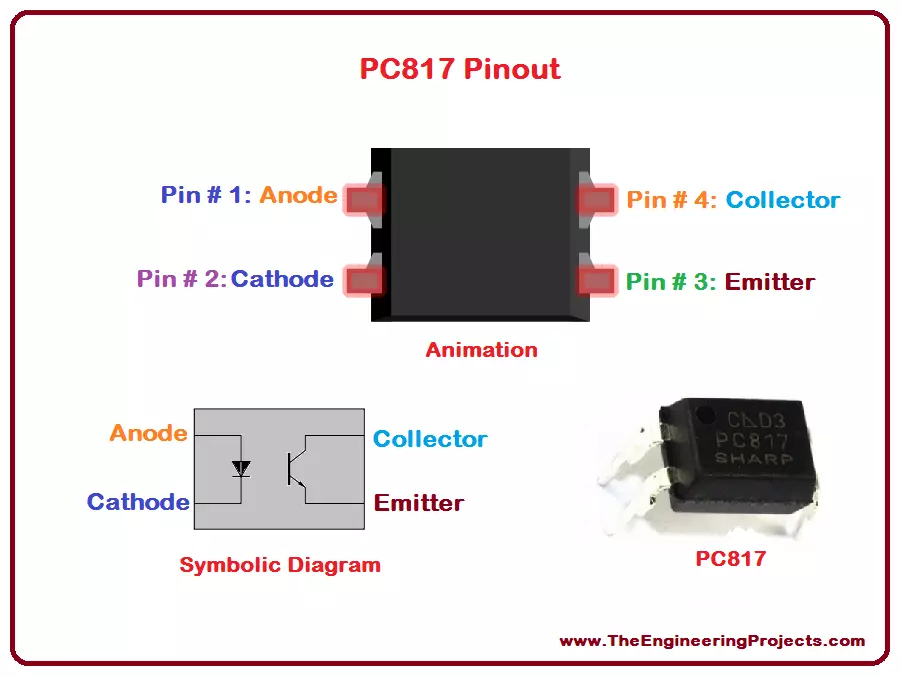
1. PC817 Pinout
- PC817 Pinout consists of four (4) pins in total, first two are connected with the Infrared Emitting Diode (IRED) while the last two are connected with Photo Transistor.
- All of these four pins are given in the table shown below, along with their name & status.
| PC817 Pinout | |||
|---|---|---|---|
| Pin No. | Pin Name | Status | |
| Pin # 1 | Anode | Input | |
| Pin # 2 | Cathode | Input | |
| Pin # 3 | Emitter | Output | |
| Pin # 4 | Collector | Output | |
- PC817 Pinout diagram is shown in the figure below:
2. PC817 Packages
- Different packages of the same device presents its models with some modifications or extra features.
- PC 817 has four packages, displayed in below table:
| PC817 Packages | ||
|---|---|---|
| No. | Package Type | Example |
| 1 | Through-Hole | PC817X |
| 2 | SMT Gullwing Lead-Form | PC817XI |
| 3 | Wide Through-Hole Lead-Form | PC817XF |
| 4 | Wide SMT Gullwing Lead-Form | PC817XFP |
3. PC817 Symbolic Representation
- Symbolic diagram presents internal structure and functionality of any device.
- PC 817 symbolic representation is given in the figure shown below:

4. PC817 Features
- The features of anything shows its ability to do something different and unique as compared to the others.
- All of the amazing features associated in the PC-817 are shown in the table given below.

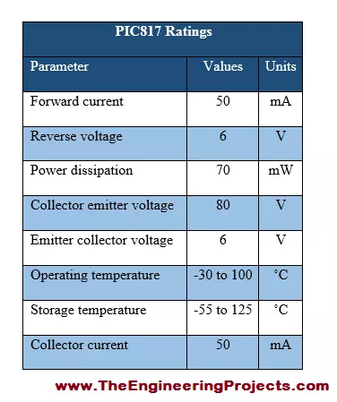
5. PC817 Ratings
- Ratings of an equipment shows shows basically the operating conditions of that particular device,and they may vary from device to device.
- The power, current and voltage ratings of PC 817 are given in the table shown below.
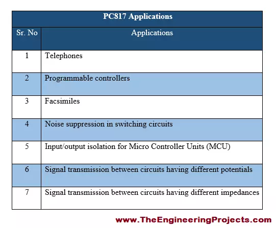
7. PC817 Applications
- Any electronic device is usually known on the basics of its real life applications.
- Real life applications are highly related to the popularity of a device.
- some of the major real life applications of PC-817 are provided in the table shown below.